Mandik SEDS-R User manual


1
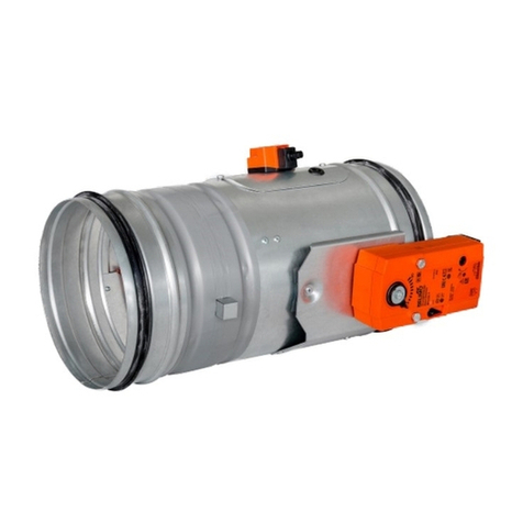
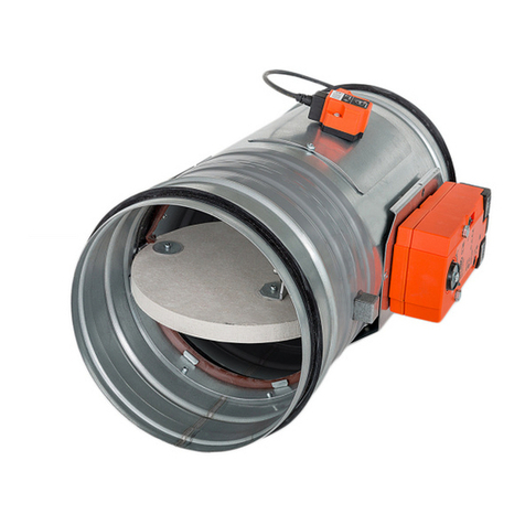
These technical specifications state a row of manufactured sizes and models of round smoke extraction dampers - single
(further only dampers) SEDS-R. It is valid for production, designing, ordering, delivery, maintenance and operation.
1. Description.........................................................................................................................
2
2. Design................................................................................................................................
3
3. Dimensions, weights...........................................................................................................
7
4. Placement and Assembly....................................................................................................
8
5. Pressure loss......................................................................................................................
10
6. Coefficient of local pressure loss.........................................................................................
10
7. Noise data and pressure loses...........................................................................................
11
8. Material...............................................................................................................................
12
9. Inspection, testing..............................................................................................................
12
10. Logistic terms....................................................................................................................
12
11. Assembly..........................................................................................................................
12
12. Entry into service and revisions.........................................................................................
13
13. Spare parts.......................................................................................................................
13
14. Product label.....................................................................................................................
14
15. Ordering key.................................................................................................................….
14

2
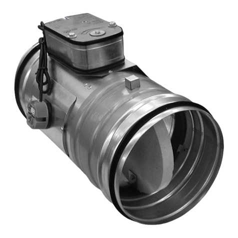
Smoke extraction dampers - single are shutters in smoke exhaust piping systems. Dampers are
designed to remove heat and combustion products (e.g. smoke) from single fire compartment.
In the event of fire the Smoke and Fire ventilation system opens the damper in the affected
section which removes combustion products and heat from this section.
The damper blade is operated by an actuating mechanism.
The dampers can be installed in various duct sizes with respect to the field of direct applications
according with EN 1366-9.
The field of direct applications based on tests results is acceptable according to EN 1363-1,
part A.1 and A.2, EN 1366-2, part 13 and EN 1366-10, part 9.
Round smoke extraction dampers only for duct installation - single are classified as
The duct can be ended by KMM (TPM 002/96) grilles. During grilles installation blade overlaps
has to be respected see chapter 3.3.
Damper characteristics
• CE certified acc. to EN 12101-8
• Tested in accordance with EN 1366-10
• Classified acc. to EN 13501- 4+A1
• External Casing leakage min. class B, Over blade min. class 4, diameter 100 min. class 3
• Cycling test in class C 10000 acc. to EN 12101-8
• ES Certificate No. 1391-CPR-2016/0143
• Declaration of Perfomance No. PM/SEDS-R/01/20/1
• Hygienic assessment of fire dampers - Report No. 1.6/pos/19/19c

3
Working conditions
Dampers are designed for smoke exhaust piping systems with underpressure max. 1500 Pa or
overpressure max. 500 Pa.
Dampers are designed for maximum air velocity 15 m.s .
Dampers are designed for installation with horizontal blade axis. Flow direction has to be led from
actuating side (it is labeled by arrow on the damper casing).
Dampers are suitable for systems without abrasive, chemical and adhesive particles.
Dampers are designed for macroclimatic areas with mild climate according to EN 60 72133.
Temperature in the place of installation is permitted to range from - 30°C to + 50°C.
Design with actuating mechanism
SEDS-R is equipped by actuating mechanism Belimo BLE24 for 24V supply or BLE230 for 230V
supply. After being connected to power supply the actuating mechanism displaces the damper
blade into operation position "OPEN" or „CLOSED“ (according to method of connection, see
connection diagram). Running time is max. 60s. If is power supply cut off, actuating mechanism
is stopped in actual position. The crank handle supplied with the actuator allows it to be operated
manually. Signaling of the damper blade positions "OPEN" and "CLOSED" is provided by means
of two integrated, invariably set terminal switches.
~
+-
S2S1 S3 S5S4 S6
BLE24-ST: Design with connector plugs for communication
Connection through
an insulation transformer.
to network and communication device BKNE230-24
Parrallel connection of other driver is possible.
Pay attention to the power input data.
2
13
<3° <87°

4
Design with the communication and power supply unit
Design with the communication and power supply unit BKNE230-24 and the actuating mechanism
BLE24(BE24-12)-ST.
BKNE230-24 functions as a decentralized network device for supplying the actuating mechanism
BLE24(BE24-12)-ST on one hand and on the other hand it transmits signals from communication
and control device BKSE24-6.
It simplifies electrical wiring and interconnection of dampers. It facilitates on site check and
enables central control and checks of fire damper by means of a simple 2-conductor wiring.
BKNE230-24 signals the damper position „OPEN“/„CLOSED“ (from switches on the actuator)
and any fault alarms to the BKSE24-6 unit. It also receives positioning commands from the
control unit and triggers the actuator to the required position. The last control command is
retained troughout temporary power failures.
The BKNE230-24 unit monitors the positions of the switches on the actuator, its running time and
the exchange of data with the control and monitoring unit BKSE24-6. It also monitors the actuator
current and the power supply. In order to make installation as simple as possible the smoke
extraction damper actuators ...-ST are fitted with plug connectors that can be inserted directly into
the BKNE230-24 unit.
The 2-wire conductor must be connected to screw terminals 6 and 7. It is recommended that a
fire alarm signal cable suitable for the application be used for the 2-wire conductor. It is essential
to ensure the correct polarity.
More information in catalogue Belimo.
2
1
N
S3S2
S1 S6S5S4
<3° <87°
Parrallel connection of other driver is possible.
Pay attention to the power input data.
3
L1
Nominal voltage AC 24V 50/60Hz
DC 24 V
AC 230 V 50/60Hz
Power consumption - motoring
- holding
7,5 W
< 0,5 W
5W
< 1 W
Dimensioning 9 VA (Imax 2,7 A @ 5 ms) 12 VA (Imax 6 A @ 5 ms)
Protection class III II
Degree of protection IP 54
Running time for 95° < 30 s
Ambient temperature range
Non-operating temperature
- 30 °C … + 50 °C
- 40 °C … + 80 °C
Connecting - motor
- auxiliary switch
cable 1 m, 3 x 0,75 mm
cable 1 m, 6 x 0,75 mm
(BLE 24-ST) with plug-in connectors

5

6
Communication and control devices
Nominal voltage AC 230V 50/60Hz
Power consumption 10 W (including actuating mechanism)
Dimensioning 19 VA (including actuating mechanism)
Degree of protection II
Ambient temperature range
Non-operating temperature
- 30 °C … + 50 °C
- 40 °C … + 80 °C
Connecting - net
- actuator
- terminal board
cable 1 m without plug
6-pole connector, 3-pole connector
screw terminals for cable 2x1,5 mm
BKSE24-6 indicates operating status and fault signals for the smoke extraction dampers. The
auxiliary contacts that are incorporated also allow functions to be signaled or passed on to
higherlevel control systems. The signals from the BKNE230-24 unit are received by the
BKSE24-6 unit and evaluated individually. All BKNE230-24 units are triggered simultaneously.
To BKSE24-6 can be connected max. 6 BKNE230-24.
Communication is via the 2-wire conductor. Correct operation of the dampers is indicated by
means of two LEDs. The operating status of the SBSE-Control system and any faults are also
indicated by this LED and the corresponding fault LED.
The BKSE24-6 unit can be clipped directly to a 35 mm DIN mounting rail and connected by
means of two 9-pole plug-in terminals.
17
an insulation transformer.
~
AC 24 V
18
SMOKE EXTRACTION
Connection through
15
16
13
14
2
1
4
3
6
5
7
9
8
11
12
10
+
-
U
a1...a6
a1...a6
BKNE230-24
Input 2
(isolated)
AUTO
CEASE SMOKE EXTRACTION
COM
Delay 0 s (Fan)
Delay 60 s (Fan)
OPEN
CLOSED
*Fault (Error)
*Inverted output: fault = contact open
Input 1
Nominal voltage AC 24 V 50/60Hz
Power consumption 3,5 W (operating position)
Dimensioning 5,5 VA 18 VA (Imax 6.4 A @ 2.5 ms)
Protection class III
Degree of protection IP 20
Ambient temperature range 0 … + 50 °C
Connecting screw terminals for cable 2x1,5 mm

7
Dimensions
1 Damper body
2 Damper blade
3 Actuating mechanism cover
4 Installation flange
Weights and effective area
- - 10 0,0061 BELIMO BLE (15 N.m)
- - 10,5 0,0100 BELIMO BLE (15 N.m)
- - 11 0,0172 BELIMO BLE (15 N.m)
- - 11,5 0,0222 BELIMO BLE (15 N.m)
- - 12 0,0278 BELIMO BLE (15 N.m)
- - 13 0,0446 BELIMO BLE (15 N.m)
- - 13,5 0,0565 BELIMO BLE (15 N.m)
15,5 - 14,5 0,0722 BELIMO BLE (15 N.m)
35,5 - 15,5 0,0925 BELIMO BLE (15 N.m)
58 18 16,5 0,1183 BELIMO BLE (15 N.m)
83 43 18 0,1508 BELIMO BLE (15 N.m)
108 68 19,5 0,1872 BELIMO BLE (15 N.m)
138 98 21,5 0,2360 BELIMO BLE (15 N.m)
173 133 24,5 0,3001 BELIMO BLE (15 N.m)

8
Smoke extraction dampers single are designed to remove heat and combustion products (e.g.
smoke) from single fire compartment according EN1366-9.
Smoke extraction dampers single are designed for installation with horizontal blade axis.
Backtoback smoke exhaust duct has to be hung or supported so as all load transfer from the
backtoback smoke exhaust duct to the damper is absolutely excluded. To provide needed
access space to the control device, all other objects must be situated at least 350 mm from the
control parts of the damper.
During installation the damper blade must be in position CLOSED. The damper body should
not be deformed in the course of installation. Once the damper built in, its blade should not grind
on the damper body during opening or closing.
For damper (Fig. 9) the open damper blade overlaps the damper body from dimension D = 315
by the value “a” or “a” and “c”. These values are specified in the Tab. 3.2.1.
Values "a" and "c" has to be respected when projecting related smoke exhaust ducts.

9
Installation examples
Position:
1
Damper hinge
2 Holder L
3
Threaded rod
4
Washer
5
Nut
6
Screw connection
7
Profile 30x30

10
Pressure loss calculation
p
=
w2
2
p [Pa] presure loss
w [m.s ] air flow speed in nominal damper section
[kg.m ] air density
[-] coefficient of local pressure loss for the nominal damper section
(see Tab. 6.1.1.)
Determination of pressure loss by using diagram = 1,2 kg.m
Coefficient of local pressure loss (-)
1,111 0,930 0,760 0,649 0,576 0,500 0,424
0,381 0,341 0,315 0,283 0,252 0,214 0,182

11
85 113 141 170 198 226 254 283 842
1122
1403
1683
1964
2244
2525
2806
19 26 32 37 41 45 48 50 6 13 19 24 28 31 34 37
6 11 17 24 33 43 54 67 2 4 6 8 11 15 19 23
133 177 221 265 309 353 398 442
1069
1425
1782
2138
2494
2851
3207
3563
20 27 33 38 42 45 48 51 6 13 19 24 28 32 35 37
5 9 14 20 27 36 45 56 2 3 5 7 10 13 17 20
217 290 362 434 507 579 651 724
1357
1810
2262
2714
3167
3619
4072
4524
18 25 31 36 40 43 46 49 6 14 20 24 28 32 35 38
4 7 11 16 22 29 37 46 2 3 5 7 9 12 15 19
275 366 458 550 641 733 824 916
1716
2289
2861
3434
4006
4578
5150
5722
17 24 30 35 39 42 46 48 5 13 19 23 27 31 34 37
4 6 10 14 19 25 32 39 2 3 4 6 8 11 14 17
339 452 565 679 792 905
1018
1131
2121
2827
3534
4241
4948
5655
6362
7069
16 23 29 34 38 41 44 47 4 12 18 22 26 30 33 36
3 6 9 12 17 22 28 35 1 2 4 5 7 10 12 15
530 707 884
1060
1237
1414
1590
1767
2659
3545
4431
5317
6203
7090
7976
8862
12 20 26 30 34 38 41 44 3 11 17 21 25 29 32 35
3 5 7 11 15 19 24 30 1 2 3 5 6 8 10 13
665 886
1108
1329
1551
1773
1994
2216
3367
4489
5611
6733
7855
8978
10100
11222
8 17 22 29 32 35 36 39 2 10 16 20 24 28 31 34
2 4 6 9 12 16 21 25 1 2 3 4 5 7 9 11

12
Damper casing and damper blade are made of galvanized plate without any other surface finish.
Fasteners are galvanized.
The appliance is constructed and preset by the manufacturer, its operation is dependent on
proper installation and adjustment.
Dampers are transported by box freight vehicles without direct weather impact, there must not
occur any shocks and ambient temperature must not exceed + 40 °C. Dampers must be protected
against mechanic damages when transported and manipulated. During transportation, the
damper blade must be in the "CLOSED" position.
Dampers are stored indoor in environment without any aggressive vapours, gases or dust. Indoor
temperature must be in the range from -30 °C to +40 °C and maximum relative humidity 95 %
(avoid condensation on the damper body). Dampers must be protected against mechanic
damages when transported and manipulated.
To ensure reliable smoke exhaust damper function it is necessary to avoid blocking the closing
mechanism and contact surfaces with collected dust, fibre and sticky materials and solvents.
Without power supply, the damper can be operated manually and fixed in any required position.
All effective safety standards and directives must be observed during damper assembly.
Assembly, maintenance and damper function check can be done only by qualified and trained
person, i.e. “AUTHORIZED PERSON” according to the manufacturer documentation. All works
done on the fire dampers must be done according international and local norms and laws.

13
Check of damper blade displacement can be realize after actuating mechanism supply connec-
tion or signal connection from higher level control systems. Blade displacement from position
“OPEN” to position “CLOSED” and return displacement is checked.
Spare parts are supplied only on basis of an order.
Before entering the dampers into operation after assembly and after sequential revisions, checks
and functionality tests of all designs including operation of the electrical components must be
successfully provided and finished. After entering into operation, these revisions must be done
according to requirement set by national regulations.
In case that dampers are found unable to serve for their function for any cause, it must be clearly
marked. The operator is obliged to ensure that the damper is put into condition in which it is ready
for function and meanwhile he is obliged to provide the fire protection by another appropriate way.
Results of regular checks, imperfections found and all-important facts connected with the damper
function must be recorded in the "FIRE BOOK" and immediately reported to the operator.
Before entering the dampers into operation after their assembly and by sequential checks, the
following checks must be carried out for all designs.
Visual inspection of proper damper integration, inside damper area, damper blade, contact
surfaces and silicon sealing.
For electrical connection of the actuator use the prefabricated slot in the protection box on the top
side of the box.
2x Ø10mm
If it is necessary to use other position of the connecting holes, then make two holes to the
protection box to pull in connecting cables (heat resistant cables) to the cables of damper´s
actuator. Protection box is made of calcium silicate plates.
●use drill Ø10 and make two holes (see figure 11). It is possible to make 2 holes in any wall
of the box.
●pull the heat resistant cable through the calcium silicate plate (wall) and connect with cables
from actuator according to above mentioned electrical diagram
●seal up the space in the hall with fire resistant mastic or sealant
●let the sealant harden

14
technical specifications
design according chapter 2.1 and 2.2
size
type
Product label is placed on the damper casing
WEIGHT (kg):
Dobříšská 550, 267 24 Hostomice, Czech Republic
MANDÍK, a.s.
ACTUATING SYSTEM:
YEAR/SER.NO.:
DIMENSION:
1391
EN 12101-8:2011
TPM 120/16
R
FIRE PROTEC. CLASS:
MANUAL
Cert. No.: 1391-CPR-2016/0143, DoP: PM/SEDS-R/01/20/1

The producer reserves the right for innovations of the product. For actual product information see
www.mandik.com
MANDÍK, a.s.
Dobříšská 550
26724 Hostomice
Czech Republic
Tel.: +420 311 706 706
E-Mail: [email protected]
www.mandik.com
Other manuals for SEDS-R
1
Table of contents
Other Mandik Fire And Smoke Damper manuals
Popular Fire And Smoke Damper manuals by other brands

Bredel
Bredel Pulsation damper Series manual

Exhausto
Exhausto VEX40T Assembly instruction

Greenheck
Greenheck FSD Series Installation, operation and maintenance instructions

Zonefirst
Zonefirst ZDS Installation instruction

STABILUS
STABILUS Ace FRT-E2-100 Operating and mounting instructions

KOOLAIR
KOOLAIR SF Series manual