True blue power TA360 Series Technical Document

Installation Manual and Operating Instructions
TA360 Series
USB Power Delivery Charging Port
True Blue Power® is a division of Mid-Continent Instrument Co., Inc.
Mid-Continent Instrument Co., Inc.
dba Mid-Continent Instruments and Avionics
9400 E. 34th Street N.
Wichita, KS 67226 Manual number 9019411
PH (800) 821-1212 FX (316) 630-0723 Revision A, October 18, 2019

Rev A, October 18, 2019 2 Manual Number 9019411
FOREWORD
This manual provides information intended for use by persons who, in accordance with current
regulatory requirements, are qualified to install this equipment. If further information is required,
please contact:
True Blue Power
c/o Mid-Continent Instrument Co., Inc.
Attn: Customer Service Dept.
9400 E. 34th Street N.
Wichita, KS 67226 USA
PH (316) 630-0101
FX (316) 630-0723
www.truebluepowerusa.com
www.mcico.com
We welcome your comments concerning this manual. Although every effort has been made to
keep it free of errors, some may occur. When reporting a specific problem, please describe it
briefly and include the manual part number, the paragraph/figure/table reference and the page
number. Send your comments to:
True Blue Power
c/o Mid-Continent Instrument Co., Inc.
Attn: Technical Publications
9400 E. 34th Street N.
Wichita, KS 67226 USA
PH (316) 630-0101
FX (316) 630-0723
All products produced by Mid-Continent Instrument, Co., Inc., including those identified as Mid-
Continent Instruments and Avionics or True Blue Power, are designed and manufactured in
Wichita, KS, USA.
© Copyright 2019
Mid-Continent Instrument Co., Inc.

Rev A, October 18, 2019 3 Manual Number 9019411
REVISION HISTORY
Rev. Date Approved Detail
A 10/18/19 BAW Initial release.

Rev A, October 18, 2019 4 Manual Number 9019411
TABLE OF CONTENTS
SECTION 1 GENERAL DESCRIPTION
1.1 INTRODUCTION
1.2 TECHNICAL SPECIFICATIONS
1.2.1 ELECTRICAL ATTRIBUTES
1.2.2 PHYSICAL ATTRIBUTES
1.2.3 QUALIFICATIONS
1.2.4 VERSIONS
SECTION 2 PRE-INSTALLATION CONSIDERATIONS
2.1 COOLING
2.2 EQUIPMENT LOCATION
2.3 ROUTING OF CABLES
2.4 LIMITATIONS
2.5 MODIFICATIONS
SECTION 3 INSTALLATION PROCEDURES
3.1 GENERAL INFORMATION
3.2 UNPACKING AND INSPECTING
3.3 CABLE HARNESS
3.3.1 WIRE GAUGE SELECTION
3.3.2 PIN ASSIGNMENT INFORMATION
3.3.3 HARNESS VERIFICATION
3.4 MOUNTING
3.5 INSTALLATION COMPLETION
SECTION 4 OPERATION
4.1 ELECTRICAL PERFORMANCE
4.2 PROTECTIVE FEATURES
4.2.1 OVER-CURRENT PROTECTION
4.2.2 SHORT CIRCUIT PROTECTION
4.2.3 LOW INPUT VOLTAGE SHUTDOWN
4.2.4 OVER-TEMPERATURE
4.2.5 REVERSE POLARITY
SECTION 5 CONFORMANCE
5.1 CONTINUED AIRWORTHINESS STATEMENT
5.2 ENVIRONMENTAL QUALIFICATION STATEMENT

Rev A, October 18, 2019 5 Manual Number 9019411
SECTION 1 GENERAL DESCRIPTION
1.1 INTRODUCTION
The TA360 Series USB Power Delivery (PD) Charging Port is a certified accessory that charges any
electronic device that uses either a USB Type-A or USB Type-C charging connector.
The TA360 supports the latest version of the USB charging standard, known as USB Power Delivery (PD)
version 2.0 and 3.0. This smart charger provides intelligent negotiation with the connected cable and
device to supply variable voltage at up to 3 amps, allowing up to a total of 60 watts of charging power.
This provides maximum charging speed to a wide variety of the latest electronic devices, including mobile
phones, tablets - even laptops - and more. By determining the maximum power the device can support,
the TA360 will always charge the device at the maximum speed allowed, while preventing the device from
being overcharged or charged incorrectly. The TA360 also incorporates True Blue Power’s proprietary
Cable-Drop Compensator which cancels the effect of voltage lost through the cable, extending the
flexibility of cable/device combinations while maintaining the fastest charging possible.
The TA360 accepts an input of 22-32 volts DC from the aircraft and converts it to an output voltage from 5
to 20 volts DC, at a current up to 3 amps per port. The TA360 incorporates the latest USB Type-C
connector to supply PD power, offering a smaller and reversible port connection, in either a single or dual
port configuration. Additionally, a version is available that includes both a traditional USB Type-A port
combined with a USB PD Type-C port to support both legacy and newer cables and devices. Each
version is available with or without lighting to conveniently locate the charging ports in low-light
conditions. The unit has built-in protections for short circuit, over-current, and low voltage conditions. It is
designed to protect against reverse polarity installation and has temperature monitoring and shutdown
capability, allowing the unit to handle unforeseen conditions safely.
The TA360 is certified to FAA/TSO-C71 and qualified to multiple RTCA DO-160G environmental
conditions for ease of installation and incorporation on any class or type of aircraft. The unit is easily
mounted with two screws and a two-wire power input and can be installed throughout the aircraft,
including the cockpit, cabin, galley, or other locations.
Small, compact and powerful, with plenty of installation flexibility, the TA360 is an ideal choice in any
aircraft to charge the latest electronic devices at maximum speed.

Rev A, October 18, 2019 6 Manual Number 9019411
1.2 TECHNICAL SPECIFICATIONS
1.2.1 Electrical Attributes
Input Voltage 22-32 VDC
Input Power 135 watts max; 4.8 amps @ 28 VDC
Output Voltage Auto-adjustable: 5VDC, 9VDC, 15VDC, 20VDC per port
(±0.25 VDC)
Output Power 3.0 amps max per port
Efficiency ~90% nominal
Table 1.1
1.2.2 Physical Attributes
Weight 1.0 ox (28 g) (single Type-C port)
1.8 oz (51 g) (dual Tpe-A/Type-C port)
2.1 oz (60) (dual Type-C port)
Dimensions (Single Port Units)
(not including mating connector)
1.50 inches wide X 0.52 inches high X 2.0 inches deep
(38mm wide X 13mm high X 50mm deep)
Dimensions (Dual Port Units)
(not including mating connector)
1.50 inches wide X 1.03 inches high X 2.0 inches deep
(38mm wide X 26mm high X 50mm deep)
Charging Port Connector USB Type-A or USB Type-C
Input Connector Kit MCIA P/N 9017960
Mounting Panel mount; rear
Table 1.2
1.2.3 Qualifications
Certification: FAA/TSO-C71
Environmental Qualification: RTCA/DO-160G (See Section 5 for Categories/Levels)
USB Power Delivery (PD) Version 2.0 and Version 3.0
USB Battery Charging (BC) Version 1.2
Table 1.3
1.2.4 Versions
Non-Lighted Lighted USB Connector
Part
Numbers
6430360-1 6430360-11 Dual: Type A +Type C
6430360-3 6430360-13 Dual: Type C +Type C
6430360-7 6430360-17 Single: Type C
Table 1.4

Rev A, October 18, 2019 7 Manual Number 9019411
SECTION 2 PRE-INSTALLATION CONSIDERATIONS
2.1 COOLING
No external cooling is required. The unit will become warm when in use. This is normal and within
operational parameters. No special mounting considerations are required; however, mounting to a metal
surface can help dissipate any heat generated and extend the life of the product.
2.2 EQUIPMENT LOCATION
The TA360 High Power USB Charging Port is designed for mounting flexibility, allowing for installation in
the cockpit or in the cabin. It is designed for panel mounting and can be installed in a rectangular
configuration or, with an available installation kit, can be front mounted with a cosmetic cover plate. An
instrument mounting adapter bracket is also available to easily mount the unit in a standard 2-inch round
instrument opening that may already exist in the cockpit panel. There are two versions to choose from
which allow the input connector to be located either on the rear of the unit or from the bottom.
The unit can be mounted in any orientation. Clearance should be provided for the mating connector which
may require up to an additional inch beyond the rear of the unit.
2.3 ROUTING OF CABLES
Avoid sharp bends in cabling and routing near aircraft control cables. Avoid close proximity and contact
with aircraft structures, avionics equipment or other obstructions that could chafe wires during flight and
cause undesirable effects.
2.4 LIMITATIONS
Environmental qualifications were verified per RTCA DO-160, Revision G in lieu of those identified within
the minimum performance standards (MPS) of the TSO.
The conditions and tests for TSO approval of this article are minimum performance standards. Those
installing this article, on or in a specific type or class of aircraft, must determine that the aircraft installation
conditions are within the TSO standards, specification of the article and deviations as listed above. TSO
articles must have separate approval for installation in an aircraft. The article may be installed only
according to 14 CFR part 43 or the applicable airworthiness requirements.
The USB PD is an extremely capable new technology for personal electronic devices. Beyond the
physical format of the Type-C connector, it also allows for a variety of interface options when
communicating with compatible devices. This device-to-charger communication is defined within the USB
3.1 Specification and Power Delivery standards. However, manufacturers of consumer electronic devices
and/or cables may choose to implement proprietary versions or modifications of the USB standards to
operate specifically with their own charging equipment. The TA360 has been tested with and supports a
wide variety of devices now emerging on the open market. However, compatibility with all devices may
not be guaranteed. True Blue Power continues to be proactive in evaluating new devices and strives to
continually improve the product as needed to serve the vast majority of USB-charged electronic products.

Rev A, October 18, 2019 8 Manual Number 9019411
2.5 MODIFICATIONS
Each TA360 USB Power Delivery Charging Port (part number 6430360-( )) has a nameplate that
identifies the manufacturer, model, part number, description, certifications and technical specifications of
the unit. The nameplate also includes the “MOD” or modification status representing notable changes in
the design of the unit. The following identifies each “MOD” or modification.
Modification (MOD) 0 is the initial release of the TA360 USB Power Delivery Charging Port and is
identified on the nameplate by the lack of marking on the MOD numbers 1 through 9 (i.e. 1-9 are visible).
All subsequent modifications are identified on the nameplate by the marking/blacking out of that particular
MOD number (i.e. for MOD 1, the number 1 is not visible and 2-9 are visible). See Figure 2.1 for examples.
For additional details regarding design changes to the TA360 USB Power Delivery Charging Port, refer to
individual Service Bulletins associated with each MOD.
MOD 0 MOD 1
Figure 2.1
Nameplate and MOD Status Examples

Rev A, October 18, 2019 9 Manual Number 9019411
SECTION 3 INSTALLATION PROCEDURES
3.1 GENERAL INFORMATION
This section contains interconnect diagrams, mounting dimensions and other information pertaining to the
installation of the TA360 Single and Dual USB Charger. After installation of cabling and before installation
of the equipment, ensure that power and ground are applied to the proper pins specified in Section 3.3.2,
Pin Assignment Information.
3.2 UNPACKING AND INSPECTING EQUIPMENT
When unpacking this equipment, make a visual inspection for evidence of any damage that may have
occurred during shipment. The following parts should be included:
a. High Power USB Charging Port MCIA P/N 6430360-( )
b. Installation Manual MCIA P/N 9019411
c. Connector Kit MCIA P/N 9017960
i. Mating Connector, 2-pin
ii. Pins (4) (2 required, 2 spares)
iii. Screws, #4-40 x 1/4 flat-head (2)
iv. Screws, #4-40 x 5/16 flat-head (2)
Optional Equipment Available:
a. Instrument Mount Adapter Kit MCIA P/N 9017947
b. Single Rear Mount Installation Kit MCIA P/N 9019351-1
c. Dual Rear Mount Installation Kit MCIA P/N 9017958
d. Single Rear Mount Circular Cover Plate MCIA P/N 9019384-3
e. Dual Rear Mount Circular Cover Plate MCIA P/N 9019384-4
Equipment Not Provided:
a. Cable Harness Wire See Section 3.3.1 for specifications
b. Circuit Breaker Recommendation 5 amp
3.3 CABLE HARNESS
Construct the cable harness following the instructions outlined below and per Figure 3.1.
Refer to Section 2: Pre-Installation Considerations, for routing precautions.
3.3.1 Wire Gauge Selection
Use of PTFE, ETFE, TFE, Teflon or Tefzel insulated wire is recommended for aircraft use.
The wire harness should utilize 18-22 AWG stranded wire. Refer to table 3.1 below.
Wire Gauge Wire Length
18 AWG stranded wire 30 ft
20 AWG stranded wire 20 ft
22 AWG stranded wire 10 ft
Table 3.1
Wire Gauge and Length
Note: Pins should be crimped using Molex Hand Crimp Tool 63819-0000 (Preferred), 63811-2800
(obsolete) or 11-01-0200 (obsolete). See the Molex Hand Crimp Tool User Manual for crimp
procedures.

Rev A, October 18, 2019 10 Manual Number 9019411
3.3.2 Pin Assignment Information
INPUT POWER:
Pin A (keyed): +28 VDC
Pin B: Ground
3.3.3 Harness Verification
Note:
The TA360 has built-in reverse polarity protection for the
power connector. If Pins A and B are swapped, the unit will not
function but will not be damaged.
Once the cable harness is prepared, prior to connecting the
TA360, activate the aircraft power bus and use a multimeter to
verify that aircraft power and ground is supplied with appropriate
voltage on the proper pins within the mating harness.
3.4 MOUNTING
The TA360 can be installed in one of five ways:
rear mount, rectangular
instrument mount
1 2 3
rear mount, decorative cover plate
1 4
rear mount, circular cover plate
1 3
1
Installation kit required. See Section 3.2, Optional Equipment Available for part number reference
2
Dual port units only
3
Black anodized
4
Brushed aluminum, bare (appropriate for additional plating/finish)
Prepare the panel cutout as shown in Figures 3.4 thru 3.11 per the selected mounting option.
Countersinks shown in the panel cutouts for flat head screws are optional. However, flat head
screws are provided for flush appearance. For Rear Mount Cover Plate Installations, countersinks in
the panel are required.
For Rear Mount Installations:
Mounting screws length MUST be between (PT +0.150”) and (PT +0.210”). [PT = panel thickness]
Mounting screws provided with the unit are 0.24” and 0.31”. (accommodates 0.030” to 0.160” PT)
For PT greater than 0.125, the USB connector will be below the surface of the panel (below flush).
For Rear Mount Installation with Cover Plate: Panel thickness greater than 0.065 will cause the USB
connector to be below the surface of the Cover Plate (below flush).
3.5 INSTALLATION COMPLETION
Prior to operating the unit in the aircraft, it is recommended to verify the output and functionality of the
unit. In order to prevent accidental damage to other systems, it is not recommended to attach the output
to other equipment prior to verification. Verify the output of the unit at the terminating end of the cable with
a multimeter to ensure proper voltage and polarity. Once verified, installation can be completed, and
functionality should be checked.
Pin A Pin B
Figure 3.1
Power Input
Rev A, October 18, 2019 11 Manual Number 9019411
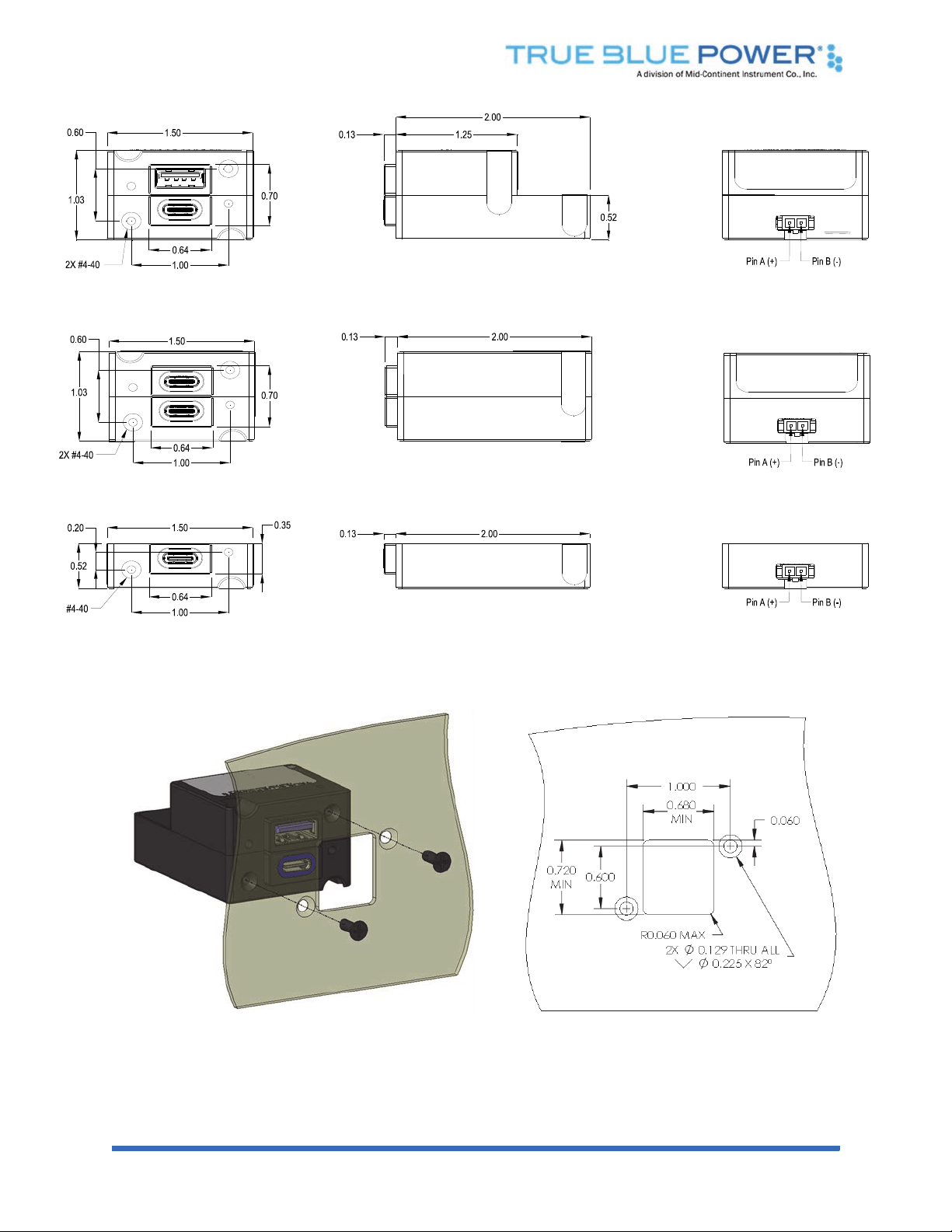
Panel Cutout Detail
Figure 3.2
TA360 Outline Drawing
(Dual port, Type A/C version shown)
Figure 3.3
TA360 Outline Drawing
(Dual port, Type C/C version shown)
Figure 3.4
TA360 Outline Drawing
(Single, Type C version shown)
Figure 3.5
Dual Port Rear Mount Installation
Rev A, October 18, 2019 12 Manual Number 9019411
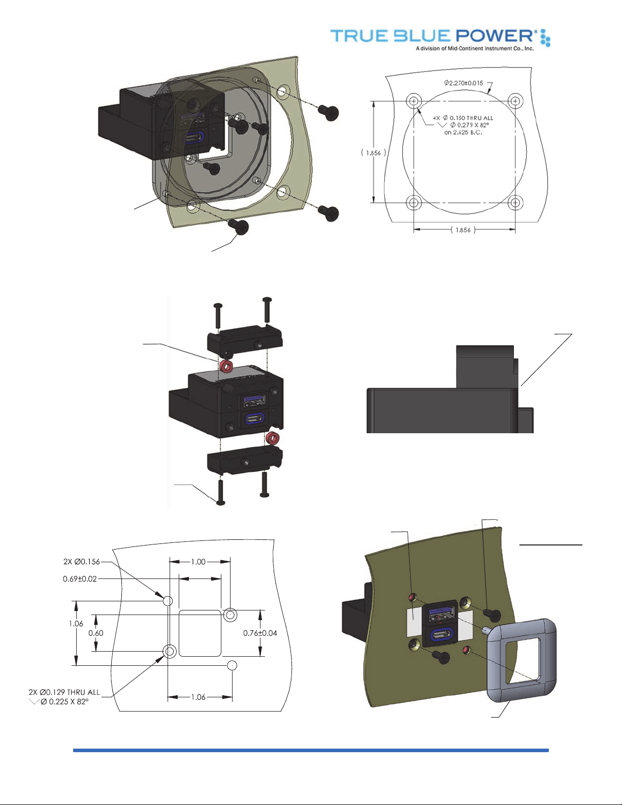
Figure 3.6
Dual Port Instrument Mount Installation
Step 3: place unit in panel
cutout and secure with
screws (x2)
provided with unit
Step 4: place adhesive on
panel (x2) in locations
shown and remove backing
Step 5: align pins on rea
r
of cover plate into holes on
panel and press firmly
Figure 3.7
Dual Port Rear Mount Installation with Cover Plate
Step 1: attach adapte
r
plate to unit
Step 2: attach adapter plate to
panel
Latch and front of unit - flush
Flush Detail
Step 1: install
grommets
Step 2: place screw through
mounting plate (x4) with front
latches set flush to front of unit
(see detail view)
Rev A, October 18, 2019 13 Manual Number 9019411
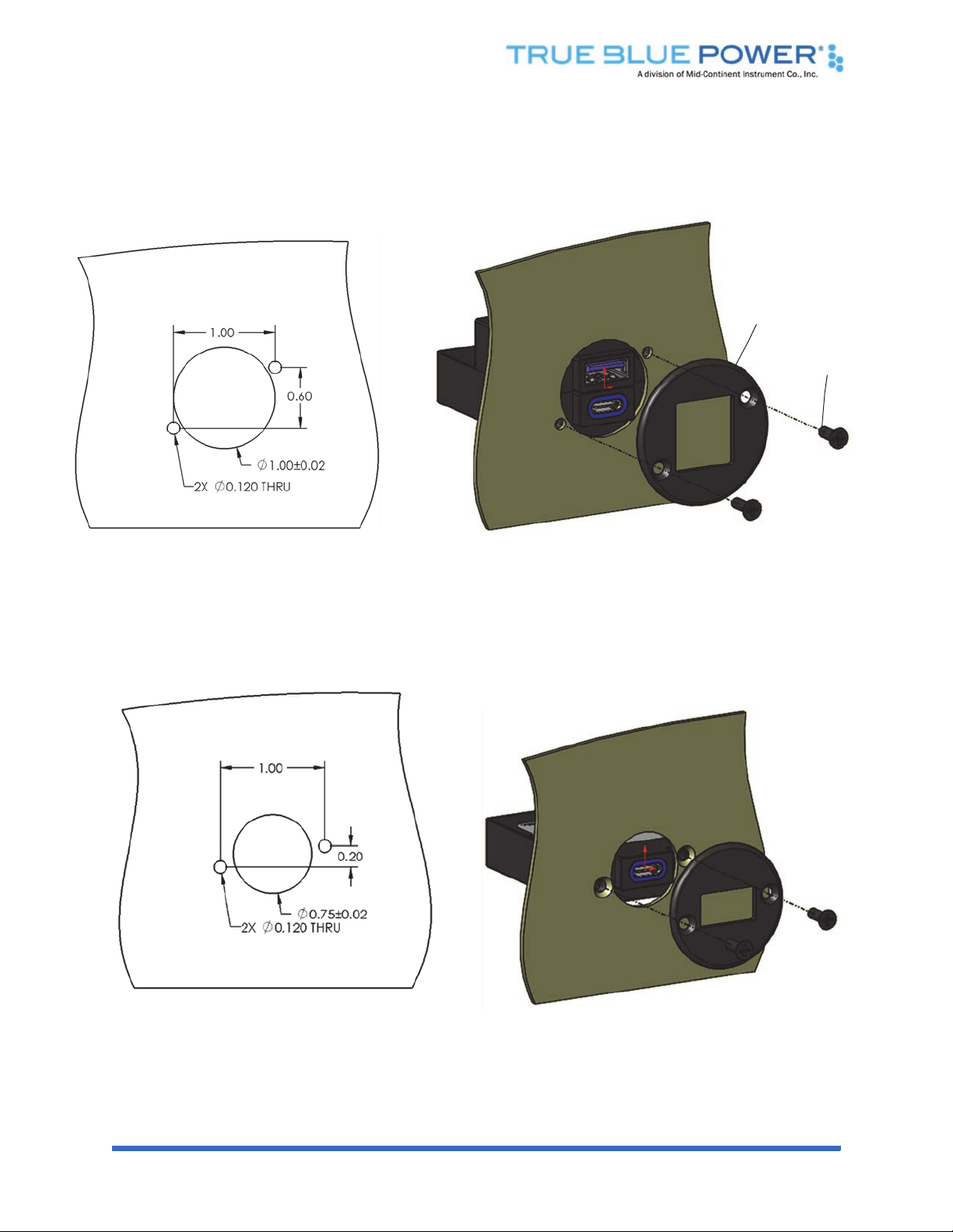
Figure 3.8
Dual Port Rear Mount Installation with Circular Cover Plate
Circular Cover Plate is
Ø1.50
Note: screws provided
with unit
Figure 3.9
Single Port Rear Mount Installation with Circular Cover Plate
Rev A, October 18, 2019 14 Manual Number 9019411
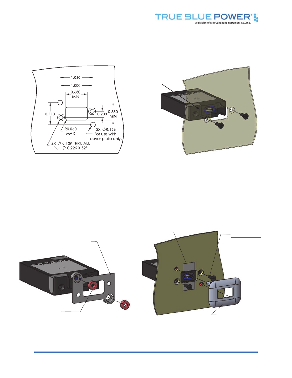
Figure 3.10
Single Port Rear Mount Installation
Figure 3.11
Single Port Rear Mount Installation with Cover Plate
Step 1: Insert grommets
Step 2: Place mounting
plate over port
protrusion
Step 3: place unit in panel cutout and
secure with screws (x2)
provided with unit
Step 4: place adhesive on
panel (x2) in locations
shown and remove
backing
Step 5: align pins on rear of cover
plate into holes on panel
and press firmly
Port protrusion
toward top

Rev A, October 18, 2019 15 Manual Number 9019411
SECTION 4 OPERATION
4.1 ELECTRICAL PERFORMANCE
The TA360 USB Power Delivery Charging Port converts an aircraft (DC) input voltage within the range
specified to a voltage between 5VDC and 20VDC on the output, depending on the level negotiated
between the device and the charger. This output power is independently applied to single or dual USB-C
connectors in accordance with the USB 3.1 and USB Power Delivery standards.
For the dual port option that includes a USB Type-A connector, the USB D+ and D- data lines
communicate with the USB portable device to tell the device it is a dedicated charging port (DCP),
capable of a higher current than a standard USB port. This allows the USB portable device to draw up to
3.0 Amps at 5VDC.
The unit is designed as a DC-to-DC converter with a series switch on each output to regulate current
applied to that output. Each series switch independently reduces the output current to a safe level if the
USB portable device draws excess current, is shorted or has a fault.
If the temperature of the TA360 becomes elevated due to a fault or excessive load, the device will
seamlessly communicate with the USB portable device to lower the charge current. This allows the device
to continue charging while the unit returns to a temperature within designed limits. When the temperature
returns to a safe level the TA360 will automatically reestablish the higher charge current level with the
device and continue charging.
4.2 PROTECTIVE FEATURES
4.2.1 Over-Current Protection
The TA360 monitors power individually on each port. During an over-current condition, the
output power is disabled until the over-current condition is resolved with the connected
device.
4.2.2 Short Circuit Protection
The TA360 will survive a short circuit event without permanent damage. The unit disables
output power as it would for over-current protection until the short is removed.
4.2.3 Low Input Voltage Shutdown
If the input voltage applied to the TA360 drops below 22 VDC the unit will shut down until the
applied voltage returns to a level within range.
4.2.4 Over-Temperature
When the internal temperature of the TA360 exceeds designed thresholds, the unit will shut
down and stop providing power. When the temperature returns to an acceptable level the unit
will automatically begin providing power as requested.
4.2.5 Reverse Polarity
The TA360 will protect itself against being installed with the input power wires reversed.

Rev A, October 18, 2019 16 Manual Number 9019411
SECTION 5 CONFORMANCE
5.1 CONTINUED AIRWORTHINESS STATEMENT
No periodic scheduled maintenance or calibration is necessary for continued airworthiness of the TA360
Series USB PD Charging Port. If the unit fails to perform to specifications, the unit must be removed and
serviced by Mid-Continent Instruments and Avionics or their authorized designee.
5.2 ENVIRONMENTAL QUALIFICATION STATEMENT
MODEL NUMBER: TA360 Series PART NUMBER: 6430360-( )
NOMENCLATURE: USB Power Delivery Charging Port CERTIFICATION: FAA TSO-C71
MANUFACTURER: True Blue Power, a division of Mid-Continent Instrument Co., Inc.
ADDRESS: 9400 E. 34
th
St. North, Wichita, KS 67226, USA.
MANUFACTURERS SPECIFICATIONS:
Minimum Performance Specifications: TS742, TDS742
Environmental Test Standard: RTCA DO-160, Revision G, dated 12/08/10
Qualification Test Reports: QTR3904-3908, QTR3913, QTR3915-3918, QTR2621,
QTR3925-3926
CONDITIONS SECTION DESCRIPTION OF TEST
Temperature and Altitude 4 Category F1
Temperature Variation 5 Category S2
Humidity 6 Category B
Operational Shock and Crash Safety 7 Category B
Vibration 8 Category R, Curves C, C1
Explosion 9 Category X
Waterproofness 10 Category X
Fluids 11 Category X
Sand and Dust 12 Category X
Fungus 13 Category F
Salt Spray 14 Category X
Magnetic Effect 15 Category Z
Power Input 16 Category B(XX)
Voltage Spike 17 Category B
Audio Freq Conducted Susceptibility 18 Category R
Induced Signal Susceptibility 19 Category X
Radio Frequency Susceptibility 20 Category X
Emission of Radio Frequency Energy 21 Category H
Lightning Induced Transient Susceptibility 22 Category X
Lightning Direct Effects 23 Category X
Icing 24 Category X
ESD 25 Category A
Fire, Flammability 26 Category C
REMARKS:
This manual suits for next models
6
Table of contents
Other True blue power Batteries Charger manuals

True blue power
True blue power TT43 Technical Document

True blue power
True blue power TA102 Technical Document

True blue power
True blue power TWC15 Series User manual

True blue power
True blue power TA202 Series Technical Document

True blue power
True blue power TA202 Series Technical Document

True blue power
True blue power TA102 Technical Document


