Trumeter 9100 User manual

017453-01 Issue 4.1 12/11
9100
Predetermining Counter / Ratemeter
Zähler / Geschwindigkeitsmesser
mit Vorwahleinrichtung
Compteur / Tachymètre à
présélection
Definizione del Contatore /
Misuratore di Frequenza
Contador / Tacómetro con
preselección
English
Page 2
Deutsch
Seite 8
Français
Page 14
Español
Página 20
Italiano
Pagina 26
Page 32
Seite 32
Pagina 32
Page 36
Seite 36
Pagina 36
Dimensions, Abmessungen, Dimensiones,
Dimensioni
Specifications, Spezifikation, Caracteristiques
Techniques, Especificación, Specifiche
017453-01 Issue 4.2 09/16
www.GlobalTestSupply.com
Find Quality Products Online at: sales@GlobalTestSupply.com

2
OVERVIEW
The 9100 is a versatile multi-function counter/ratemeter and
process controller. Features include:-
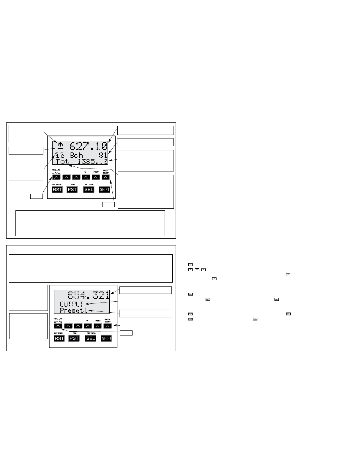
• LCD three-row dot matrix display with backlight;
• simultaneous display of instantaneous, batch and total
counts;
• seven count modes;
BASIC OPERATION
Inputs A and B receive count pulses. The 9100 counts these
and also measures the rate at which the pulses are arriving
on input A only (input B in quadrature x 1 mode).
The progress of the count or the rate is shown on the front
panel display according to the mode and the scale values
you program into the unit.
Outputs R1, R2 and R3 change state when the count or the
rate becomes equal to a preset value (P1, P2 or P3) which
you set for each output. Each of the three outputs can be
programmed to respond either to a count value or a rate
value, as required. Each output can be independently
programmed to remain in the changed state for an amount
of time which you can set (the ‘on time’) - this is called
Pulsed Mode - or to remain in the changed state until the
end of a complete count cycle - this is called Latched Mode.
The normal sequence for outputs, in count mode, is for P1
and P2 to be set between zero and P3, since the value of
P3 determines the end of a cycle of counting; outputs 1 and
2 will therefore change state at preset points within the
count cycle. If you have chosen ‘automatic reset’ mode,
then reaching the end of a count cycle resets all latched
outputs to their initial state. If you have chosen ‘manual
reset’ mode, then latched outputs remain latched until the
counter is reset from the front panel or by a pulse on the
External Reset input.
Output 1 can alternatively be set up as a batch counter,
which you can preset to operate when a certain number of
count cycles have been completed.
Output 2 can alternatively be set up as a ‘motion monitor’.
In this mode, if no count pulse has been received for 12.8
seconds (equivalent to 4.7 rpm when using a shaft
encoder), then relay R2 operates to provide an indication
that the process has stopped. When the next pulse is
received, R2 releases and timing starts again.
• comprehensive prescaling for direct display in units of
your choice;
• three fully programmable relay outputs for process
control;
• simple, straightforward visual programming;
• programming in any of four European languages.
COUNT TYPES
UNI + DIR
Count is incremented or decremented by input A. Direction
is determined by input B:-
Input B open - Increment
Input B closed - Decrement
A+B
Count is incremented by either input A or input B.
A-B
Count is incremented by input A and decremented by B.
A/B
Count is incremented by input A. Display is derived from
input A divided by input B. Manual reset (keyboard or
remote) is required to clear the B count value.
Quadrature Counting Modes
For all quadrature modes, the phase of input A must lag or
lead that of input B by 90 degrees.
For an incrementing count, A must lead B by 90 degrees.
For a decrementing count, A must lag B by 90 degrees.
Quadrature x1
Count is incremented or decremented on the rising edge of
input B.
Quadrature x2
Count is incremented or decremented on the rising and
falling edges of input A.
Quadrature x4
Count is incremented or decremented on the rising and
falling edges of both inputs.
Note: In the quadrature counting modes, use electronic
sensors because inputs A and B are not debounced.
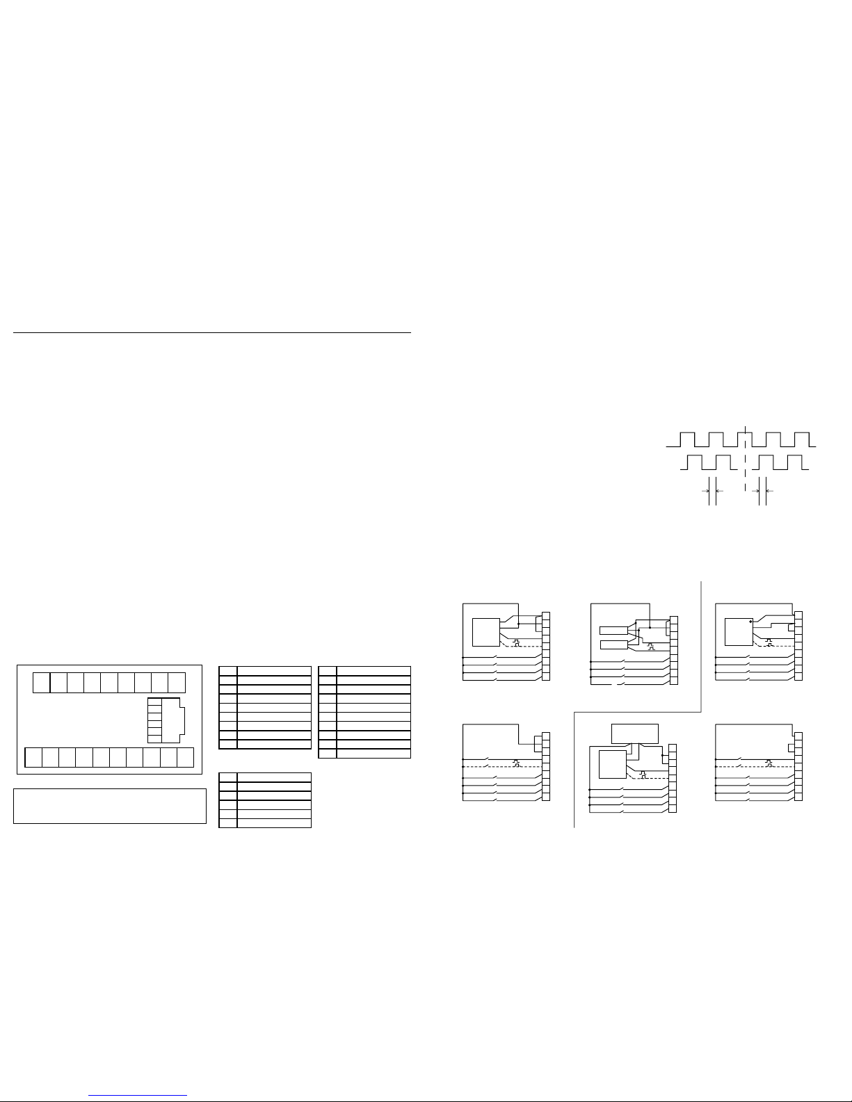
EXTERNAL CONNECTIONS
Two terminal blocks are provided at the back of the counter,
arranged as shown. The terminal strips may be unplugged
from the counter to facilitate easy wiring.
To ensure correct operation this unit must be installed in
accordance with the “Recommended Installation
Procedures for Micro-Processor Based Products” -
Trumeter product number 015580-01.
23456 7 89
1918
17
1615
14
13
1211
10
1
5
6
4
3
2
1
CN1
CN2
CN3
Connectors from rear
Connector CN1 Connector CN2
Connector CN3
1DC Output 12V
2DC Output 0V
3Signal Common
4Count Input A
5Count Input B
6External Reset
7Keyboard Disable
8Count Inhibit
9External Print
10 AC Mains L
11 AC Mains N
12 N.C.
13 Relay R1 Common
14 Relay R1 Contact
15 Relay R2 Common
16 Relay R2 Contact
17 Relay R3 Common
18 Relay R3 Contact
19 No Connection
1Receive (RX)
2Transmit (TX)
30V
4N.C.
5N.C.
6N.C.
Sink Mode Source Mode
1
2
3
4
5
6
7
8
9
Sensor 1
Sensor 2
+12v
0v
Signal (A)
(Sign al B)
External Reset
Keyboard Disable
Count Inhibit
External Print
Illustrating use of two sensors to provide
A and B signals (sink mode depicted).
1
3
4
5
6
7
8
9
Sensor
Signal (A)
(Sign al B)
+
v 0v
External Reset
Keyboard Disable
Count Inhibit
External Prin t
External Supply
10 to 30v dc
2
Illustrating use of external power supply
(source mode depicted).
+
1
2
3
4
5
6
7
8
9
Sensor
+12v
0v
Signal (A)
(Sign al B)
+
External Reset
Keyboard Disable
Count Inhibit
External Prin t
(NPN output devices)
1
2
3
4
5
6
7
8
9
+12v
0v
Signal (A)
(Sign al B)
External Reset
Keyboard Disable
Count Inhibit
External Print
Contact clos ure
device(s)
(Contact closure devices)
1
2
3
4
5
6
7
8
9
Sensor
+12v
0v
Signal (A)
(Sign al B)
External Reset
Keyboard Disable
Count Inhibit
External Print
(PNP output devices)
1
2
3
4
5
6
7
8
9
+12v
0v
Signal (A)
(Sign al B)
External Reset
Keyboard Disable
Count Inhibit
External Print
Contact closure
device(s)
(Contact closure devices)
3
CONNECTION OF SENSORS
A “sensor” can be a 3-wire proximity switch, 3-wire photocell
or incremental shaft encoder etc.
3-wire devices should use input A as the single input for
unidirectional counting.
For bi-directional (quadrature) counting, input A and input B
must be 90° out of phase, lag or lead.
Two 3-wire devices connected to inputs A and B
respectively can provide signals for bi-directional counting
(either for quadrature or A-B modes).
When signal is generated by contact closure devices,
choose “contact cls” in programming. This ensures
adequate de-bouncing but limits the count rate to 30 counts
per second.
The external control inputs are permanently set in de-
bounce mode but may also be driven by electronic devices,
subject to the 30 count per second limitation.
TIMING DIAGRAM
The timing diagram below illustrates how the direction of
count is controlled in quadrature mode by the lead or lag of
the pulses on Input A with respect to Input B.
A
B
Count up Count down
90º Lead 90º Lag
COMMUNICATIONS PORT (CN3)
RS232-C communication is used to allow connection of the 9100 to a printer. Printouts of the user text (12 characters) and
count or rate value plus engineering units may be initiated from the keyboard or external printer input.
Baud rate, number of stop bits and number of print copies are selected in program mode.
If the printer type is set to IBM/Epson, a PC can be used to remotely execute a Print or Reset:Connect the PC’s serial port
transmit pin to the 9100’s RJ11 receive pin, and send an ASCII P (50 Hex) to execute a Print or an ASCII R (52 Hex) to
execute a Reset.
The data may be read into a PC by connecting the RJ11 transmit pin to the PC’s serial port receive pin, instead of a printer.
In Manual Reset mode only, the 9100 can be automatically reset as soon as a Print is executed (by the keyboard or
externally). This feature can be turned on or off using the Comms/Print menu (see page 6).
Please note:
Any signal cables connected to this device must not exceed
30 metres in length.
If any signal cables are installed that are routed outside the
building, it will be necessary to install additional surge
protection devices.
www.GlobalTestSupply.com
Find Quality Products Online at: sales@GlobalTestSupply.com

4
FRONT PANEL FUNCTIONS
RUN MODE
This symbol is either an
up- or down- arrow
showing the direction of
count, or a letter ‘R’ for
Rate.
Line 1 displays Count value or Rate
value, as determined by <Shift-Digit 1>.
Line 2 displays Batch count, unless
disabled during programming.
Line 3 displays Total count, unless
disabled during programming,
Pressing <Shift-Digit 6> sequentially
causes this line to display the preset
value for output 1, then 2, then 3, then
back to Total.
Shows “Tot” for Total count.
Shows the following during display of
preset values:-
CP1,2 or 3 for count outputs.
US1,2 or 3 for Underspeed outputs.
OS1,2 or 3 for Overspeed outputs.
BP1 for Batch count output.
MM2 for Motion Monitor output.
NA1,2 or 3 for unconfigured outputs.
These symbols show
which relays are
operated. In this
example, 1 and 2 are
operated, whilst 3 is not
operated.
Minus sign for negative
values.
Digit 6
Keyboard:-
Keyboard:-
Digit 1
Digit 6
Digit 1
Digit keys 1 to 6 and the SEL key do not have any function in this mode except in combination with SHIFT.
RST resets the count value PST enters the PRESET programming mode
Shift-RST resets the Batch count value Shift-PST enters the main (PGM) programming mode.
Shift-SEL resets the Total count value.
Shift-Digit 1 toggles the line 1 display between Count value and Rate value.
Shift-Digit 2 causes the current count values to be printed.
Shift-Digit 6 cycles the line 3 display between Total count and the preset values for outputs 1,2 and 3.
From RUN mode, press PST to enter limited PRESET programming, or SHIFT-PST to enter full PGM program mode.
In both programming modes, the following keys are active:
Digit 1 steps through the available options in the menu.
SEL selects the option displayed. This may be a parameter or the next menu in the tree.
RST escapes back one level in the menu tree.
PST exits back to RUN mode from anywhere within the menu tree.
Where the SELected option is a text or numeric value, Digit keys 1 to 6 are available to modify the value.
Shift-Digit 3 toggles the minus sign on and off for the line 1 display.
This example shows that
the OUTPUT programming
menu has been selected
and that for the option
chosen (Preset 1) the
value currently stored is
654.321. The value can be
altered using the digit keys.
Pressing SEL at this point
makes the displayed value
current and blanks line 1.
You can then select
another option.
(Example, use the digit 1
key to step on to Preset 2).
Line 1 displays any numeric value
associated with the selection.
Line 2 displays the title of the current
menu.
Line 3 displays the option selected in
the current menu.
PROGRAMMING MODES
5
CUT TO LENGTH APPLICATION
Process
• Run machine.
• Slow when nearing required length.
• Stop at required length and cut.
• Repeat until roll/magazine etc. is empty.
• Stop.
• Manually reload roll/magazine etc. and restart.
Utilise:-
• Output 1 to power machine at normal speed.
• Output 2 to reduce machine speed.
• Output 3 to stop machine and operate guillotine.
Program:-
• Count and Input types to suit sensors used,
• Prescalers to suit measurement units required,
• Reset type to Automatic.
• Output 1:-
- Output type to Batch.
- Preset value equal to number of lengths on roll.
- On-time to zero (latched).
• Output 2:-
- Output type to Count
- Preset value equal to length minus slow-feed length.
- On-time to zero (latched).
• Output 3:-
- Output type to Count.
- Preset value equal to length required.
- On-time sufficient for guillotine operation.
• Relay Condition for each output: to suit machine
operating circuitry.
CONVENTIONS USED IN THE PROGRAMMING TREE DRAWING
(see page 6)
Step through options using Digit 1 key.
Use digit increment keys to set up a value.
To programme the User Text, the left 6 characters are cycled using the keys, and the right 6 characters are cycled
using SHIFT and keys together.
The user characters will cycle in the following sequence:
–, ‘dot’, /, 0 - 9, A - Z, ‘space’
Select displayed option. This may be a parameter or the next menu along the tree.
On pressing at the end of a branch (represented above by being within the box boundary) you are returned to the
previous menu level.
Additional Operations
Escape back one level. All the settings which have been chosen by are retained.
Exit Program mode. All settings chosen by are retained.
VOLUMETRIC DISPENSING /FLUID
BLENDING APPLICATION
Process
• Receive signal from conveyor system.
• Stop conveyor and open valve 1
• Close valve 1 and open valve 2
• Close valve 2 and open valve 3
• Close valve 3 and start conveyor system.
Utilise:-
• External Reset input to receive signal from conveyor.
• All relays at rest to stop conveyor and operate valve 1.
• Output 1 to transfer to valve 2
• Output 2 to transfer to valve 3
• Output 3 to close all valves and start conveyor.
Program:-
• Count and Input types to suit sensors used,
• Prescalers to suit measurement units required,
• Reset type to Manual.
• Output 1:-
- Output type to Count.
- Preset value equal to quantity of fluid from valve 1.
- On-time to zero (latched).
• Output 2:-
- Output type to Count.
- Preset value equal to quantity of fluid from valve 2 +
valve 1.
- On-time to zero (latched).
• Output 3:-
- Output type to Count.
- Preset value equal to quantity of fluid from valve 3 +
valve 2 + valve 1.
- On-time to zero (latched).
• Relay Condition for each output: to suit operating circuitry
for conveyor and valves.
www.GlobalTestSupply.com
Find Quality Products Online at: sales@GlobalTestSupply.com

6
SEL
SEL
SEL
SEL
SEL
SEL
SEL
SEL
SEL
SEL
SEL
SEL
SEL
SEL
SEL
SEL
SEL
SEL
SEL
SEL
SEL
SEL
SEL
SEL
SEL
SEL
SEL
SEL
SEL
SEL
SEL
SEL
SEL
SEL
SEL
SEL
SEL
SEL
SEL
SEL
SEL
SEL
SEL
SEL
SEL
SEL
SEL
SEL
SEL
SEL
SEL
SEL
SEL
SEL
SEL
SEL
SEL
SEL
SEL
SEL
SEL
SEL
SEL
SEL
SEL
SEL
SEL
SEL
- - - - - - - - - - - - to
ZZZZZZZZZZZZ
1 to 9
0.01 to 99.99
0 to 999999
SHIFT
+
PST
Printer Type
User Text
Stop Bits
Baud Rate
+ Reset
SEL
SEL
IBM / Epson
Panel
SEL
SEL
1
2
SEL
SEL
SEL
SEL
2400
Off
4800
On
Count
SEL
SEL
SEL
SEL
SEL
Underspeed
Overspeed
Batch
Off
Norm Closed SEL
SEL
Norm Open
Input Type
Reset Type
Reset Point
Prescaler
Mode
Operation
Display
Output
Program
Language
English
Deutsch
Francais
Espagnol
Count Type
Eng Units
Decimal Pt
Decimal Pt R
Comms/Print
Backlight
Batch
Totaliser
Preset 1
Preset 2
Preset 3
Electronic
Contact Cls
Automatic
Manual
To Zero
To Preset 3
SEL
SEL
SEL
SEL
SEL
SEL
SEL
SEL
Centimetres
Metres
Inches
Feet
Yards
Litres
Gallons
None
0
0.0
0.00
0.000
On
On
Off
Off
Preset Value
On Time/Hyst
Output Type
Rly Condition
Uni + Dir
A + B
A - B
A / B
Quadrature x1
Quadrature x2
Quadrature x4
None
Multiplier
Divider
Rate Multiply
(0.00 to set latched)
0.00250 to 9.99999
0.00250 to 9.99999
1 to 9999
Motion Mon
MODE
PGM
OUTPUT
OPERATION
DISPLAY
SHIFT
No of Copies
PROGRAMMING TREE
7
PST
Output
Output 1
Output 2
Output 3
0 to 999999
PRESET PROGRAMMING
MODE PROGRAMMING
CONSIDERATIONS
• Choose count type appropriate to your application (see
descriptions on page 2).
• Choose type of input to suit your type of sensor:
- ”Electronic” gives a fast input capability: up to 10kHz
repetition rate.
- “Contact closure” has additional de-bouncing and is
limited to 30Hz.
• Choose type of reset required:
- “Automatic” resets all latched relays on completion of
cycle,
- “Manual” requires a reset action from the front panel or
the external input.
• Choose reset point:
- “To P3” starts the cycle at P3 and completes at zero.
- “To zero” starts the cycle at zero and completes at
preset value P3.
• Choose multiplier or divider and/or rate multiplier to
determine the units in which your basic count will take
place.
Divider is available for instances where a multiplier would
be inexact. (example: divide by 3 is exact, whereas multiply
by 0.33333 cannot be). Rate multiply is available to modify
the basic count rate unit of 1 pulse per minute. (example:
multiply by .01667 (1/60) to convert to seconds).
INVALID Message
The word INVALID appears on the top line under two
conditions.
If the counting multiplier prescaler is set to less than
0.00250. Enter a value higher than this value.
If the reset type is Automatic AND the ON time for R3 is set
to latch. For Automatic reset, enter a pulse ON time for R3.
Alternatively, set up for manual reset.
OUTPUT PROGRAMMING
CONSIDERATIONS
• Decide, for each of the three relay outputs, whether the
relay state will depend upon a Count value, or upon a
Rate value.
• Choose which output to configure (R1, R2 or R3).
• Note that if R2 has been configured in the Operation
menu as Motion Monitor, choosing R2 here produces a
warning box and the choice of removing the option.
For each output:
• Choose COUNT output type if a change of state must
depend on reaching a set Count value.
• Choose OVERSPEED or UNDERSPEED (see below) if a
change of state must depend on reaching a set Rate
value.
• Choose OFF if the output is not required.
• Choose PRESET VALUE and use the digit keys to set the
value required.
• Choose the at-rest condition of the relay contact (open or
closed)
• Note that output 1 is configurable to depend on the value
of Batch count, if required. This menu option does not
appear when programming the other outputs.
• Note that output 2 is configurable as a MOTION
MONITOR. This is programmed in the OPERATION
menu.
If COUNT output type is chosen:
• Choose ON TIME/HYST and use digit keys to set the On-
time value required.
Entering a value determines the length of time the relay
remains operated before releasing.
Entering zero determines that the relay will not release
until a Reset is performed (latched mode).
If RATE output type is chosen:
• Choose ON TIME/HYST and use digit keys to set the
Hysteresis value required.
Entering a value determines the difference which must
occur in the rate value for the relay to release.
• In OVERSPEED, the relay operates when the rate rises
above the preset value and releases when the rate falls
below the preset value by the amount of Hysteresis.
• In UNDERSPEED, the relay operates when the rate falls
below the preset value and releases when the rate rises
above the preset value by the amount of Hysteresis.
Entering zero hysteresis determines that the operate and
release points are the same.
OPERATION PROGRAMMING
CONSIDERATIONS
• Choose the decimal point position for the Count and
Totaliser displays. (lines 1 and 3)
• Choose the decimal point position for the Rate display
(line 1 when in Rate mode).
• Choose what engineering units need to appear on
printouts.
• Decide whether an output (Motion Mon) is needed to
indicate whether your application has stopped. Choosing
this option configures output 2 as Motion Monitor.
• Set up operating parameters for the printer and any user
text you wish to appear in the printout.
• To change user text, press Digit keys 1 to 6 for the six left
characters and Shift + Digit keys 1 to 6 for the six right
characters.
• Decide how the front panel display is to appear during
operation (display menu).
www.GlobalTestSupply.com
Find Quality Products Online at: sales@GlobalTestSupply.com

120mm (4.72")
72mm (2.83")
68mm (2.68")
72mm (2.83")
68 x 68mm
(2.68" x 2.68"
+0.02" - 0")
+0.7 - 0mm
Dimensions, Abmessungen, Dimensiones, Dimensioni
www.GlobalTestSupply.com
Find Quality Products Online at: sales@GlobalTestSupply.com
Table of contents
Other Trumeter Cash Counter manuals

Trumeter
Trumeter Durant E4148793 User manual

Trumeter
Trumeter 7010 User manual

Trumeter
Trumeter 6300 User manual

Trumeter
Trumeter 7931 User manual

Trumeter
Trumeter MULTICOUNT User manual

Trumeter
Trumeter EMP-9100 User manual

Trumeter
Trumeter 898 Series User manual

Trumeter
Trumeter 34 Series User manual

Trumeter
Trumeter FALCON HED251-R User manual

Trumeter
Trumeter 7911 User manual