Product description
Functions and operating modes
Hans Turck GmbH & Co. KG | T +49 208 4952-0 |
[email protected] | www.turck.com
V02.00 | 2022/08 | 94.1.1 Display and control elements
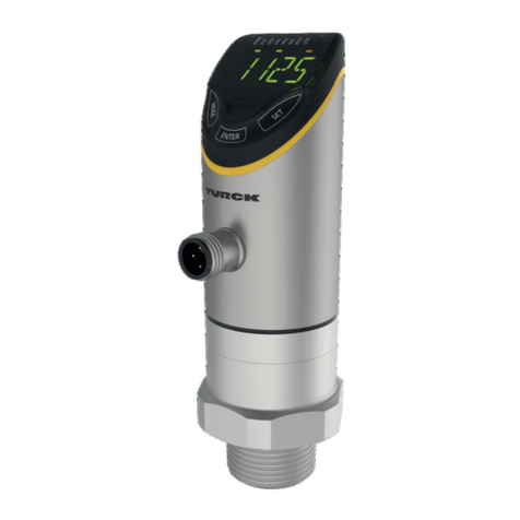
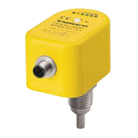
The device is equipped with three touch pads, an LED bar and status LEDs on the front. This en-
ables the user to set all essential functions and properties directly on the device and read the
actual process values and taught switch points.
4.2 Properties and features
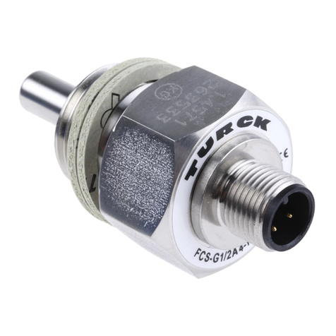
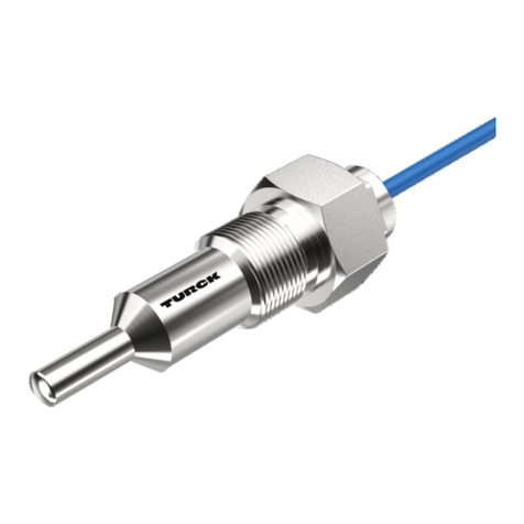
nFlow monitoring for liquid media
nVariants with a thread adapter for process connection
nSensor housing material 1.4404 (316L)
nMaterial in contact with medium 1.4571 (316Ti)
nProtection classes IP66, IP67, IP69K
nProcess value display via 11-digit LED indicator bar
nTouchpad and/or data storage lock function
nSetting via touchpads or IO-Link interface
nCalibration of the flow speed (setting the switching point/display area) via the teach-in
function
nDeltaFlow function: the memory function for teach-in values is only released after the warm-
up phase with constant flow
nOutput 1 — flow: switching output or IO-Link interface
nOutput 2 — temperature: switching output
nOutput type: configurable NC/NO contact
nConfigurable output configuration: PNP/NPN/Auto Detection
4.3 Operating and display functions
The user can configure and operate the device via three touch pads ([ENTER], [MODE] and
[SET]) on the front. An 11-digit LED bar aids parameterization and displays the current flow or
temperature values (as selected) in operating mode. Five LEDs indicate the switching status
and device status.
4.4 Operating principle
The flow sensors operate calorimetrically. The function is based on the thermo-dynamic prin-
ciple. When the medium is flowing, thermal energy is dissipated at the sensor. The resulting
temperature on the sensor is measured and compared to the medium temperature. The flow
status can be derived directly from the determined temperature difference: The greater the en-
ergy dissipation, the higher the flow speed or flow rate.
4.5 Functions and operating modes
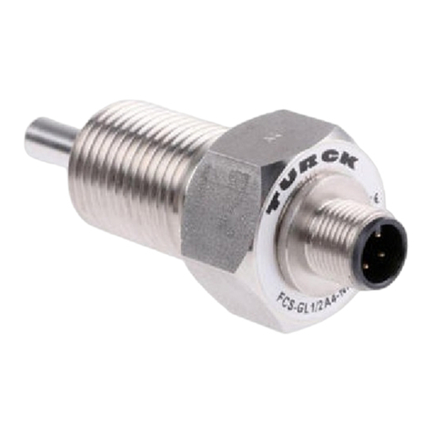
The FS100…-2UPN8 compact flow sensors monitor the flow speed of liquid media (type
FS1…-…L-) as well as the media temperature to determine whether configurable limit values
are exceeded or undershot. The devices show the recorded flow and temperature values on the
front via status LEDs and an LED bar. The two switching outputs can optionally be used as nor-
mally open or normally closed contacts. If the auto detection function is activated, the sensor
automatically detects and activates the relevant type of output (PNP/NPN). When operating
with an IO-Link master, one of the two digital outputs can also be used as a bidirectional, serial
IO-Link interface.
4.5.1 Flow monitoring
The flow speed is detected by a calorimetric sensor in the flow channel and evaluated by the in-
tegrated evaluation electronics. The current flow value is displayed via the LED bar and—when
connected to an IO-Link master—is output via a communication signal.
The switching output Out1 (Flow) changes its switching status when the set switching point is
reached as a result of the reducing flow rate. If the flow rate increases, the switching status
changes when the switching point is undershot by the hysteresis.
