manuals.online logo
Brands
  1. Home
  2. •
  3. Brands
  4. •
  5. Dungs
  6. •
  7. Control Unit
  8. •
  9. Dungs DMK 5040 Service manual

Dungs DMK 5040 Service manual

1 … 8
M/CD • Edition 10.13 • Nr. 243 529
Umgebungstemperatur
Ambient temperature
Température ambiante
Temperatura ambiente
-15 °C… +70 °C
Betriebs- und Montage-
anleitung
Motorklappe
Typ DMK
Nennweiten
DN 40 - 125
Operation and assembly
instructions
Motor valve
Typ DMK
Nominal diameters
DN 40 - 125
Notice d'emploi et de
montage
Vanne papillon motorisée
type DMK
Diamètre nominal
DN 40 - 125
Istruzioni di esercizio di
montaggio
Valvola motorizzata a farfalla
Tipo DMK
Diametri nominali
DN 40 - 125
Einbaulage beliebig.
Technische Daten des Stellan-
triebes beachten!
Any installation position.
Refer to technical data of
actuator!
Max. Betriebsdruck
Max. operating pressure
Pression de service maxi.
Max. pressione di esercizio
pmax. = 500 mbar (50 kPa)
DMK 5040 - 5125
nach / acc. / selon / a norme
DIN 3394 T2
Siehe Stellantrieb!
See actuator
Voir servomoteur
Vedere attuatore
 
 
 
 
 
 
  

 
 
  
  
  
 
   
Position de montage au choix.
Respecter les caractéristiques
techniques du servomoteur!
Posizionamento facoltativo.
Osservare idati tecnici dell`
attuatore!
B
B
B
B
Familie 1 + 2 + 3
Family 1 + 2 + 3
Famille 1 + 2 + 3
Famiglia 1 + 2 + 3
max. Dierenzdruck
max. dierential pressure
Pression diérentielle max.
Max. pressione dierenziale
250 mbar (25 kPa)
max. Stellwinkel
max. disk angle
Angle de réglage max.
Angolo regolazione max.
90°
Technische Daten des Stellantriebes
beachten!
Refer to technical data of actuator.
Respecter les caractéristiques tech-
niques du servomoteuer.
Osservare i dati tenici del attuatore!
[mbar]
DIN 3394
B

➞ ➞ ➞ ➞
➞ ➞ ➞ ➞
➞ ➞ ➞ ➞
Gas Gaz
∆p ≤250 mbar





2 … 8
M/CD • Edition 10.13 • Nr. 243 529
max. Drehmomente / Systemzubehör
max. torque / System accessories
max. couple / Accessoires du système
max. coppie / Accessorio di sistema
M 5
5 Nm
M 6
7 Nm
G 1/8
5 Nm
G 1/4
7 Nm
G 1/2
10 Nm
G 3/4
15 Nm
M 8
15 Nm
M 4
2,5 Nm
Gerät darf nicht als Hebel benutzt werden.
Do not use unit as lever.
Ne pas utiliser la vanne comme un levier.
L'apparecchio non deve essere usato come leva.
[Nm]
18
19
Chrome Steel ✸Made in Germany
Einbaumaße / Dimensions / Cotes d´encombrement / Dimensioni [mm]
Geeignetes Werkzeug einsetzen! Schrauben kreuzweise anziehen!
Please use proper tools! Tighten screws crosswise!
Utiliser des outils adaptés! Serrer les vis en croisant!
Impiegare gli attrezzi adeguati! Stringere le viti incrociate!
max. Drehmomente/Flanschverbindung
max. torque/Flange connection
max. couple/Joint à brides
max. coppie/Collegamento a angia
Verschluß- und Verbindungsschrauben sachgemäß anziehen.
Werkstopaarung Druckguß – Stahl beachten!
Tighten plugs and union screws properly.
Make sure of proper material combinations, e.g. diecast – steel!
Serrer les vis fermeture et de xation comme il convient.
Respecter l'appariement des materiaux moulage sous pression – acier!
Stringere in modo appropriato sia le viti di collegamento che quelle di chisura.
Prestare attenzione alla pressofusione in acciaio nell'abbinamento dei materiali.
M 16 x 65 (DIN 939) Stiftschraube
Setscrew
50 Nm Goujon
Vite per acciaio
ISO 7005-2
DN 40 50 65 80 100 125
Mmax. 610 1100 1600 2400 5000 6000 [Nm] t ≤ 10 s
Tmax. 200 250 325 400 400 400 [Nm] t ≤ 10 s
Mmax.
Mmax.
Tmax.
Tmax.
DMK 5040 DN 40
DMK 5050 DN 50
DMK 5065 DN 65
DMK 5080 DN 80
DMK 5100 DN 100
DMK 5125 DN 125
pmax.
500 mbar
500 mbar
500 mbar
500 mbar
500 mbar
A
40
40
40
40
40
40
B
93
105
125
140
160
192
C
42
48,5
59,5
67
77
89,5
D
92
98,5
109,5
117
127
139,5
IP40
IP40
IP40
IP54
IP54
IP65
IP65
E
65
65
65
90
90
80
80
F
99
99
99
136
136
120
120
G
66
114
114
149
149
124
124
a Stellanzeige für Klappenstellung.
Actuator display for valve position
Achage de la position du papillon
Indicazione regolazione per posizione farfalla
b Arretierungsschraube für Motorwelle: Gewindestift ISO 4029-M5 x 6
Innensechskant SW2,5, Punkt 4, Seite 3 beachten!
Stop screw for motor shaft: Set screw ISO 4029-M5 x 6
Socket head screw SW2, item 4, refer to page 3.
Vis d’arrêt pour arbre du moteur: Tige letée ISO 4029-M5 x 6
six pans creux SW2, point 4, respecter page 3!
Viti d’arresto per l’albero del motore: Vite lettata senza testa ISO 4029-M5 x 6
viti ad esagono incassato SW2, osservare il punto
c Bohrungenfür Motorbefestigung:ZurBefestigungsind zweiZylinderschrauben
M5 x 35 mit Muttern (selbstsichernd) erforderlich (nicht im Lieferumfang)
Holes for motor xing: Two M5 x 35 pan-head screws with (self-locking)
nuts are required for xing (not in scope of supply)
Perçage pour xation du moteur: Pour xer, on a besoin de deux vis
cylindriques M5 x 35 avec écrous (autobloquants)
(pas compris dans le détail de livraison)
Fori per il ssaggio del motorino: Per il ssaggio sono necessarie due viti
a testa cilindrica M5 x 35 con dadi (autobloccanti)
(non fanno parte della fornitura)
d Bohrungenfür Motorbefestigung:ZurBefestigungsind vierZylinderschrauben
M5 x 20 mit Muttern (selbstsichernd) erforderlich (nicht im Lieferumfang)
Holes for motor xing: Four M5 x 20 pan-head screws with (self-locking)
nuts are required for xing (not in scope of supply)
Perçage pour xation du moteur: Pour xer, on a besoin de quatre vis
cylindriques M5 x 20 avec écrous (autobloquants)
(pas compris dans le détail de livraison)
Fori per il ssaggio del motorino: Per il ssaggio sono necessarie
quattro viti a testa cilindrica M5 x 20 con dadi (autobloccanti)
(non fanno parte della fornitura)
Stellantriebe/Actuators
Servomoteurs/Attuatore
DMA 40 P.../...3
DMA 40 P.../...4
DMA 30 P.../...0
DMA 30 Q.../...3
DMA 30 Q.../...0
DMA 30 A.../...3
DMA 30 A.../...0
BB
38
A B
CD G
C
ø 6
76
E
F
40
52
122
b
a
c
b
a
d
c
ø Welle/Shaft
Arbre/Albero
8
8
8
10
10
10
10
Montage/Installation
Montage/Montaggio
c
c
c
d
d
c
c
3 … 8
M/CD • Edition 10.13 • Nr. 243 529
Ersatzteile / Zubehör
Spare parts / Accessories
Pièces de rechange / access.
Parti di ricambio / Accessori
Standard-Stellantrieb
Standard actuator
Servo-moteur standard
Motorino di regolazione standard
DMA 30 P 230/03 0
Standard-Stellantrieb
Standard actuator
Servo-moteur standard
Motorino di regolazione standard
DMA 40 P 230/02 3
Standard-Stellantrieb
Standard actuator
Servo-moteur standard
Motorino di regolazione standard
DMA 40 P 230/02 4
Potentiometer-Nachrüstsatz
Potentiometer retrot set
Kit potentiomètre
Set di equipaggiamento posteriore
potenziometro
Bestell-Nummer
Ordering No.
No. de commande
Codice articolo
226 239
226 240
238 810
240 498
Montage DMK 5040 - 5125
1. Gasversorgung unterbrechen.
2. Untere Stiftschrauben einset-
zen.
3. Dichtung einsetzen.
4. DMK einsetzen. Durchussrich-
tung beachten.
5. Obere Stiftschrauben einset-
zen.
6. Alle Schrauben sachgemäß
anziehen.
7. Anschluß des Stellantriebes:
Anleitung des jeweiligen Her-
stellers beachten!
Klappenstellung überprüfen.
8. Elektrischen Anschluß herstel-
len, Anleitung des jeweiligen
Herstellers beachten!
9. Nach Abschluß der Arbeiten
Dichtheits- und Funktionskon-
trolle durchführen.
Auf vibrationsfreien Ein-
bau achten!
Ensure that the valve is in-
stalled free of vibration!
Veiller à ce que l'appa-
reil ne subisse pas de
vibrations !
Evitare possibilità di
vibrazioni!
Assembly DMK 5040 - 5125
1. Disconnect the gas supply.
2. Insert the lower gudgeon pins.
3. Mount the seal.
4. Mount the DMK. Pay attention to
the ow direction.
5. Insert the upper gudgeon pins.
6. Tighten all pins properly.
7. Connecting the actuator:
Referto manufacturerinstruc-
tions.
Check the valve position.
8. Electrical connection:
Referto manufacturerinstruc-
tions.
9. On completion of work, perform
leak and function test.
Montage DMK 5040 - 5125
1. Couper l’alimentation en gaz.
2.
Installer les goujons letés inférieurs.
3. Mettre le joint en place.
4. Monter le DMK. Veiller au sens
du ux.
5. Installer les goujons letés supé-
rieurs.
6.
Serrer correctement toutes les
vis.
7. Montage du servo-moteur:
Respecterlesinstructions des
fabricants respectifs!
Vérier la position du papillon.
8. Pour le raccordement électri-
que.
9. Une fois les travaux terminés,
procéder à un contrôle d’étan-
chéité et de fonctionnement.
Montaggio del DMK 5040 - 5125
1. Chiudere l’alimentazione del
gas
2.
Mettere le viti prigioniere inferiori
3. Mettere la guarnizione
4. Montare il DMK osservando la
direzione del usso
5.
Mettere le viti prigioniere superiori
6. Serrare in modo appropriato tutte
le viti
7. Collegamento del motorino:
attenersi alle istruzioni del
rispettivo fabbricante!
Controllare la posizione della
farfalla.
8. Eettuare l’allacciamento elettri-
co, attenendosi alle istruzioni
del rispettivo fabbricante!
9. Dopo il montaggio eettuare un
controllo di tenuta e funzionale.
Ersatzteile / Zubehör
Spare parts / Accessories
Pièces de rechange / access.
Parti di ricambio / Accessori
Stellantrieb
Actuator
Servo-moteur
Motorino di regolazione
DMA 30 Q 230/10 0 IP54
Stellantrieb
Actuator
Servo-moteur
Motorino di regolazione
DMA 30 Q 230/10 3 IP54
Stellantrieb
Actuator
Servo-moteur
Motorino di regolazione
DMA 30 A 230/10 3 LR
DMA 30 A 115/10 3 LR
DMA 30 A 230/10 0 LR
DMA 30 A 115/10 0 LR
DMA 30 A 24/10 3 LR
Bestell-Nummer
Ordering No.
No. de commande
Codice articolo
252 721
252 723
255 039
255 041
255 042
255 044
255 482
4 … 8
M/CD • Edition 10.13 • Nr. 243 529
Durchußdiagramm 1
DMK 5040 - DMK 5125
Vmin. Klappenstellung 0°
Klappe geschlossen
Flow diagram 1
DMK 5040 - DMK 5125
Vmin. valve position 0°
Valve closed
Diagramma portata 1
DMK 5040 - DMK 5125
Vmin. posizione farfalla 0°,
con farfalla chiusa
Diagramme de débit 1
DMK 5040 - DMK 5125
Vmin. position du papillon 0°
papillon fermé
∆p [mbar]
2
3
4
5
6
1
8
10
20
30
40
60
80
100
50
0,6 0,8 10
8
642 31,0
0,4 5 7 920 30 40
ø 32
ø 40
ø 50
ø 65
ø 80
ø 100
ø 125
ø 24
50 70 90
0,6 0,8 10
8
642 31,0 5 7 920 30 40 50 70 90
∆p [mbar]
2
3
4
5
6
1
8
10
20
30
40
60
80
100
50
300 1000 2000200 400 600
100 800 4000 6000 800010000 20000
10 20 30 40 5060 8090
5040 ø 24
5040 ø 32
5040 ø 40
5080 ø 50
5080 ø 65
5080 ø 80
200 400 600
100 800 4000 6000 800010000 20000
10 20 30 40 5060 8090
Durchußdiagramm 2
DMK 5040 - DMK 5080
Klappenstellung Vmax. 90°
Klappe oen
Diagramma portata 2
DMK 5040 - DMK 5080
Posizione farfalla Vmax. 90°,
farfalla aperta
Flow diagram 2
DMK 5040 - DMK 5080
Valve position Vmax. 90°
Valve open
Diagramme de débit 2
DMK 5040 - DMK 5080
Vmax. position du papillon 90°
papillon ouvert
Arbeitsbereich
Working range
Zone de travail
Campo di lavoro
Vn [m3/h] Erdgas / Natural gas / Gaz naturel / Gas metano dv = 0,65
Vn [m3/h] Luft / Air / Aria dv = 1,00
Basis + 15 °C, 1013 mbar, trocken
Based on + 15 °C, 1013 mbar, dry
Base + 15 °C, 1013 mbar, sec
Base + 15 °C, 1013 mbar, secco
Basis + 15 °C, 1013 mbar, trocken
Based on + 15 °C, 1013 mbar, dry
Base + 15 °C, 1013 mbar, sec
Base + 15 °C, 1013 mbar, secco
Vn [m3/h] Erdgas / Natural gas / Gaz naturel / Gas metano dv = 0,65
Vn [m3/h] Luft / Air / Aria dv = 1,00
5 … 8
M/CD • Edition 10.13 • Nr. 243 529
Durchußdiagramm 3
DMK 5050 - DMK 5100
Klappenstellung Vmax. 90°
Klappe oen
Diagramma portata 3
DMK 5050 - DMK 5100
Posizione farfalla Vmax. 90°,
farfalla aperta
Flow diagram 3
DMK 5050 - DMK 5100
Valve position Vmax. 90°
Valve open
Diagramme de débit 3
DMK 5050 - DMK 5100
Vmax. position du papillon 90°
papillon ouvert
Durchußdiagramm 4
DMK 5065, DMK 5125
Klappenstellung Vmax. 90°
Klappe oen
Diagramma portata 4
DMK 5065, DMK 5125
Posizione farfalla Vmax. 90°,
farfalla aperta
Flow diagram 4
DMK 5065, DMK 5125
Valve position Vmax. 90°
Valve open
Diagramme de débit 4
DMK 5065 , DMK 5125
Position du papillon Vmax. 90°
papillon ouvert
∆p [mbar]
2
3
4
5
6
1
8
10
20
30
40
60
80
100
50
300 1000 2000200 400 600
100 800 4000 6000 800010000 20000
10 20 30 40 5060 8090
5050 ø 32
5050 ø 40
5050 ø 50
5100 ø 65
5100 ø 80
5100 ø 100
200 400 600
100 800 4000 6000 800010000 20000
10 20 30 40 5060 8090
∆p [mbar]
2
3
4
5
6
1
8
10
20
30
40
60
80
100
50
300 1000 2000200 400 600
100 800 4000 6000 800010000 20000
10 20 30 40 5060 8090
5065 ø 40
5065 ø 50
5065 ø 65
5125 ø 80
5125 ø 100
5125 ø 125
200 400 600
100 800 4000 6000 800010000 20000
10 20 30 40 5060 8090
Arbeitsbereich
Working range
Zone de travail
Campo di lavoro
Arbeitsbereich
Working range
Zone de travail
Campo di lavoro
Basis + 15 °C, 1013 mbar, trocken
Based on + 15 °C, 1013 mbar, dry
Base + 15 °C, 1013 mbar, sec
Base + 15 °C, 1013 mbar, secco
Basis + 15 °C, 1013 mbar, trocken
Based on + 15 °C, 1013 mbar, dry
Base + 15 °C, 1013 mbar, sec
Base + 15 °C, 1013 mbar, secco
Vn [m3/h] Erdgas / Natural gas / Gaz naturel / Gas metano dv = 0,65
Vn [m3/h] Luft / Air / Aria dv = 1,00
Vn [m3/h] Erdgas / Natural gas / Gaz naturel / Gas metano dv = 0,65
Vn [m3/h] Luft / Air / Aria dv = 1,00
6 … 8
M/CD • Edition 10.13 • Nr. 243 529
Flanschächen schützen.
Schrauben kreuzweise
anziehen. Auf mecha-
nisch spannungsfreien
Einbau achten.
DirekterKontaktzwischen
DMK und dem aushär-
tendem Mauerwerk, Be-
tonwänden, Fußböden ist
nicht zulässig.
Eviter tout contact direct
entre le DMK et la ma-
çonnerie, les cloisons
en béton et planchers en
cours de séchage.
Protéger les surfaces ser-
vant au montage. Serrer
les vis en croisant.Lors du
montageéviterlestension
mécaniques.
Protect ange surfaces.
Tighten screws cross-
wise. Mount tension-
free.
Do not allow any direct
contact between the DMK
and hardened masonry,
concrete walls or oors.
Proteggere le superci
della angia. Stringere le
viti in modo incrociato.
Fare attenzione al mon-
taggio che sia privo di
tensione.
Non é consentito il con-
tatto diretto fra la DMK
e murature invecchiate,
pareti in calcestruzzo,
pavimenti.
Grundsätzlich nach
Teileausbau/-umbauneue
Dichtungen verwenden.
Always use new seals
after dismounting and
mounting parts.
Après un démontage ou
une modification, utili-
ser toujours des joints
neufs.
In linea di massima, dopo
lo smontaggio e il rimon-
taggio di alcune parti,
utilizzare nuove guarni-
zioni.
Rohrleitungsdichtheits-
prüfung: Kugelhahn vor
den Armaturen schlie-
ßen.
Pipeline leakage test:
closeballvalveupstream
of ttings.
Contrôle de l'étanchéité
de la conduite: fermer
le robinet à boisseau
sphèrique avant les élec-
trovanne.
Per la prova di tenuta delle
tubature:
chiudereilrubinetto a sfera
davanti ai alla valvola.
Nach Abschluß von Ar-
beiten am DMK: Dicht-
heitskontrolle und Funk-
tionskontrolle durchfüh-
ren.
Oncompletionofworkon
the DMK, perform a leak-
age and function test.
Une fois les travaux sur le
DMK terminés, procéder
toujours à un contrôle
d'étanchéité et de fonc-
tionnement.
Al termine dei lavori
eettuati su una DMK:
predisporre un controllo
sia della tenuta che del
funzionamento.
Niemals Arbeiten durch-
führen, wenn Gasdruck
oder Spannung anliegt.
Oenes Feuer vermeiden.
Öentliche Vorschriften
beachten.
Never perform work if
gas pressure or power is
applied. No naked ame.
Observe public regula-
tions.
Ne jamais eectuer des
travaux sous pression et
ou la sous tension .Eviter
toute amme ouverte.
Observer les réglemen-
tations.
Innessun casosidebbono
eettuare lavori in presen-
za di pressione gas o di
tensione elettrica.Evitare
i fuochi aperti e osservare
leprescrizionidisicurezza
locali.
Bei Nichtbeachtung der
Hinweise sind Personen-
oder Sachfolgeschäden
denkbar.
If these instructions are
not heeded, the result
may be personal injury or
damage to property.
En cas de non-respect
de ces instructions, des
dommages corporels ou
matériels sont possible.
La non osservanza di
quanto suddetto può
implicaredanni apersone
o cose.
Arbeiten am DMK dürfen
nur von Fachpersonal
durchgeführt werden.
Seul un personnel spé-
cialisé peut eectuer des
travaux sur le DMK.
Work on the DMK may
only be performed by
specialist sta.
Qualsiasi operazione
eettuata sulle DMK deve
essere fatta da parte di
personale competente.
B
Alle Einstellungen und
Einstellwerte nur in Über-
einstimmung mit der Be-
triebsanleitung des Kes-
sel-/Brennerherstellers
ausführen.
Any adjustment and appli-
cation-specic adjustment
values must be made in
accordance with the appli-
ance-/boiler manufacturers
instructions.
Eectuer tous les régla-
ges et réaliser les valeurs
de réglage uniquement
selonlemode d'emploidu
fabricantdechaudièreset
de brûleurs.
Realizzare tutte le impo-
stazionieivaloriimposta-
ti solo in conformità alle
istruzioni per l'uso del
costruttore della caldaia/
del bruciatore.
7 … 8
M/CD • Edition 10.13 • Nr. 243 529
Die Druckgeräterichtlinie
(PED) und die Richtlinie
über die Gesamtener-
gieezienz von Gebäu-
den (EPBD) fordern eine
regelmässige Überprüfung
von Heizungsanlagen zur
langfristigen Sicherstel-
lung von hohen Nutzungs-
graden und somit gering-
ster Umweltbelastung. Es
besteht die Notwendig-
keit sicherheitsrelevante
Komponenten nach Er-
reichen ihrer Nutzungs-
dauer auszutauschen.
Diese Empfehlung gilt
nur für Heizungsanla-
gen und nicht für Ther-
mprozessanwendungen.
DUNGS empehlt den
Austausch gemäss fol-
gender Tabelle:
The Pressure Equipment
Directive (PED) and the
Energy Performance of
Buildings Directive (EPBD)
require a periodic inspec-
tion of heating applianc-
es in order to ensure a high
degree of eciency over a
long term and, consequent-
ly, the least environmental
pollution. It is necessary
to replace safety-rele-
vant components after
they have reached the
end of their useful life.
This recommendation
applies only to heating
appliances and not to
industrial heating proc-
esses. DUNGS recom-
mends replacing such
components according
to the following table:
La directive concernant les
chauffe-bains à pression
(PED) et la directive sur la
performance énergétique des
bâtiments (EPBD) exigent
une vérication régulière des
installations de chauage, an
de garantir à long terme des
taux d‘utilisation élevés et par
conséquent une charge envi-
ronnementale minimum.Il est
nécessaire de remplacer les
composants relatifs à la sé-
curité lorsqu‘ils ont atteint
la n de leur vie utile. Cette
recommandation ne s‘ap-
plique qu‘aux installations
de chauffage et non aux
applications de processus
thermique. DUNGS recom-
mande le remplacement,
conformément au tableau
qui suit :
La direttiva per apparecchi a
pressione (PED) e la direttiva
per l‘efficienza dell‘energia
totale per edici (EPBD), esi-
gono il controllo regolare degli
impianti di riscaldamento per
la garanzia a lungo termine di
un alto grado di rendimento
e con ciò di basso inquina-
mento ambientale.Ciò rende
necessaria la sostituzione
di componenti rilevanti dal
punto di vista della sicu-
rezza alla scadenza della
loro durata di utilizzazione.
Questo suggerimento vale
solo per impianti di riscal-
damento e non per impie-
ghi per processi termici.
DUNGS consiglia detta
sostituzione in conformità
alla sottostante tabella:
Sicherheitsrelevante Komponente
Safety relevant component
Composant relatif à la sécurité
Componenti rilevanti dal punto di vista della sicurezza
NUTZUNGSDAUER
DUNGS empehlt den Austausch nach:
USEFUL LIFE
DUNGS recommends replacement after:
VIE UTILE
DUNGS recommande le rem-
placement au bout de :
DURATA DI UTILIZZAZIONE
DUNGS consiglia la sostituzione dopo:
Schaltspiele
Operating cycles
Cycles de manoeuvres
Cicli di comando
Ventilprüfsysteme / Valve proving systems
Systèmes de contrôle de vannes / Sistemi di controllo valvole 10 Jahre/years/ans/anni 250.000
Druckwächter / Pressure switch / Manostat / Pressostati 10 Jahre/years/ans/anni N/A
Feuerungsmanager mit Flammenwächter
Automatic burner control with ame safeguard
Dispositif de gestion de chauage avec contrôleur de ammes
Gestione bruciatore con controllo amma
10 Jahre/years/ans/anni 250.000
UV-Flammenfühler
Flame detector (UV probes)
Capteur de ammes UV
Sensore amma UV
10.000 h
Betriebsstunden / Operating hours
Heures de service / Ore di esercizio
Gasdruckregelgeräte / Gas pressure regulators
Dispositifs de réglage de pression du gaz / Regolatori della pressione del gas 15 Jahre/years/ans/anni N/A
Gasventil mit Ventilprüfsystem / Gas valve with valve testing system
Vanne de gaz avec système de contrôle de vanne / Valvola del gas con sistema di controllo valvola
nach erkanntem Fehler / after error detection
après détection du défaut / dopo il rilevamento di errori
Gasventil ohne Ventilprüfsystem* / Gas valve without valve testing system*
Vanne de gaz sans système de contrôle de vanne* / Valvola del gas senza sistema di controllo valvola*
10 Jahre/years/ans/anni 250.000
Min. Gasdruckwächter / Low gas pressure switch
Manostat de gaz min. / Pressostato gas min. 10 Jahre/years/ans/anni N/A
Sicherheitsabblaseventil / Pressure relief valve
Soupape d‘évacuation de sécurité / Valvola di scarico di sicurezza 10 Jahre/years/ans/anni N/A
Gas-Luft-Verbundsysteme / Gas-air ratio control system
Systèmes combinés gaz/air / Sistemi di miscelazione gas-aria 10 Jahre/years/ans/anni N/A
* Gasfamilien I, II, III / Gas families I, II, III N/A kann nicht verwendet werden / not applicable
Familles de gaz I, II, III / per i gas delle famiglie I, II, III ne peut pas être utilisé / non può essere usato
 
 
 
 
 
 
  

 
 
  
  
  
 
   
Änderungen, die dem technischen Fortschritt dienen, vorbehalten / We reserve the right to make modications in the course of technical development.
Sous réserve de tout modication constituant un progrès technique / Ci riserviamo qualsiasi modica tecnica e costruttiva
8 … 8
M/CD • Edition 10.13 • Nr. 243 529
Karl Dungs GmbH & Co. KG
Postfach 12 29
D-73602 Schorndorf
e-mail info@dungs.com
Internet www.dungs.com
Karl Dungs GmbH & Co. KG
Siemensstr. 6-10
D-73660 Urbach, Germany
Telefon+49 (0)7181-804-0
Telefax +49 (0)7181-804-166
Hausadresse
Head Oces and Factory
Usine et Services Administratifs
Amministrazione e Stabilimento
Briefadresse
Postal address
Adresse postale
Indirizzare la corrispondenza a

This manual suits for next models

4

Other Dungs Control Unit manuals

Dungs HPSV 10020/604 User manual

Dungs

Dungs HPSV 10020/604 User manual

Dungs GSV Series User manual

Dungs

Dungs GSV Series User manual

Dungs MPA 5111 User manual

Dungs

Dungs MPA 5111 User manual

Dungs FRSBV User manual

Dungs

Dungs FRSBV User manual

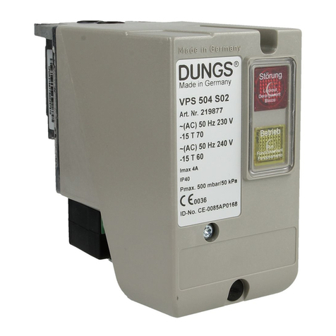
Dungs VPS 504 Service manual

Dungs

Dungs VPS 504 Service manual

Dungs GasMultiBloc MB-D B07 Series User manual

Dungs

Dungs GasMultiBloc MB-D B07 Series User manual

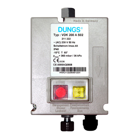
Dungs VDK 200 Service manual

Dungs

Dungs VDK 200 Service manual

Dungs FRSBV 20010 Series User manual

Dungs

Dungs FRSBV 20010 Series User manual

Dungs GasMultiBloc MB-VEF B01 User manual

Dungs

Dungs GasMultiBloc MB-VEF B01 User manual

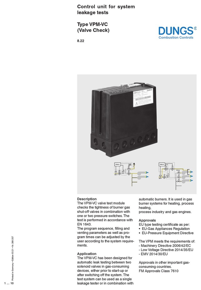
Dungs VPM-VC User manual

Dungs

Dungs VPM-VC User manual

Dungs DMV-D(LE) 704/6x4 Series User manual

Dungs

Dungs DMV-D(LE) 704/6x4 Series User manual

Dungs DGAI. 20/5 Product guide

Dungs

Dungs DGAI. 20/5 Product guide

Dungs DSLC px Vx Service manual

Dungs

Dungs DSLC px Vx Service manual

Dungs VPM-LC User manual

Dungs

Dungs VPM-LC User manual

Dungs MV X Product guide

Dungs

Dungs MV X Product guide

Dungs SV-DLE 1005/604 Service manual

Dungs

Dungs SV-DLE 1005/604 Service manual

Dungs DMV 11 eco Series Service manual

Dungs

Dungs DMV 11 eco Series Service manual

Dungs GasMultiBloc MBC-65 Series User manual

Dungs

Dungs GasMultiBloc MBC-65 Series User manual

Dungs DMV Series User manual

Dungs

Dungs DMV Series User manual

Dungs VPM-VC Service manual

Dungs

Dungs VPM-VC Service manual

Dungs MultiBloc MBE-S Series User manual

Dungs

Dungs MultiBloc MBE-S Series User manual

Dungs SAV 100065 User manual

Dungs

Dungs SAV 100065 User manual

Dungs VPM-VC User manual

Dungs

Dungs VPM-VC User manual

Dungs DGAI. 33F/2 Service manual

Dungs

Dungs DGAI. 33F/2 Service manual

Popular Control Unit manuals by other brands

Radionics D208RF installation instructions

Radionics

Radionics D208RF installation instructions

Toshiba TCB-CC163TLE installation manual

Toshiba

Toshiba TCB-CC163TLE installation manual

FabiaTech FB2410 Series User's quick setting

FabiaTech

FabiaTech FB2410 Series User's quick setting

FNW 1000 WOG Installation, operation & maintenance instructions

FNW

FNW 1000 WOG Installation, operation & maintenance instructions

Aideepen SWM-103 instruction manual

Aideepen

Aideepen SWM-103 instruction manual

APARIAN A-TSM user manual

APARIAN

APARIAN A-TSM user manual

LiteOn WCBN3510A user manual

LiteOn

LiteOn WCBN3510A user manual

Comelit 8273 Technical manual

Comelit

Comelit 8273 Technical manual

adept technology R Series Instruction handbook

adept technology

adept technology R Series Instruction handbook

Eaton SL7 Series Instruction leaflet

Eaton

Eaton SL7 Series Instruction leaflet

Bosch B901 installation guide

Bosch

Bosch B901 installation guide

PARCOL 1-6940 Series instruction manual

PARCOL

PARCOL 1-6940 Series instruction manual

HBM TEDS operating manual

HBM

HBM TEDS operating manual

Trane XL824 user guide

Trane

Trane XL824 user guide

Eaton Cutler-Hammer Durant PRESIDENT Series Installation and operation manual

Eaton

Eaton Cutler-Hammer Durant PRESIDENT Series Installation and operation manual

HomeMatic HMW-Sen-SC-12-FM Installation and operating manual

HomeMatic

HomeMatic HMW-Sen-SC-12-FM Installation and operating manual

Bola E 680-21 operating instructions

Bola

Bola E 680-21 operating instructions

Lippert Ground Control 3.0 LCD manual

Lippert

Lippert Ground Control 3.0 LCD manual

manuals.online logo
manuals.online logoBrands
  • About & Mission
  • Contact us
  • Privacy Policy
  • Terms and Conditions

Copyright 2025 Manuals.Online. All Rights Reserved.