manuals.online logo
Brands
  1. Home
  2. •
  3. Brands
  4. •
  5. Tyco Electronics
  6. •
  7. Crimping Tools
  8. •
  9. Tyco Electronics PRO-CRIMPER III User manual

Tyco Electronics PRO-CRIMPER III User manual

Instruction Sheet
PRO-CRIMPER* III Hand
Tool Assembly 224928-1 408-4167
L C B
1
of 4
E
2008 Tyco Electronics Corporation, Harrisburg, PA
All International Rights Reserved
TE logo and Tyco Electronics are trademarks.
*Trademark. ther products, logos, and company names used are the property of their respective owners.
T LING ASSISTANCE CENTER 1-800-722-1111
PR DUCT INF RMATI N1-800-522-6752 This controlled document is subject to change.
For latest revision and Regional Customer Service,
visit our website at
www.tycoelectronics.com
24 JAN 08 Rev A
with Die Assembly 224928-2
PROPER SE G IDELINES
CumulativeTraumaDisorderscanresultfromtheprolongeduseof manuallypoweredhandtools.Handtoolsareintendedforoccasionaluseandlowvolume
applications. A wide selection of powered application equipment for extended-use, production operations is available.
Figure 1
}
Contact the Tooling Assistance Center
(see below) for specific connector part numbers.
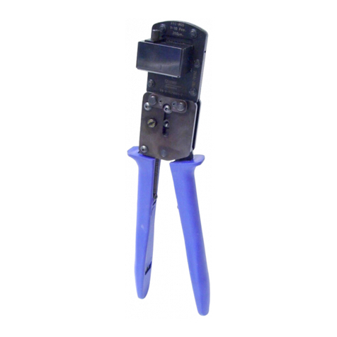
The PR -CRIMPER III Hand Tool is a Commercial" grade tool and is
designed primarily for field installation, repair, maintenance work, or
prototyping in industrial, commercial, or institutional applications. Product
crimped with this tool will meet the crimp height requirement for hand tools in
the appropriate 114 application specification, but may not comply with other
feature parameters of the specification. Tyco Electronics offers a variety of
tools to satisfy your performance requirements. For additional information,
contact the Tooling Assistance Center at 1-800-722-1111.
Ratchet
Adjustment Wheel
PR -CRIMPER III
Hand Tool Frame
354940-1
Stationary
Handle
Moving
Handle
Pivot
Pin
Back of Tool
Stationary
Jaw
Die Assembly
224928-2
Moving Jaw
DIE ASSEMBLY
PART N MBER CONNECTOR
FAMILY
}
TYPE
CABLE
INS L DIA
(mm [in.])
224928-2 Modular Plug Connectors
(External Strain Relief Application) Stranded or Solid,
Unshielded or Shielded Round Jacket 4.70-5.46
[.185-.215]
1. INTROD CTION
PRO–CRIMPER III Hand Tool Assembly 224928–1
consists of Die Assembly 224928–2 and
PRO–CRIMPER III Hand Tool Frame 354940–1. The
die assembly consists of two crimping dies. Read
these instructions thoroughly before crimping any
connectors.
Dimensions on this sheet are in millimeters [with
inch equivalents provided in brackets]. Figures
and illustrations are for identification only and are
not drawn to scale.
Reason for revision is provided in Section 9,
REVISION SUMMARY.
2. DESCRIPTION
(Figures 1 and 2)
The tool features a tool frame with a stationary jaw
and handle, a moving jaw, a moving handle, and an
adjustable ratchet that ensures external strain relief
crimping. The tool frame holds a die assembly with a
seating chamber and two crimping chambers.
The die assembly features an indenter die and an
anvil die.
Die retaining pins and die retaining screws are used
to position and secure the dies in the tool frame.
NOTE
i
408-4167
PRO-CRIMPER III Hand Tool Assembly 224928-1 with Die Assembly 224928-2
Rev
A2
of 4 Tyco Elect onics Co po ation
Figure 2
Anvil
Die
Chamfe
Die Retaining
Sc ews
Die Retaining
Pins
Tool F ame
Indente
Die
Wi e Insulation
Diamete Ma kings
3. INSTALLATION AND REMOVAL OF
DIE ASSEMBL
(Figu e 2)
1. Open the tool handles and remove the two die
retaining screws from the tool jaws.
2. Place the anvil die so that the chamfered side
faces outward when mounted in the moving jaw of
the tool frame.
3. Insert the two die retaining pins.
4. Insert the die retaining screw through the jaw
and through the anvil die, and tighten the screw
just enough to hold the die in place. Do
not
tighten
the screw completely at this time.
5. Observe the wire insulation diameter markings
on the indenter die. Place the indenter die so that
the crimping chamber to be used is facing outward
when mounted in the stationary jaw of the tool
frame.
6. Insert the two die retaining pins.
7. Insert the die retaining screw through the jaw
and the indenter die, and tighten the screw just
enough to hold the die in place. Do
not
tighten the
screw completely at this time.
8. Carefully close the tool handles, making sure
that the anvil and indenter align properly. Continue
closing the tool handles until the ratchet in the tool
frame has engaged sufficiently to hold the anvil
and indenter in place, then tighten both die
retaining screws.
9. To disassemble, close the tool handles until the
ratchet releases, remove the two die retaining
screws, and the four die retaining pins, and slide
the anvil and indenter out of the tool jaws.
4. CRIMPING PROCEDURE
Assemble the modular plug connector according to
Application Specification 114–6016. Insert the
external strain relief into the modular plug as shown in
Figure 3, Detail A, and proceed as follows:
1. Squeeze tool handles together and allow them
to open fully.
2. Position the modular plug assembly in the
seating chamber on the anvil die as shown in
Figure 3, Detail B. Make sure that the external
strain relief faces the indenter die and that the
support barrel does not enter the seating chamber.
3. Hold the modular plug assembly in position and
squeeze the tool handles together until ratchet
releases. Allow tool handles to open and remove
the modular jack assembly.
4. Position the modular plug assembly in the
crimping chamber on the anvil die so that the
opening in the external strain relief support barrel
faces the indenter die. Make sure the back of the
modular plug butts against the edge of the die. See
Figure 3, Detail C.
408-4167
PRO-CRIMPER III Hand Tool Asse bly 224928-1 with Die Asse bly 224928-2
3
of 4Rev
A
Tyco Electronics Cor oration
Make sure that both sides of the support barrel
are started evenly into the crimping chamber. Do
NOT attempt to crimp an improperly positioned
modular plug assembly.
5. Holding the modular plug assembly in place,
squeeze tool handles together until ratchet
releases. Allow tool handles to open and remove
crimped modular plug assembly.
6. Check the external strain relief for a proper
crimp as shown in Figure 4. If necessary, adjust
the crimp height as described in Section 5, CRIMP
HEIGHT ADJUSTMENT.
Figure 3
Insert External
Strain Relief into
Modular Plug
Su ort Barrel in Crim ing
Chamber on Anvil Die with
O ening in Su ort Barrel
Facing Indenter Die
Su ort
Barrel
External Strain Relief
Faces Indenter Die
Back of Modular
Plug Butts Against
Edge of Die
Detail A
Detail B
Detail C
Figure 4
Acceptable Unacceptable
External Strain Relief Must Be
Seated Flat Against Modular Plug
Su ort Barrel Must
Be Evenly Crim ed
and Firm Around Cable
Su ort Barrel
Crim Too Loose
Su ort Barrel Crim Uneven
and Cuts into Cable
CAUTION
!
408-4167
PRO-CRIMPER III H nd Tool Assembly 224928-1 with Die Assembly 224928-2
Rev
A4
of 4 Tyco Electron cs Corporat on
5. CRIMP NEST
The crimp nest may be removed and rotated 180°to
accommodate two sizes of insulation. Dimensions for
these wire insulation sizes are shown in Figure 5.
Figure 5
For 4.70-5.08 mm [.185-.200 in.] Insulation Dia.
For 5.08-5.46 mm [.200-.215 in.] Insulation Dia.
8.43 +0.15
[.332 +.006]
8.43 +0.15
[.332 +.006]
5.33 +0.10
[.210 +.004]
6.10 +0.10
[.240 +.004]
.185-.200
.200-.215
6. CRIMP HEIGHT ADJUSTMENT
(F gure 6)
1. Remove the lockscrew from the ratchet
adjustment wheel.
2. With a screwdriver, adjust the ratchet wheel
from the back of the tool.
3. Observe the ratchet adjustment wheel. If a
tighter crimp is required, rotate the adjustment
wheel COUNTERCLOCKWISE to a
higher–numbered setting. If a looser crimp is
required, rotate the adjustment wheel
CLOCKWISE to a lower–numbered setting.
4. Replace the lockscrew.
5. Make a sample crimp and visually check the
crimp height (refer to Figure 4). If the crimp is
acceptable, replace and secure the lockscrew. If
the crimp is unacceptable, continue to adjust the
ratchet, and again measure a sample crimp.
7. MAINTENANCE
Ensure that the tool and dies are clean by wiping
them with a clean, soft cloth. Remove any debris with
a clean, soft brush. Do not use objects that could
damage the tool. When not in use, keep handles
closed to prevent objects from becoming lodged in
the crimping dies, and store in a clean, dry area.
8. VISUAL INSPECTION
The crimping dies should be inspected on a regular
basis to ensure that they have not become worn or
damaged. Inspect the crimping chambers for
flattened, chipped, worn, or broken areas. If damage
or abnormal wear is evident, the tool must be
replaced. See Section 9, REPLACEMENT.
Figure 6
Screwdr ver
Ratchet
Adjustment
Wheel
Lockscrew
(Typ)
9. REPLACEMENT
Customer–replaceable parts are shown in Figure 1. If
the dies are damaged or worn excessively, they must
be replaced. Order replaceable parts through your
Tyco Electronics Representative, or call
1–800–526–5142, or send a facsimile of your
purchase order to 1–717–986–7605, or write to:
CUSTOMER SERVICE (38–35)
TYCO ELECTRONICS CORPORATION
P.O. BOX 3608
HARRISBURG, PA 17105–3608
10. REVISION SUMMARY
S
Updated document to corporate requirements
S
Added new Section 5, and renumbered
S
Added new Figure 5 and renumbered

This manual suits for next models

2

Other Tyco Electronics Crimping Tools manuals
Tyco Electronics 58591-1 User manual

Tyco Electronics

Tyco Electronics 58591-1 User manual

Tyco Electronics 58425 Series User manual

Tyco Electronics

Tyco Electronics 58425 Series User manual

Tyco Electronics ERGOCRIMP 6-1579001-5 User manual

Tyco Electronics

Tyco Electronics ERGOCRIMP 6-1579001-5 User manual

Tyco Electronics PRO- CRIMPER III User manual

Tyco Electronics

Tyco Electronics PRO- CRIMPER III User manual

Tyco Electronics PRO-CRIMPER III User manual

Tyco Electronics

Tyco Electronics PRO-CRIMPER III User manual

Tyco Electronics SDE PEW-12 User manual

Tyco Electronics

Tyco Electronics SDE PEW-12 User manual

Tyco Electronics 1490748-1 User manual

Tyco Electronics

Tyco Electronics 1490748-1 User manual

Tyco Electronics PRO-CRIMPER III User manual

Tyco Electronics

Tyco Electronics PRO-CRIMPER III User manual

Tyco Electronics PRO-CRIMPER III User manual

Tyco Electronics

Tyco Electronics PRO-CRIMPER III User manual

Tyco Electronics 45449 User manual

Tyco Electronics

Tyco Electronics 45449 User manual

Tyco Electronics PRO-CRIMPER III User manual

Tyco Electronics

Tyco Electronics PRO-CRIMPER III User manual

Tyco Electronics PRO-CRIMPER III User manual

Tyco Electronics

Tyco Electronics PRO-CRIMPER III User manual

Tyco Electronics 2063811-1 User manual

Tyco Electronics

Tyco Electronics 2063811-1 User manual

Tyco Electronics 1752787-1 User manual

Tyco Electronics

Tyco Electronics 1752787-1 User manual

Tyco Electronics PRO-CRIMPER III User manual

Tyco Electronics

Tyco Electronics PRO-CRIMPER III User manual

Tyco Electronics 58605-1 User manual

Tyco Electronics

Tyco Electronics 58605-1 User manual

Tyco Electronics 696675-1 User manual

Tyco Electronics

Tyco Electronics 696675-1 User manual

Tyco Electronics 603995 Series User manual
Tyco Electronics

Tyco Electronics 603995 Series User manual

Tyco Electronics PRO- CRIMPER III User manual

Tyco Electronics

Tyco Electronics PRO- CRIMPER III User manual

Tyco Electronics ERGOCRIMP 2-1579021-9 User manual

Tyco Electronics

Tyco Electronics ERGOCRIMP 2-1579021-9 User manual

Tyco Electronics 1804834-1 User manual

Tyco Electronics

Tyco Electronics 1804834-1 User manual

Tyco Electronics DYNA-CRIMP 69065 User manual

Tyco Electronics

Tyco Electronics DYNA-CRIMP 69065 User manual

Tyco Electronics DYNA-CRIMP User manual

Tyco Electronics

Tyco Electronics DYNA-CRIMP User manual

Tyco Electronics 1901820-1 User manual

Tyco Electronics

Tyco Electronics 1901820-1 User manual

Popular Crimping Tools manuals by other brands

molex 63811-8100 Specification sheet

molex

molex 63811-8100 Specification sheet

Klauke TEXTRON K05 instruction manual

Klauke

Klauke TEXTRON K05 instruction manual

VETEC SPM32-18 instruction manual

VETEC

VETEC SPM32-18 instruction manual

molex 63825-1670 Specification sheet

molex

molex 63825-1670 Specification sheet

Panduit CTFP-100 operating instructions

Panduit

Panduit CTFP-100 operating instructions

molex 63819-3700 manual

molex

molex 63819-3700 manual

Staubli PV-CZM Operating	 instruction

Staubli

Staubli PV-CZM Operating instruction

Ilsco TASKMASTER TB-6DF1000-P instruction manual

Ilsco

Ilsco TASKMASTER TB-6DF1000-P instruction manual

molex 207129 Series Specification sheet
molex

molex 207129 Series Specification sheet

molex 11-01-0185 Specification sheet

molex

molex 11-01-0185 Specification sheet

Lapp Group EPIC CIRCON  LS1/M23 instruction manual

Lapp Group

Lapp Group EPIC CIRCON LS1/M23 instruction manual

TE SDE PEW 12 instruction sheet

TE

TE SDE PEW 12 instruction sheet

Klauke ESSGL instruction manual

Klauke

Klauke ESSGL instruction manual

HSS Hire 68613 Operating & safety guide

HSS Hire

HSS Hire 68613 Operating & safety guide

TOOLCRAFT 2368331 operating instructions

TOOLCRAFT

TOOLCRAFT 2368331 operating instructions

Emerson Klauke EK120 Series manual

Emerson

Emerson Klauke EK120 Series manual

Textron Greenlee Gator E12CCXLT Operation manual

Textron

Textron Greenlee Gator E12CCXLT Operation manual

Santec BNC-HD-CCTV-KIT Quick installation guide

Santec

Santec BNC-HD-CCTV-KIT Quick installation guide

manuals.online logo
manuals.online logoBrands
  • About & Mission
  • Contact us
  • Privacy Policy
  • Terms and Conditions

Copyright 2025 Manuals.Online. All Rights Reserved.