manuals.online logo
Brands
  1. Home
  2. •
  3. Brands
  4. •
  5. Tyco Electronics
  6. •
  7. Crimping Tools
  8. •
  9. Tyco Electronics 1901820-1 User manual

Tyco Electronics 1901820-1 User manual

Instruction Sheet
408-10111
LOC B
1
of 4
E
2007 Tyco Electronics Corporation, Harrisburg, PA
All International Rights Reserved
TE logo and Tyco Electronics are trademarks.
*Trademark. Other products, logos, and company names used are the property of their respective owners.
TOOLING ASSISTANCE CENTER 1-800-722-1111
PROD CT INFORMATION 1-800-522-6752 This controlled document is subject to change.
For latest revision and Regional Customer Service,
visit our website at
www.tycoelectro ics.com
30 OCT 07 Rev B
Hydraulic Crimpi g Head 1901820-1
MPORTANT SAFETY INFORMATION
408-10111
Hydr ulic Crimping He d 1901820-1
Rev
B2
of 4 yco Electronics Corporation
Figure 1
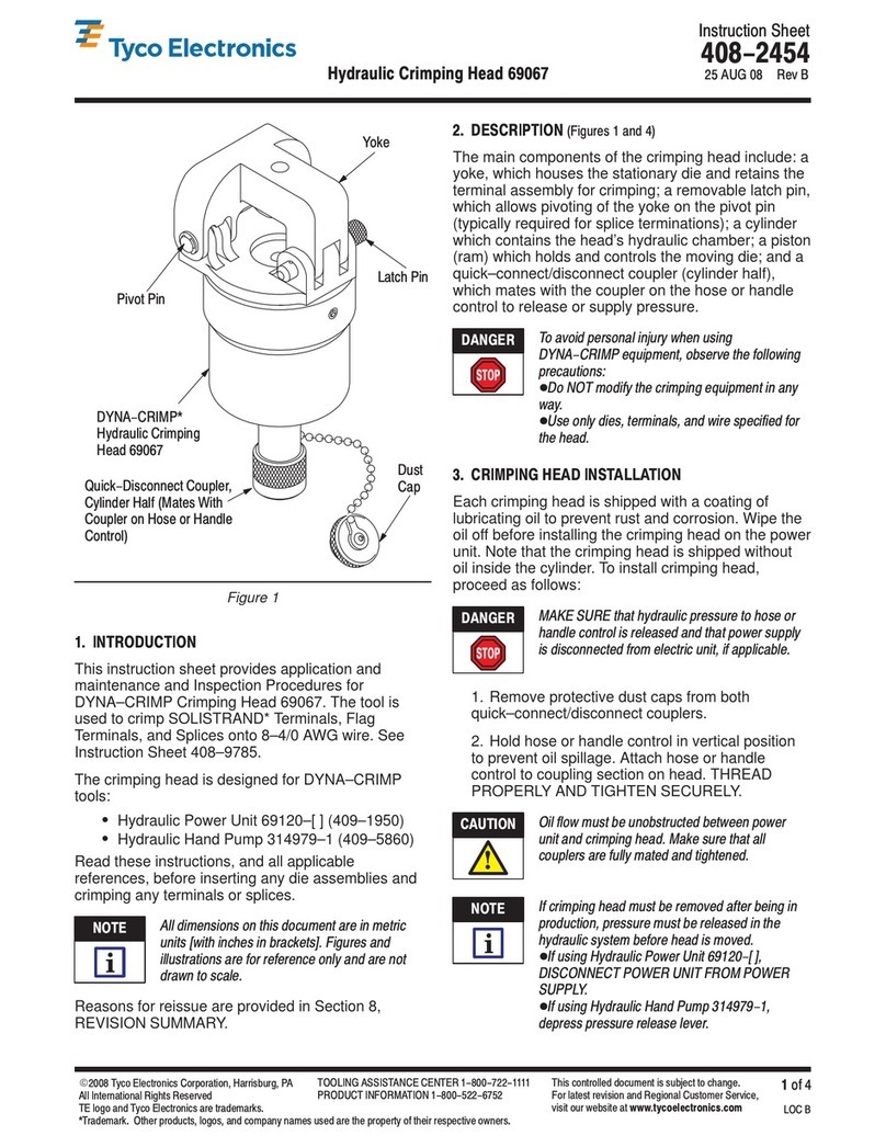
Upper Die
Release
Button
Die Retaining
Pins
Ram
(Advanced)
Quick-Disconnect
Coupling Dust Cap
Cylinder
Lower Die Release
Button
C"-Head
1. INTRODUCTION
This instruction sheet provides operation and
maintenance instructions for the 12 Ton Hydraulic
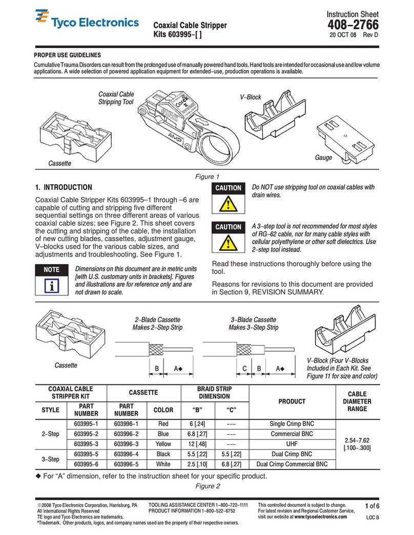
Crimping Head 1901820–1. See Figure 1.
The crimping head is designed to use dies that crimp
the terminals in Figure 2. Figure 2 also lists the wire
sizes onto which the terminals and splices are
crimped, as well as the instruction sheet for the
crimping dies.
TERMINALS WIRE SIZE
(AWG) INSTRUCTION
SHEET
AMPOWER*
erminals and Splices 6 hrough 3/0 408-8703
SOLIS RAND*
erminals and Splices 8 hrough 4/0 408-8691
ERMINYL*
erminals and Splices 8 hrough 4 408-8704
Figure 2
Dimensions on this document are in metric units
[with U. S. customary units in brackets], unless
otherwise specified.
2. DESCRIPTION
(Figure 1)
Main components of Hydraulic Crimping Head
1901820–1 include a “C”–head, which houses the
stationary die, the upper and lower die release
buttons which release the dies, a cylinder which
contains the head’s hydraulic chamber, a piston (ram)
which holds and controls the moving die, and a
quick–disconnect coupling (cylinder half) which mates
with the coupling on the hose to release or supply
pressure. A dust cap covers the quick–disconnect
coupling.
3. INSTALLATION
3.1. He d Inst ll tion
Prior to installing the head, ensure that the pump
and hose being used are working properly, and
are adjusted to and rated at 10,000 psi. An
incorrectly adjusted or rated pump/hose could
result in severe tooling damage, as well as
personal injury.
1. Release the hydraulic pressure to the hose.
Disconnect electric power unit from power supply.
2. Remove protective dust caps.
3. Thoroughly clean the coupling on the
pump/hose and the coupling on the crimping head.
4. Mate both quick–disconnect couplings and
tighten the collar of the coupler assembly on the
hose.
Oil flow must be unobstructed between the power
unit and the crimping head. Ensure that all
couplings are fully mated and tightened.
If a crimping head must be removed after the
power unit was in operation, be sure to release
the pressure in the hydraulic system. When
using Hydraulic Power Unit 1804700-[ ],
DISCONNECT THE POWER UNIT FROM THE
POWER SUPPL . When using Hydraulic Foot
Pump 1583659-1 or Hydraulic Hand Tool
1583661-1, depress the pressure release pedal
to release pressure.
3.2. Die Inst ll tion
To avoid personal injury, do NOT accidentally
depress the footswitch or handle control when
installing or removing dies.
NOTE
i
CAUTION
!
CAUTION
!
NOTE
i
DANGER
408-10111
Hydraulic Crimping Head 1901820-1
3
of 4Rev
B
Tyco Electronics Corporation
Operating the head WITHOUT the crimping dies
installed will damage the C"-Head or ram.
Install the dies as described in the appropriate die
instruction sheet. Refer to Figure 2.
4. CRIMPING PROCEDURE
The following procedure provides only general
information concerning crimping. Refer to the
instructions packaged with the dies (see
Figure 2) and power unit for detailed information,
including wire stripping dimensions and instructions
for positioning terminals and splices in the dies.
1. Insert terminal or splice in the stationary die
according to the instructions packaged with the
dies.
2. Activate the power unit to advance the dies and
hold the terminal or splice in place.
3. Insert stripped wire into the terminal or splice.
4. Activate the power unit to complete the crimp.
5. INSPECTION/MAINTENANCE
Make s re hydra lic press re is released and
power s pply is disconnected before following
inspection and maintenance proced res, nless
otherwise specified in the proced re.
Each crimping head is assembled and inspected
before shipment. It is recommended that the crimping
head be inspected immediately upon its arrival at your
facility, and at regularly scheduled intervals, to ensure
that the crimping head has not been damaged during
handling. Frequency of inspection depends upon the
following:
S
Care, amount of use, and handling of the head;
S
Type and size of products crimped;
S
Degree of operator skill; and
S
Environmental conditions.
Once a year, or every 7,500 cycles (whichever comes
first), the hydraulic head should be returned to Tyco
Electronics for magnetic particle inspection.
Additionally, inspect and service the head (as
described in Figure 3) every month or 1,000 cycles,
whichever comes first. Refer to Figure 1.
5.1. Cleaning
Remove accumulations of dirt and grease on the
crimping head, especially in areas where dies are
installed and terminals are crimped. Clean the entire
head frequently with a clean, lint–free cloth.
5.2. Visual Inspection
In addition to the inspections listed in Figure 3,
inspect the head for nicks, scratches, and cracks.
Inspect for cracks especially at the corners of the
“C”–head and around the top of the cylinder. Refer to
Figure 4.
Inspect the metal surfaces for nicks, cracks,
scratches, and excessive wear, especially where
sliding contact occurs.
5.3. Crimping Head Check-Out Procedure
If the ram fails to retract after completion of a
crimping cycle, the cause may be in the crimping
head. To determine whether or not the trouble is in
the crimping head, release pressure in the power unit.
If the ram retracts, the trouble is not in the crimping
head. If ram does NOT retract, refer to Section 6,
RETURN/REPAIR.
6. RETURN/REPAIR
Order replacement parts through your Tyco
Electronics representative, or call 1–800–526–5142,
or send a facsimile of your purchase order to
1–717–986–7605, or write to:
CUSTOMER SERVICE (38–35)
TYCO ELECTRONICS CORPORATION
P.O. BOX 3608
HARRISBURG, PA 17105–3608
Crimping heads may also be returned for evaluation
and repair. For tool repair service, contact a Tyco
Electronics representative at 1–800–526–5136.
7. REVISION SUMMAR
Since the previous release of this document, the
corporate logo was updated.
CAUTION
!
DANGER
408-10111
Hydraulic Cri ping Head 1901820-1
Rev
B4
of 4 Tyco Electronics Corpor tion
ITEM TO BE
INSPECTED INSPECTION/PROBLEM POSSIBLE SOLUTION
Inspect for cr cks, gouges, nicks, or g lling on the
C"-He d or where the C"-He d cont cts dies. Return tool for rep ir (see Section 6,
RETURN/REPAIR).
C"-He d Check to see if the upper die ret ining pin does not
hold the st tion ry die in pl ce. Return tool for rep ir (see Section 6,
RETURN/REPAIR).
Check to see if the upper die rele se button sticks
(it should norm lly move in nd out e sily when
moder te pressure is pplied).
Return tool for rep ir (see Section 6,
RETURN/REPAIR).
Ins
p
ect for evidence of cr cks,
g
ou
g
es, nicks, or
If there re cr cks, return the tool for rep ir (see
Section 6, RETURN/REPAIR).
p,gg,,
g lling. For tr ces of gouges, nicks, or g lling: Remove ny
sh rp edges using fine emery cloth.
Cylinder Inspect for oil le ks between the cylinder nd
coupling.
For oil le ks nd sticky coupling tighten or repl ce
Check to see if the coupling sticks to the cylinder (it
should norm lly turn on nd off freely when moder te
pressure is pplied with pplied with wrench).
F
or o
il l
e
k
s n
d
s
ti
c
k
y coup
li
ng,
ti
g
ht
en or rep
l
ce
the coupling
Quick-Disconnect
Coupling The coupling m tes h rd or won't m te or rele se, or
it le ks oil, or it sticks t the hose connection. Repl ce coupling.
Inspect the r m in the Power ON" (r m dv nced)
position for evidence of g lling, cr cks, or oil le ks
bt th dth lid
If there re cr cks or le ks, return the tool for rep ir
(see Section 6, RETURN/REPAIR).
between the r m nd the cylinder. If there is g lling, remove ny sh rp edges using
fine emery cloth.
R m
Check to see if the lower die ret ining pin does not
hold the moving die in pl ce. Return tool for rep ir (see Section 6,
RETURN/REPAIR).
R m
Check to see if the lower die rele se button sticks
(it should norm lly move in nd out e sily when
moder te pressure is pplied).
Return tool for rep ir (see Section 6,
RETURN/REPAIRS).
Inspect the r m in the Power OFF" (r m retr cted)
position to ensure th t the r m returns freely to its
origin l position.
Return tool for rep ir (see Section 6,
RETURN/REPAIRS).
Figure 3
Figure 4
Check These
Areas for Cracks
Quick-Disconnect
Coupling 311470-1

Other Tyco Electronics Crimping Tools manuals
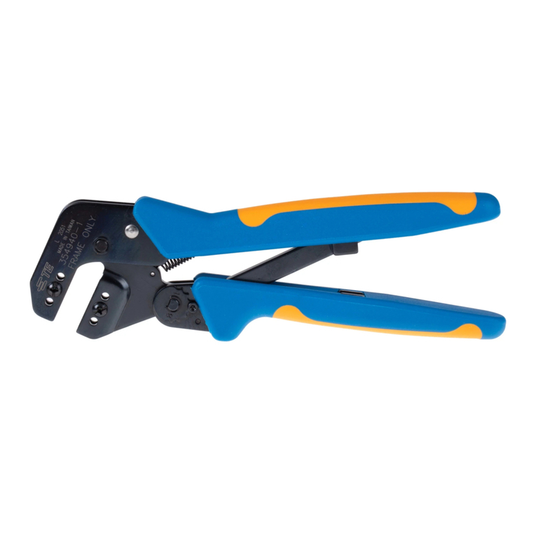
Tyco Electronics PRO-CRIMPER III User manual

Tyco Electronics

Tyco Electronics PRO-CRIMPER III User manual
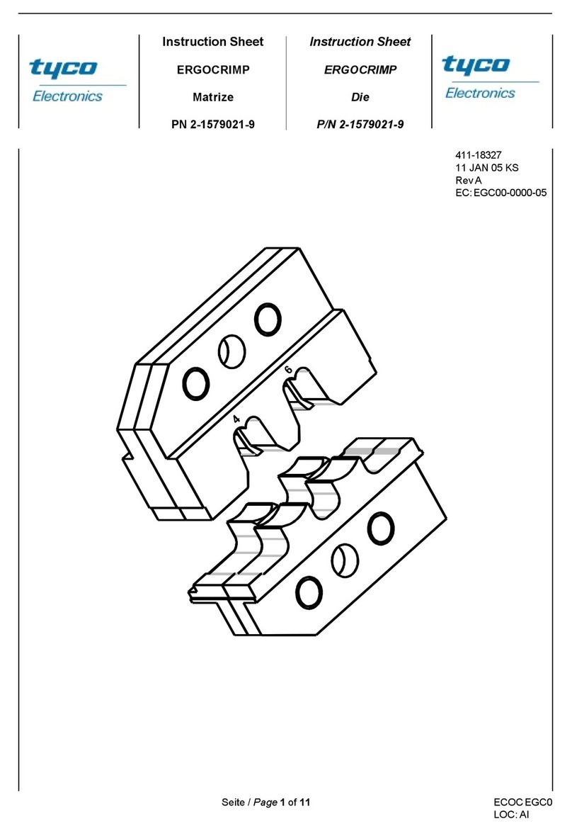
Tyco Electronics 1213850-1 User manual

Tyco Electronics

Tyco Electronics 1213850-1 User manual

Tyco Electronics 90035-3 User manual

Tyco Electronics

Tyco Electronics 90035-3 User manual

Tyco Electronics 46121 User manual

Tyco Electronics

Tyco Electronics 46121 User manual

Tyco Electronics PRO-CRIMPER III User manual

Tyco Electronics

Tyco Electronics PRO-CRIMPER III User manual

Tyco Electronics 58605-1 User manual

Tyco Electronics

Tyco Electronics 58605-1 User manual

Tyco Electronics PRO-CRIMPER III User manual

Tyco Electronics

Tyco Electronics PRO-CRIMPER III User manual

Tyco Electronics 58443-1 User manual

Tyco Electronics

Tyco Electronics 58443-1 User manual

Tyco Electronics PRO-CRIMPER III User manual

Tyco Electronics

Tyco Electronics PRO-CRIMPER III User manual

Tyco Electronics PRO-CRIMPER II User manual

Tyco Electronics

Tyco Electronics PRO-CRIMPER II User manual

Tyco Electronics 58569-1 User manual

Tyco Electronics

Tyco Electronics 58569-1 User manual

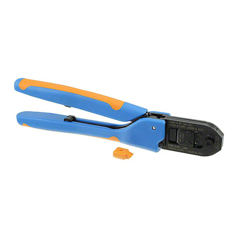
Tyco Electronics ERGOCRIMP 2-1579021-9 User manual
Tyco Electronics

Tyco Electronics ERGOCRIMP 2-1579021-9 User manual

Tyco Electronics 58649-1 User manual

Tyco Electronics

Tyco Electronics 58649-1 User manual

Tyco Electronics 603995 Series User manual

Tyco Electronics

Tyco Electronics 603995 Series User manual

Tyco Electronics ROTA-CRIMP 68321-1 User manual

Tyco Electronics

Tyco Electronics ROTA-CRIMP 68321-1 User manual

Tyco Electronics PRO-CRIMPER III User manual

Tyco Electronics

Tyco Electronics PRO-CRIMPER III User manual

Tyco Electronics 90654-1 User manual

Tyco Electronics

Tyco Electronics 90654-1 User manual

Tyco Electronics PRO-CRIMPER III User manual

Tyco Electronics

Tyco Electronics PRO-CRIMPER III User manual

Tyco Electronics 1804834-1 User manual

Tyco Electronics

Tyco Electronics 1804834-1 User manual

Tyco Electronics PRO-CRIMPER III User manual

Tyco Electronics

Tyco Electronics PRO-CRIMPER III User manual

Tyco Electronics 48858-1 User manual

Tyco Electronics

Tyco Electronics 48858-1 User manual

Tyco Electronics 58425 Series User manual

Tyco Electronics

Tyco Electronics 58425 Series User manual

Tyco Electronics 2063811-1 User manual

Tyco Electronics

Tyco Electronics 2063811-1 User manual

Tyco Electronics 90301-2 User manual

Tyco Electronics

Tyco Electronics 90301-2 User manual
Popular Crimping Tools manuals by other brands

JST CS 10-WC-SF1002 instruction manual

JST

JST CS 10-WC-SF1002 instruction manual

molex 63811-6170 Specification sheet

molex

molex 63811-6170 Specification sheet

Parker Parkrimp 2 - 83CE-083U instruction manual

Parker

Parker Parkrimp 2 - 83CE-083U instruction manual

BEX ProBEX PBO instruction sheet

BEX

BEX ProBEX PBO instruction sheet

molex 63823-7570 Specification sheet

molex

molex 63823-7570 Specification sheet

Fohrenbach HT119 user guide

Fohrenbach

Fohrenbach HT119 user guide

TE Connectivity SDE-SA instruction sheet

TE Connectivity

TE Connectivity SDE-SA instruction sheet

molex 207129 Series Specification sheet
molex

molex 207129 Series Specification sheet

molex 63811-5700 quick start guide

molex

molex 63811-5700 quick start guide

BARTON TOOLS EC300 instruction manual

BARTON TOOLS

BARTON TOOLS EC300 instruction manual

molex 64001-7300 Operating Instruction Sheet And Specifications

molex

molex 64001-7300 Operating Instruction Sheet And Specifications

molex 63825-7570 Specification sheet

molex

molex 63825-7570 Specification sheet

Staubli PV-CZM operating instructions

Staubli

Staubli PV-CZM operating instructions

Iwiss IWS-2612D Using instruction

Iwiss

Iwiss IWS-2612D Using instruction

molex 63825-9670 Specification sheet

molex

molex 63825-9670 Specification sheet

Harwin M22520/2-01 manual

Harwin

Harwin M22520/2-01 manual

molex 63827-3200 Specification sheet

molex

molex 63827-3200 Specification sheet

Emerson Klauke mini EK 15/50ML manual

Emerson

Emerson Klauke mini EK 15/50ML manual

manuals.online logo
manuals.online logoBrands
  • About & Mission
  • Contact us
  • Privacy Policy
  • Terms and Conditions

Copyright 2025 Manuals.Online. All Rights Reserved.