manuals.online logo
Brands
  1. Home
  2. •
  3. Brands
  4. •
  5. Tyco Electronics
  6. •
  7. Crimping Tools
  8. •
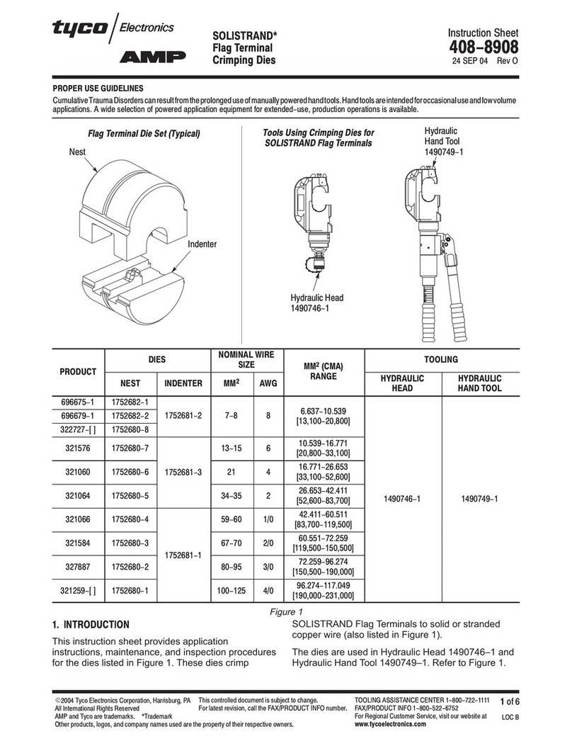
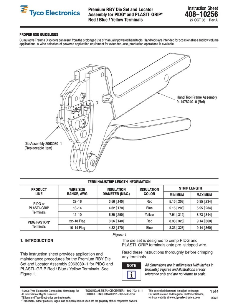
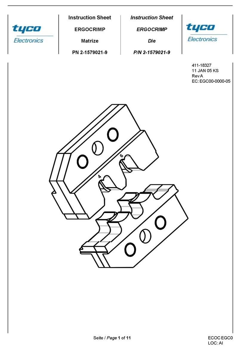
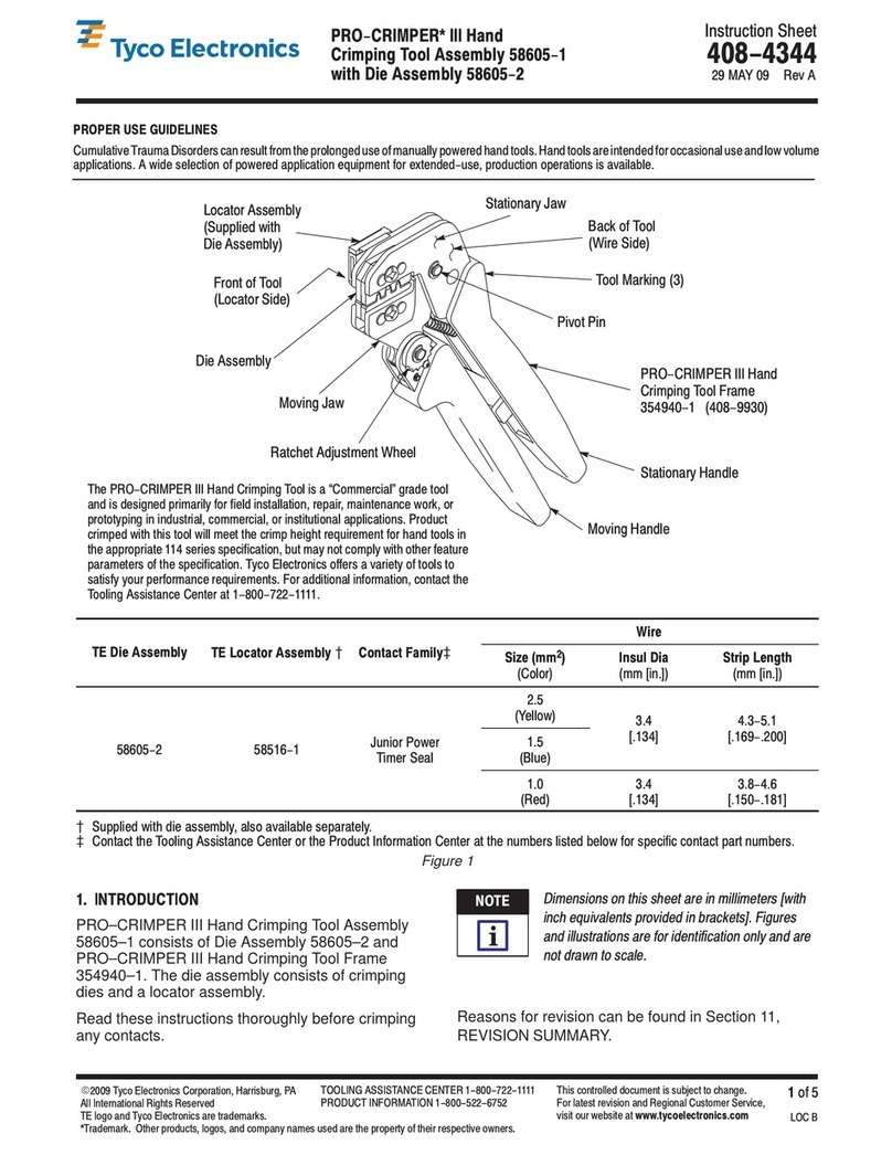
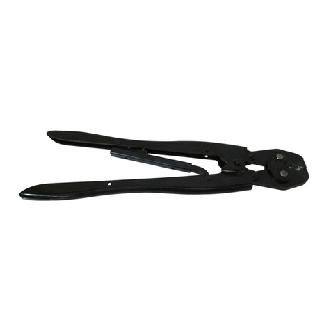
  9. Tyco Electronics PRO-CRIMPER III User manual

Tyco Electronics PRO-CRIMPER III User manual

Instruction Sheet
PRO-CRIMPER* III
Hand Tool Assembly 790163-[ ] 408-8738
LOC B
1
of 4
E
2007 Tyco Electronics Corporation, Harrisburg, PA
All International Rights Reserved
TE logo and Tyco Electronics are trademarks.
*Trademark. Other products, logos, and company names used are the property of their respective owners.
TOOLI G ASSISTA CE CE TER 1-800-722-1111
PRODUCT I FORMATIO 1-800-522-6752 This controlled document is subject to change.
For latest revision and Regional Customer Service,
visit our website at
www.tycoelectronics.com
31 JUL 07 Rev D
ith Die Assembly 790163-[ ]
PROPER USE GUIDELINES
CumulativeTraumaDisorderscanresultfromtheprolongeduse ofmanuallypoweredhandtools.Handtoolsareintendedforoccasionaluseandlowvolume
applications. A wide selection of powered application equipment for extended-use, production operations is available.
PRO-CRIMPER III hand tool is a Commercial" grade and is designed
primarily for field installation, repair, maintenance work, and prototyping in
industrial, commercial, and institutional applications. Product crimped with
this tool will meet the crimp height requirement for hand tools in the
appropriate application specification (114-series), but may not comply with
other feature parameters of the document. A variety of tools are offered to
satisfy performance requirements. For additional information, contact the
Tooling Assistance Center at the number at the bottom of this page.
Die Assembly
Moving
Jaw
Ratchet Adjustment
Wheel
Moving Handle
Stationary Handle
PRO-CRIMPER III Hand Tool
Frame 354940-1
Pivot Pin
Back of Tool
Stationary
Jaw
CABLE
HAND TOOL
ASSEMBLY DIE
ASSEMBLY MODULAR
PLUG
D
SIZE (A G) CONDUCTOR
INSULATION
DIAMETER (mm)
OUTSIDE
DIAMETER (mm) STRIP LENGTH
(mm)
790163-1 790163-2 336330-1, -2 5.0-6.0
790163-3 790163-4 336349-1 26-24 0.80-1.00 5.0-6.0
790163-5 790163-6 336462-1 6.0-7.0
35 0+5 0
1711413-1, -2 26-24 0.80-1.00
35
.
0
+
5
.
0
790163-7 790163-8 1933441-[ ] 26-24 0.89-1.09 4.7-5.3
1933442-[ ] 24-23 0.89-1.09
Figure 1
D
For additional modular plug part numbers, contact PRODUCT I FORMATIO at the bottom of this page.
1. INTRODUCTION
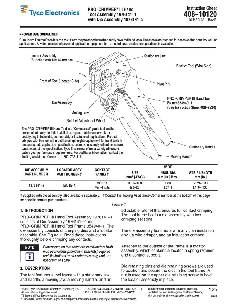
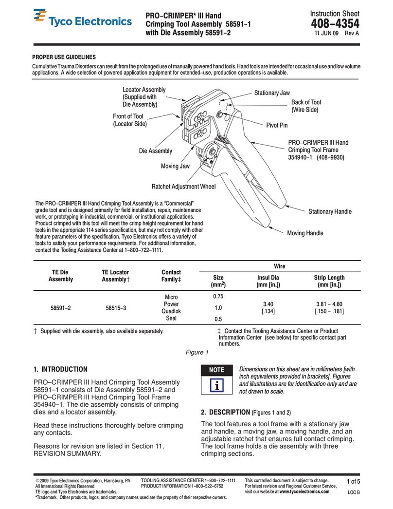
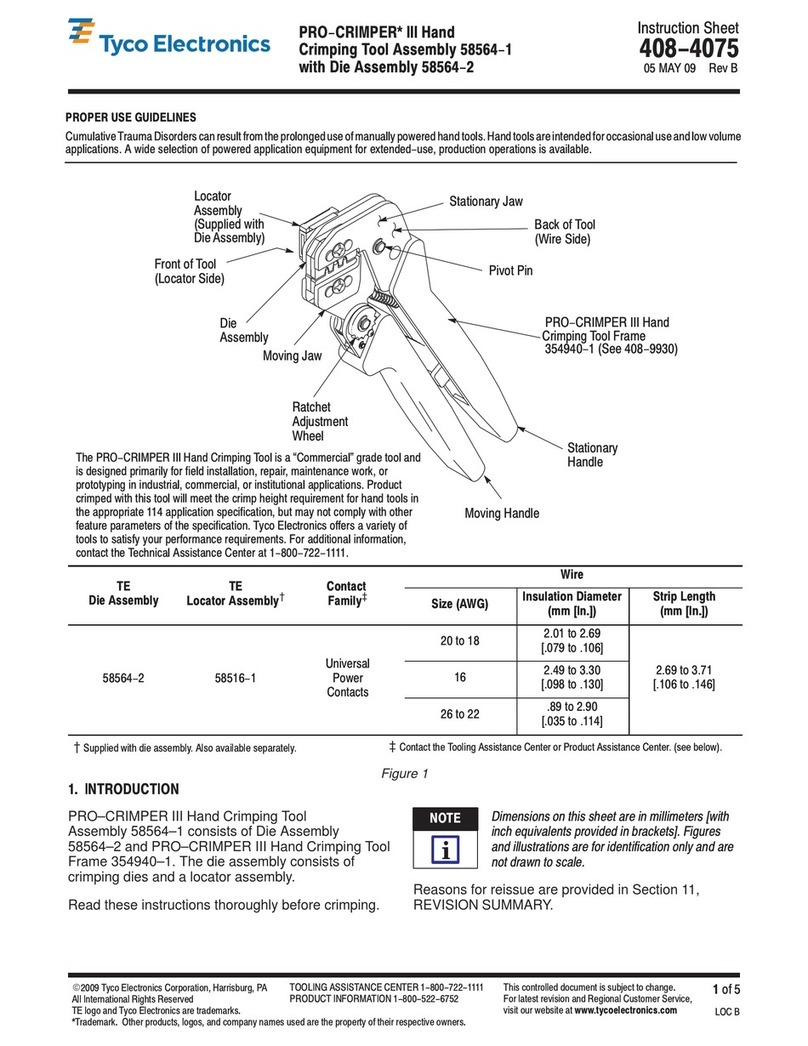
PRO–CRIMPER III Hand Tool Assembly 790163–[ ]
consists of PRO–CRIMPER III Hand Tool Frame
354940–1 and Die Assembly 790163–[ ].
The tool assembly is used to crimp the contacts, and
the internal and external strain reliefs of the modular
plugs listed in Figure 1.
Read these instructions thoroughly before using the
hand tool assembly.
Dimensions in this instruction sheet are in
millimeters. Figures are not drawn to scale.
Reasons for reissue of this instruction sheet are
provided in Section 8, REVISION SUMMARY.
NOTE
i
408-8738
PRO-CRIMPER III Hand Tool Assembly 1976319-1 with Die Assembly 1976320-1
Rev
D2
f4 Tyc Electr nics C rp rati n
2. DESCRIPTION
The tool frame features a stationary jaw and handle, a
moving jaw and handle, and an adjustable ratchet that
ensures full crimping. The tool frame holds the die
assembly. Refer to Figure 1.
The die assembly consists of an insulation stuffer,
wire stuffer, housing support, housing guides, and
mounting and retaining hardware.
3. INSTALLATION AND REMOVAL OF
DIE ASSEMBL
1. Close the tool handles until the ratchet releases,
then allow the handles to open fully. If present,
remove both retaining screws from the tool frame.
2. Orient the insulation stuffer as shown in Figure
2, and insert it into the stationary jaw of the tool
frame. Align the holes with the associated holes in
the tool frame. Insert the short retaining pins and
short retaining screw into the holes in the tool
frame. Tighten the screw.
3. Orient the housing support as shown in Figure
2, and insert it into the moving jaw of the tool
frame. Align the holes with the associated holes in
the tool frame. Orient the right housing guide as
shown, and mount it onto the tool frame using the
long retaining pins. Insert the long retaining screw
through the hole in the right housing guide. Tighten
the screw.
4. Refer to Figure 2. Orient the left housing guide
as shown, and secure it onto the tool frame using
the nut. Tighten the nut.
5. Carefully close the tool handles, making sure
that the parts align properly.
6. To disassemble, close the tool handles until the
ratchet releases. Remove the nut, screws, housing
guides, retaining pins, housing support, and
insulation stuffer out of the tool frame jaws.
4. CRIMPING PROCEDURE
Before proceeding, refer to the applicable Application
Specification: 114–22008 (Category 5e EMT) or
114–13035 and 114–93006 (Category 6 shielded),
and ensure the following:
— the modular plug and cable are compatible
— the cable polarity is properly maintained
— the modular plug is properly crimped and
assembled
Make sure that the modular plug shield is full
bottomed onto the bod . With some cables
containing
shielded twisted pairs
, this is
especiall IMPORTANT to check.
1. Close the tool handles until the ratchet releases,
then allow the handles to open FULLY.
2. Hold the tool so that the back is facing you.
Insert the modular plug (including shield and cable)
in the crimping chamber until it
bottoms
. Refer to
Figure 3.
Figure 2
Insulati n
Stuffer
Right H using
Guide
Sh rt Retaining
Screw
L ng Retaining
Screw
Sh rt Retaining
Pin (2 Places)
L ng Retaining
Pin (2 Places)
H using
Supp rt
Nut
Left H using
Guide
T l Frame
Wire Stuffer (Ref)
S cket Head Cap Screw
(Retains Wire Stuffer,
Ref)
CAUTION
!
408-8738
PRO-CRIMPER III Hand Tool Assembly 1976319-1 with Die Assembly 1976320-1
3
of 4Rev
D
Tyco E ectronics Corporation
Figure 3
Modu ar P ug Bottomed
in Crimping Chamber
Housing
Support
Insu ation
Stuffer
Wire Stuffer
3. While holding the assembly, carefully close the
tool handles until the ratchet releases, then allow
the handles to open FULLY.
This tool terminates 3 areas of the modular lug.
For ro er alignment, make sure to a ly forward
ressure on the cable while closing the tool
handles.
4. Remove the modular plug from the tool, and
make sure that the crimp requirements are met
according to the applicable application specification
(refer to first paragraph of Section 4).
If necessary, adjust the tool ratchet according to
Paragraph 5.1 to obtain the proper crimp height.
Crim Height Gage 904170-1 is available to be
used as a quick verification of acce table crim
height as shown in Figure 4. Refer to 408-4389
for instructions on using the gage.
Figure 4
Crimp Height
Gage (Ref)
Modu ar P ug
(Ref)
Checking Crimp Height
5. ADJUSTMENTS
5.1. Rat het Adjustment
(Figure 5)
The tool ratchet mechanism features an adjustment
wheel with numbered settings. The adjustment wheel
controls the amount of handle pressure exerted on
the jaws during crimping. If the crimp is not
acceptable, adjust the ratchet as follows:
1. Remove the lockscrew from the ratchet
adjustment wheel.
2. With a screwdriver, adjust the ratchet wheel
from the front of the tool.
3. Observe the ratchet adjustment wheel. If a
tighter crimp is required, rotate the adjustment
wheel
counterclockwise
to a higher–numbered
setting. If a looser crimp is required, rotate the
adjustment wheel
clockwise
to a lower–numbered
setting.
4. Re–assemble the lockscrew.
5. Make a sample crimp. If the crimp is acceptable,
the adjustment setting is correct. If the crimp is
unacceptable, continue to adjust the ratchet, and
again measure a sample crimp. If a proper crimp
cannot be obtained, the tool or die assembly must
be replaced. Refer to Section 7.
Screwdriver
Ratchet
Adjustment
Whee
Lockscrew
Figure 5
5.2. Wire Stuffer Adjustment
If the wire stuffer is not assembled onto the insulation
stuffer or if correct alignment of these two parts is
unsure, proceed with the following:
1. Install the wire stuffer onto the insulation stuffer
using the 4–40 UNC

.621 in. socket head cap
screw included with the die assembly. Refer to
Figure 2.
NOTE
i
NOTE
i
408-8738
PRO-CRIMPER III Hand Tool Assembly 1976319-1 with Die Assembly 1976320-1
Rev
D4
of 4 Tyco Electronics Corporation
DO NOT tighten the screw. If the screw is tight,
loosen it.
2. Close the tool handles until the ratchet releases,
then allow the handles to open FULLY. Insert a
modular plug (without cable) into the crimping
chamber.
3. Close the tool handles, and hold.
4. Insert a key into the socket head cap screw
(retaining the wire stuffer), and tighten the screw.
5. Allow the handles to open, and remove the
crimped modular plug. The wire stuffer will be held
in its proper position.
6. MAINTENANCE AND INSPECTION
6.1. Daily Maintenan e
It is recommended that the tool operator be made
aware of, and are responsible for, the following steps
of daily maintenance.
1. Remove dust, moisture, and any other
contaminants from the tool with a clean, soft brush,
or a clean, soft, lint–free cloth. DO NOT use hard
or abrasive objects that could damage the tool.
2. Make certain that the retaining pins are in place
and that they are secured with retaining rings.
3. All pins, pivot points, and bearing surfaces
should be protected with a thin coat of any good
grade SAE 20 motor oil. DO NOT oil excessively.
4. When the tool is not in use, keep the handles
closed to prevent objects from becoming lodged in
the jaws.
5. Store the tool in a clean, dry area.
6.2. Periodi Inspe tion
Regular inspection of the tool should be performed by
quality control personnel. A record of the scheduled
inspections should remain with the tool or be supplied
to personnel responsible for the tool. Inspection
frequency should be based on amount of use,
working conditions, operator training and skill, and
established company standards.
6.3. Visual Inspe tion
1. Remove all lubrication and accumulated film by
immersing the tool (handles partially closed) in a
suitable commercial degreaser that will NOT affect
paint or plastic material.
2. Make certain that the retaining pins are in place
and that they are secured with retaining rings.
3. Close the tool handles until the ratchet releases,
and then allow the handles to open freely. If they
do not open quickly and fully, the spring is
defective and must be replaced.
4. Inspect the tool frame for wear or damage,
paying particular attention to the tool jaws and the
pivot points. If damage is evident, replace it. If
damage is not evident, lubricate the pivot point and
return the tool to service.
5. Check the die assembly on a regular basis to
ensure it has not become worn or damaged.
Inspect the crimping sections for flattened,
chipped, worn, or broken areas. If damage is
evident, replace the die assembly.
7. REPLACEMENT
Customer–replaceable parts are shown in Figure 1.
Available separately, Repair Kit 679221–1 includes a
replacement nut and a variety of pins, rings, screws,
and springs. If the die assembly is damaged or worn
excessively, it must be replaced. Order the repair kit
and replaceable parts through your representative, or
call 1–800–526–5142, or send a facsimile of your
purchase order to 717–986–7605, or write to:
CUSTOMER SERVICE (038–035)
TYCO ELECTRONICS CORPORATION
PO BOX 3608
HARRISBURG PA 17105–3608
8. REVISION SUMMARY
Revisions to this instruction sheet include:
S
Added modular plug part numbers
S
Corrected modular plug part number in
Figure 1
S
Changed hand tool frame part number
S
Added document references to Section 4
S
Replaced Section 5 with Step 4 of Section 4
S
Removed Section 9
NOTE
i

This manual suits for next models

6

Other Tyco Electronics Crimping Tools manuals

Tyco Electronics PIDG Series User manual

Tyco Electronics

Tyco Electronics PIDG Series User manual

Tyco Electronics PRO CRIMPER III User manual

Tyco Electronics

Tyco Electronics PRO CRIMPER III User manual

Tyco Electronics PRO-CRIMPER III User manual

Tyco Electronics

Tyco Electronics PRO-CRIMPER III User manual
Tyco Electronics CERTI-CRIMP 90418-1 User manual

Tyco Electronics

Tyco Electronics CERTI-CRIMP 90418-1 User manual

Tyco Electronics ERGOCRIMP 2-1579021-9 User manual

Tyco Electronics

Tyco Electronics ERGOCRIMP 2-1579021-9 User manual

Tyco Electronics 90035-3 User manual

Tyco Electronics

Tyco Electronics 90035-3 User manual

Tyco Electronics 45449 User manual

Tyco Electronics

Tyco Electronics 45449 User manual

Tyco Electronics PRO-CRIMPER III User manual

Tyco Electronics

Tyco Electronics PRO-CRIMPER III User manual
Tyco Electronics PIDG STRATO-THERM 1-576778-0 User manual

Tyco Electronics

Tyco Electronics PIDG STRATO-THERM 1-576778-0 User manual

Tyco Electronics 58425 Series User manual

Tyco Electronics

Tyco Electronics 58425 Series User manual

Tyco Electronics PRO-CRIMPER III User manual
Tyco Electronics

Tyco Electronics PRO-CRIMPER III User manual

Tyco Electronics 9-1478246-0 User manual

Tyco Electronics

Tyco Electronics 9-1478246-0 User manual

Tyco Electronics PRO CRIMPER III User manual

Tyco Electronics

Tyco Electronics PRO CRIMPER III User manual

Tyco Electronics PRO-CRIMPER III User manual

Tyco Electronics

Tyco Electronics PRO-CRIMPER III User manual

Tyco Electronics 90301-2 User manual

Tyco Electronics

Tyco Electronics 90301-2 User manual

Tyco Electronics PRO-CRIMPER III User manual

Tyco Electronics

Tyco Electronics PRO-CRIMPER III User manual

Tyco Electronics 2-231652-1 User manual

Tyco Electronics

Tyco Electronics 2-231652-1 User manual

Tyco Electronics 58571-1 User manual

Tyco Electronics

Tyco Electronics 58571-1 User manual

Tyco Electronics PRO- CRIMPER III User manual

Tyco Electronics

Tyco Electronics PRO- CRIMPER III User manual

Tyco Electronics PRO- CRIMPER III User manual

Tyco Electronics

Tyco Electronics PRO- CRIMPER III User manual

Tyco Electronics PRO-CRIMPER III User manual

Tyco Electronics

Tyco Electronics PRO-CRIMPER III User manual

Tyco Electronics 1490749-1 User manual

Tyco Electronics

Tyco Electronics 1490749-1 User manual

Tyco Electronics 2063811-1 User manual

Tyco Electronics

Tyco Electronics 2063811-1 User manual

Tyco Electronics 2-1579004-9 User manual

Tyco Electronics

Tyco Electronics 2-1579004-9 User manual

Popular Crimping Tools manuals by other brands

Kurt MaxLock PF Series Operating instructions manual

Kurt

Kurt MaxLock PF Series Operating instructions manual

Continental Refrigerator PC150HD quick start guide

Continental Refrigerator

Continental Refrigerator PC150HD quick start guide

molex 63811-6170 Specification sheet

molex

molex 63811-6170 Specification sheet

Gates MobileCrimp 4-20 Safety and operating manual

Gates

Gates MobileCrimp 4-20 Safety and operating manual

BEX MultiBEX mx4 instruction manual

BEX

BEX MultiBEX mx4 instruction manual

Hirose HRS HT801/DF51K-30S instruction manual

Hirose

Hirose HRS HT801/DF51K-30S instruction manual

molex 105300 Series quick start guide

molex

molex 105300 Series quick start guide

RYCO MINI CRIMPER Series Operation manual

RYCO

RYCO MINI CRIMPER Series Operation manual

TE Connectivity 2378724-1 instruction sheet

TE Connectivity

TE Connectivity 2378724-1 instruction sheet

molex 207129 Series Specification sheet
molex

molex 207129 Series Specification sheet

Aalberts industries Apollo PEX 69PTKH00143 instruction sheet

Aalberts industries

Aalberts industries Apollo PEX 69PTKH00143 instruction sheet

DMC AFE8B datasheet

DMC

DMC AFE8B datasheet

Cembre B540ND-BVA Operation and maintenance manual

Cembre

Cembre B540ND-BVA Operation and maintenance manual

molex 64001-7300 Operating Instruction Sheet And Specifications

molex

molex 64001-7300 Operating Instruction Sheet And Specifications

LAPP EPIC 11147000 operating instructions

LAPP

LAPP EPIC 11147000 operating instructions

TE Connectivity 2063534-1 instruction sheet

TE Connectivity

TE Connectivity 2063534-1 instruction sheet

TE Connectivity 528008-4 operating instructions

TE Connectivity

TE Connectivity 528008-4 operating instructions

Greenlee GATOR EK628 instruction manual

Greenlee

Greenlee GATOR EK628 instruction manual

manuals.online logo
manuals.online logoBrands
  • About & Mission
  • Contact us
  • Privacy Policy
  • Terms and Conditions

Copyright 2025 Manuals.Online. All Rights Reserved.