TFP361
Page 6 of 8
Installation
Install the TYCO EAS-1 Electronically
Activated Sprinkler System ASRS-A
Configuration in accordance with this
section.
Note: Except as noted in this section,
all components must be installed in
accordance with their applicable tech-
nical data sheet or installation manual.
Note: Except as noted in this section,
all installation criteria provided in NFPA
13 and NFPA 72 applies.
Control Unit
Installation instructions for the AUTO-
PULSE EAS-1 control unit are in the
AUTOPULSE EAS-1 Electronically
Activated Sprinkler System - Instal-
lation and Operating Instructions
(AUTOPULSE document number
579-1385AR).
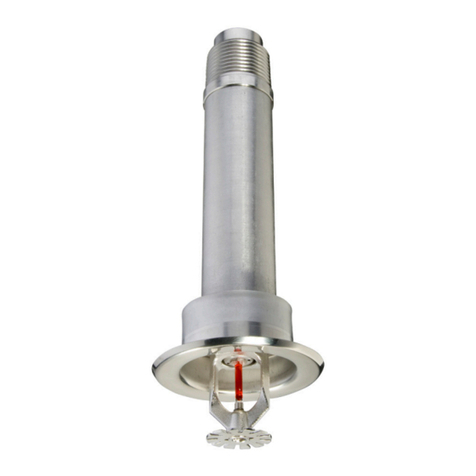
Sprinkler
Installation instructions for the Model
TY920 Electronic Control Pendent
Sprinkler are in technical data sheet
TFP326.
Heat Sensor
Installation instructions for the heat
sensor, including mounting and wiring
requirements, are in the AUTOPULSE
Sprinkler Control Heat Sensor Instal-
lation Instructions (AUTOPULSE doc-
ument number 579-1215AR). These
instructions contain information about
mounting and wiring the sensor.
Smoke Sensor
For information about the smoke sensor
mounting instructions and wiring
requirements, refer to the Installation
Reference section of AUTOPULSE
Multi-Point Peripherals (document
number T-2016294).
System
Commissioning
Before placing the TYCO EAS-1 Elec-
tronically Activated Sprinkler System
ASRS-A Configuration in set condition,
the system must be commissioned.
Commissioning should be performed
after all troubles are cleared from the
EAS-1 Control Unit and the system is
reporting a normal status as indicated
on the Control Unit display.
The system commissioning procedure
should be performed at least once per
system before a system is considered
active. As a consequence of the elec-
tronic control system, testing and com-
missioning without activating sprinklers
must be conducted using EAS-1 Com-
missioning Devices, heating devices
such as the SOLO-461 Heat Detector
Test Head Kit, and a UL and ULC Listed
smoke detector tester.
The EAS-1 Commissioning Device has
the following features:
•
Cable assembly connection port
identical to that of the TYCO Model
TY920 Sprinkler
•
Battery compartment accommo-
dating two AA size batteries
•
On/Off Switch allowing conser-
vation of battery power when the
device is not in use
•
Three LED status lights located at
the end opposite to the connection
port
•
Green LED lights when the device
On/Off switch is placed in the On
position, indicating the device is
ready to begin testing
•
Red LED lights to indicate low
battery power
•
Yellow LED lights for approxi-
mately two minutes during testing
to indicate sprinkler control heat
sensor activation
Test Procedure
Complete the following test procedure
successfully to commission the sprin-
kler system.
Step 1. Disconnect the Cable Assem-
bly from a 6 x 5 grid of TYCO Model
TY920 Sprinklers.
Note: If a 6 x 5 grid of sprinklers is not
available, contact Johnson Controls
Technical Services.
Step 2. Connect the inner 12 Cable
Assemblies to ports of 12 EAS-1 Com-
missioning Devices as shown in Figure
4; and connect a single cable assem-
bly from the outer perimeter of the
6 x 5 test array to the port of a single
EAS-1 Commissioning Device. Set the
On/Off Switch on each commissioning
device to the On position, observing
the Green LED on each is lit, and allow
the devices to hang freely.
Step 3. Use a UL and ULC listed smoke
detector tester on a single smoke
sensor to prompt the EAS-1 Control
Unit to report a fire alarm condition.
Once the EAS-1 Control Unit reports
a supervisory signal from the tested
smoke sensor, proceed to the next
step.
Step 4. Use heating devices to simul-
taneously apply a rapid temperature
increase of at least 20°F/minute rate of
rise to the inner two sprinkler control
heat sensors within the 6 x 5 test array
as shown in Figure 5.
Note: If the inner two sprinkler
control heat sensors cannot be
accessed simultaneously, consult the
Johnson Controls Technical Services
Department.
Step 5. Confirm the Yellow LED is lit
on the EAS-1 Commissioning Devices
connected to all 12 of the inner sprin-
kler control heat sensors, indicating
simulated sprinkler operation.
Step 6. Confirm the Yellow LED is not lit
on the EAS-1 Commissioning Devices
connected to the sprinkler control heat
sensor on the perimeter of the 6 x 5 test
array.
Note: Only 12 of the 13 EAS-1 Commis-
sioning Devices should indicate simu-
lated sprinkler operation for a typical
system. Only 12 out of the 13 Commis-
sioning Devices should be observed
with a Yellow LED lit indicating sprin-
kler operation.
Step 7. Reset the control unit by per-
forming a warm-start, and verify all
solid red LEDs on the heat sensors
return to a blinking state and that a fire
alarm condition is no longer present on
the control unit.
Step 8. To complete the test, unplug
the commissioning devices, and plug
the cable assemblies back into their
corresponding TYCO Model TY920
Sprinklers. Turn the switch on the com-
missioning device to the OFF position
to save battery life.

