TFP213
Page 3 of 4
Hydraulic Design
To determine the hydraulic design for
the Model EC-25 Sprinkler refer to the
applicable FM Global Property Loss
Prevention Data Sheet.
System Type
Wet pipe systems only
Sprinkler Spacing
The maximum coverage area per
sprinkler is 196 ft.² (18,2 m²). The
minimum coverage area per sprinkler is
100 ft.² (9,3 m²). The maximum distance
between sprinklers is 14 feet (4,3 m).
The minimum distance between sprin-
klers is 10 feet (3,05 m).
Note: When a wall or obstruction
makes a minimum spacing of 10 feet
(3,05 m) impossible, consult FM Global
Property Loss Prevention Data Sheet
2.0 for applicable guidelines.
Sprinkler Location
Locate sprinklers with respect to
the ceiling/roof in accordance with
FM Global Property Loss Prevention
Data Sheet 2.0.
Obstructions
Follow the obstruction requirements
as detailed in FM Global Property Loss
Prevention Data Sheet 2.0.
Other Details
All other design details should be in
accordance with FM Global Property
Loss Prevention Data Sheet 2.0 as well
as any other applicable FM Global Data
Sheet.
NFPA 13, Chapter 21 –
Alternative System Design
(CMSA)
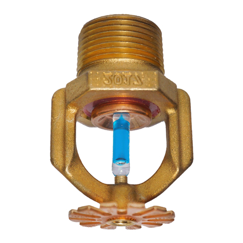
TYCO Model EC-25 Extended Cover-
age Upright Sprinklers (TY9128) have
successfully undergone large-scale
fire tests at FM Global to comply with
Chapter 21 of NFPA 13, 2013 Edition.
As such, Tables 21.2.2 and 21.3.2 of
NFPA 13 may be utilized for design
options with the Model EC-25 Upright
Sprinklers for providing ceiling-only
protection.
This allows for the protection of Pal-
letized, Solid Piled, Bin Box, Shelf, or
Back-to-Back Shelf Storage as well
as Single, Double, and Multiple Row
Open Rack protection of up to 30 feet
(9,1 m) of Cartoned Unexpanded Group
A Plastic Commodities in a maximum
35 feet (11 m) ceiling condition with
extended spacing up to 196 ft.2while
maintaining very reasonable flow and
pressure requirements. Pipe sizes as
well as water supply requirements
can now be kept to a minimum when
compared to other design methods for
high piled storage challenges. Refer to
Tables A and B of this data sheet for
specific flow, pressure, and number of
sprinklers to be calculated.
When used in accordance with NFPA
Chapter 21, smoke vents and draft cur-
tains are not required as specified in the
2015 edition of the International Building
Code (IBC) and International Fire Code
(IFC) for CMSA sprinklers with an RTI of
50 or less and a design of 12 or fewer
sprinklers.
Construction Type
In accordance with NFPA 13 for
Extended Coverage Sprinklers for High
Piled Storage.
Obstruction Criteria
Follow Sections 8.8.5.1, “Extended
Coverage Obstruction Guidelines for
Sprinkler Discharge Pattern Develop-
ment”; 8.12.5.2 and 8.12.5.3, “ESFR
Obstruction Criteria,” for obstructions
that prevent the pattern from reaching
the hazard below.
Exception: When using the Upright
EC-25 Sprinkler, any continuous
obstruction 4 inches (100 mm) or
less shall be permitted to be ignored
in accordance with NFPA 13, section
21.5.3.2.3.
Deflector Distance below Ceiling
Follow NFPA 13, Section 8.8.4 for
allowed deflector distances below
ceiling.
Clearance to Storage
Minimum 36 inches from deflector to
top of storage required.
Maximum Distance
between Sprinklers
14 feet (4,3 m)
Minimum Distance
between Sprinklers
10 feet (3,0 m)
Installation
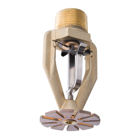
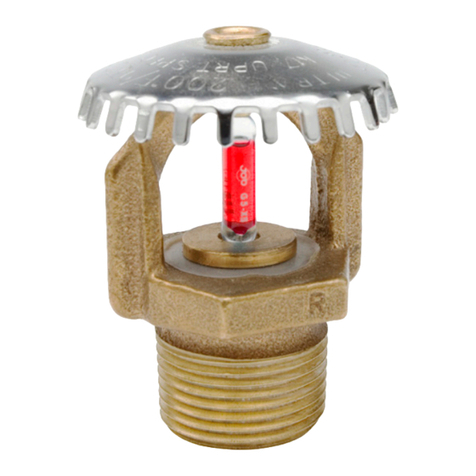
TYCO Model EC-25 Extended Cover-
age 25.2K Upright Sprinklers are to
be installed in accordance with this
section.
Damage to the fusible Link Assembly
during installation can be avoided by
handling the sprinkler using only the
frame arms and the appropriate sprin-
kler wrench. Do not grip or apply any
force to the fusible Link Assembly.
Damaged sprinklers must be replaced
immediately.
A leak-tight 1 inch NPT sprinkler
joint should be obtained by apply-
ing a minimum-to-maximum torque of
20 to 30 lbs.-ft. (26,8 to 40,2 Nm).
Higher levels of torque may distort the
sprinkler inlet with consequent leakage
or impairment of the sprinkler.
Note: Install the Model EC-25 Upright
Sprinkler in the upright position.
Step 1. With pipe thread sealant
applied, hand-tighten the sprinkler into
the sprinkler fitting. Do not apply any
force to the Link Assembly, and handle
the Model EC-25 Sprinkler only by the
Frame arms.
Step 3. Wrench-tighten the Model
EC-25 Sprinkler using only the W-Type
1 Sprinkler Wrench (Ref. Figure 2) and
by fully engaging (seating) the wrench
on the sprinkler wrench flats.
Step 4. After installation, inspect the
Link Assembly of each Model EC-25
Sprinkler for damage. In particu-
lar, verify that the Link Assembly and
Hook are positioned as illustrated in
Figure 1, and that the Link Assembly
has not been bent, creased, or forced
out of its normal position in any way.
Damaged sprinklers must be replaced
immediately.
"FITTING SIDE"
FITTING
TOWARDS SPRINKLER
RECESS
WRENCH
FIGURE 2
W-TYPE 1
SPRINKLER WRENCH
