manuals.online logo
Brands
  1. Home
  2. •
  3. Brands
  4. •
  5. U-Line
  6. •
  7. Ladder
  8. •
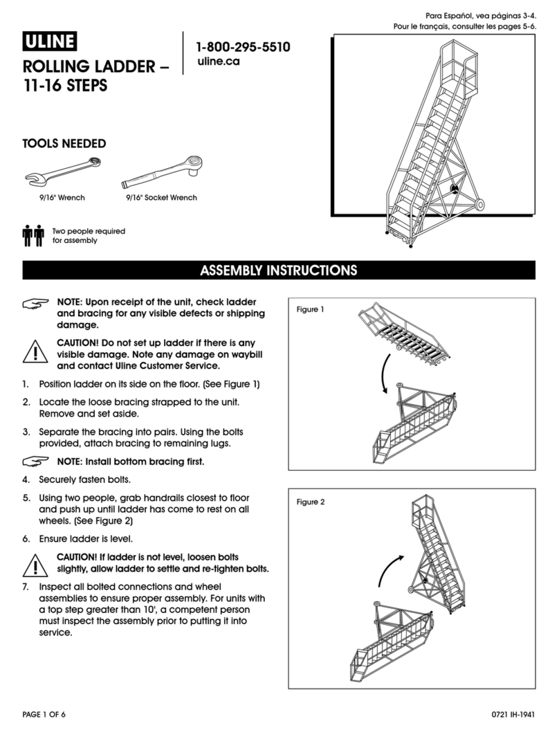
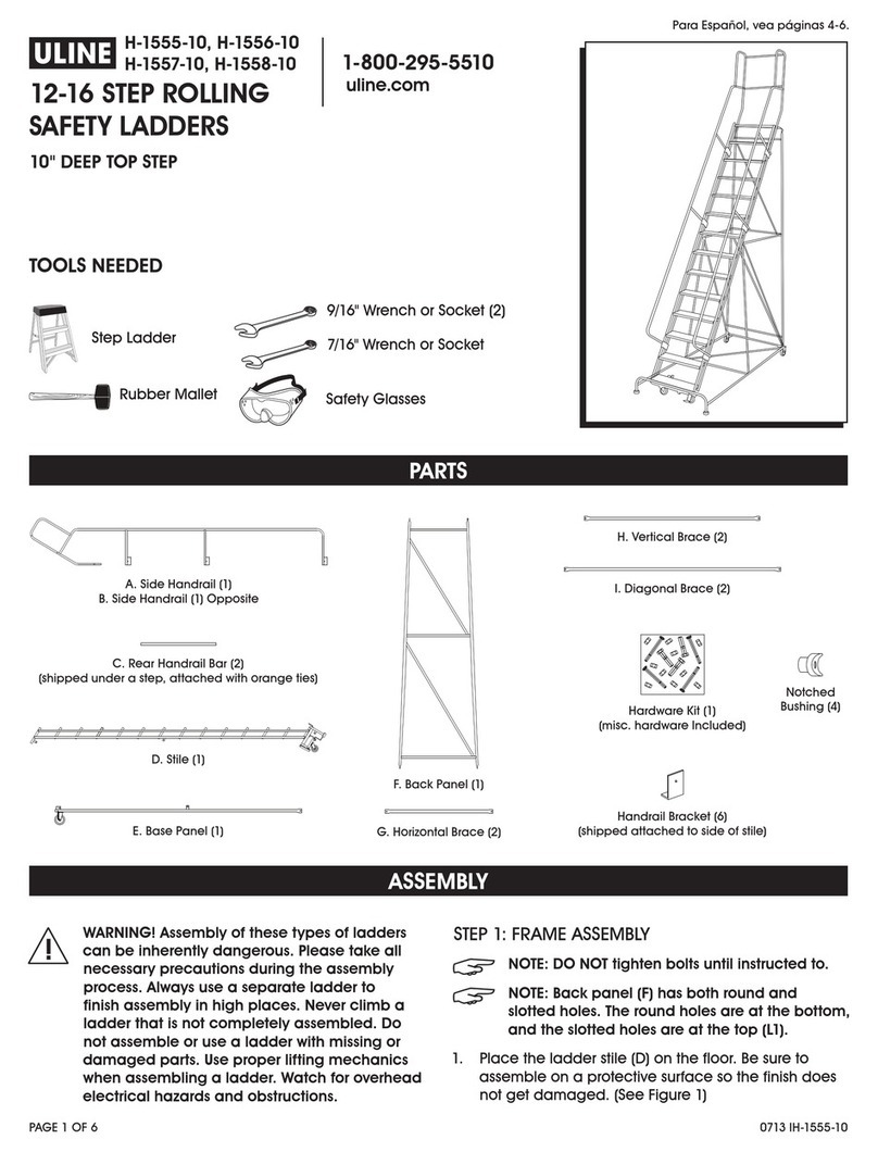
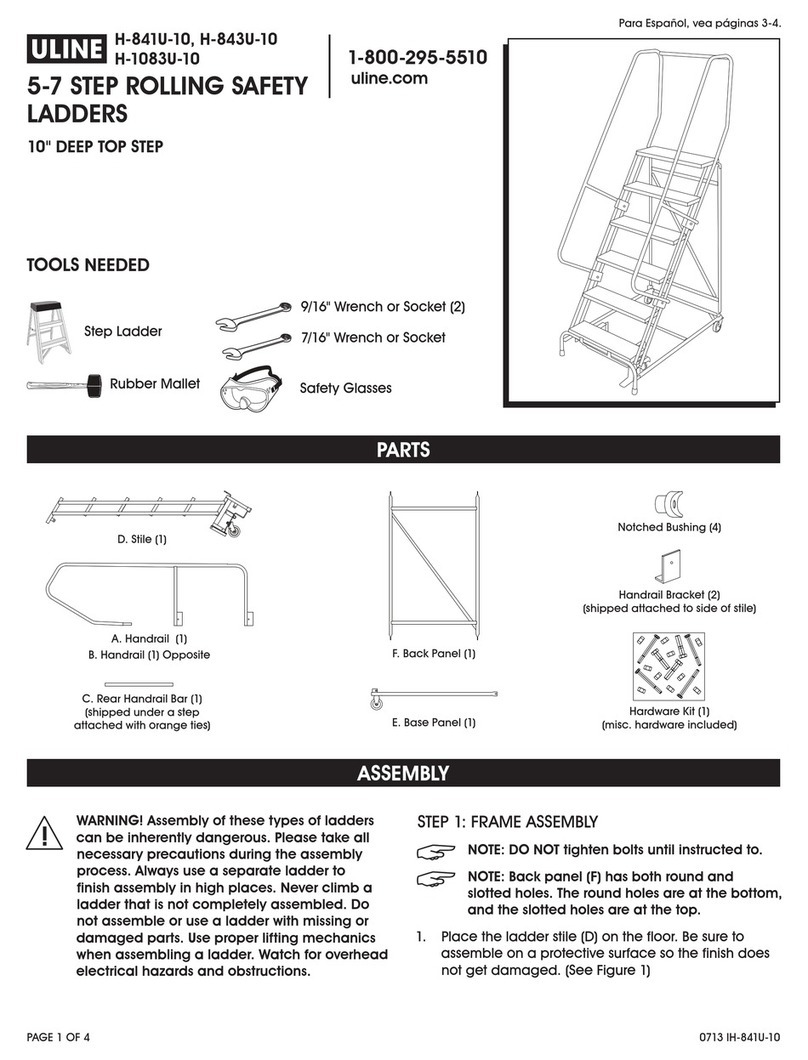
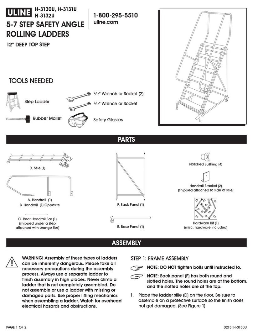
  9. U-Line H-1084U-20 User manual

U-Line H-1084U-20 User manual

0513 IH-1084U-20PAGE 1 OF 3
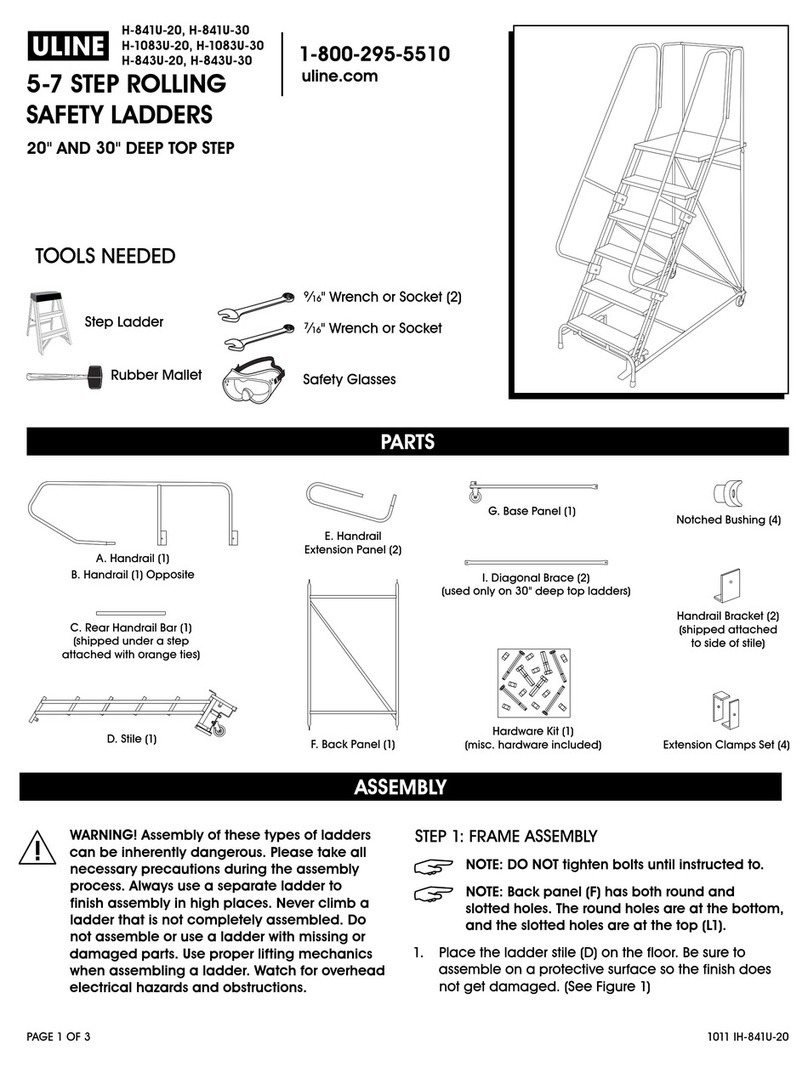
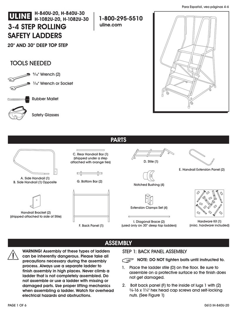
PARTS
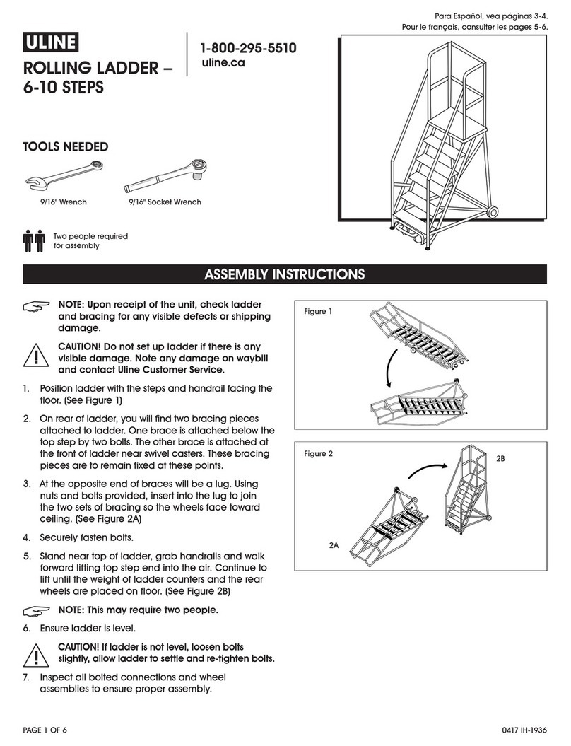
ASSEMBLY
Step Ladder
9⁄16" Wrench or Socket (2)
7⁄16" Wrench or Socket
TOOLS NEEDED
WARNING! Assembly of these types of ladders
can be inherently dangerous. Please take all
necessary precautions during the assembly
process. Always use a separate ladder to
finish assembly in high places. Never climb a
ladder that is not completely assembled. Do
not assemble or use a ladder with missing or
damaged parts. Use proper lifting mechanics
when assembling a ladder. Watch for overhead
electrical hazards and obstructions.
STEP 1: FRAME ASSEMBLY
NOTE: DO NOT tighten bolts until instructed to.
NOTE: Back panel (F) has both round and
slotted holes. The round holes are at the bottom,
and the slotted holes are at the top (L1).
1. Place the ladder stile (D) on the floor. Be sure to
assemble on a protective surface so the finish does
not get damaged. (See Figure 1)
Rubber Mallet Safety Glasses
H-1084U-20, H-1084U-30, H-1085U-20
H-1085U-30, H-1554-20, H-842U-20
H-842U-30, H-844-20, H-844-30
8-12 STEP ROLLING
SAFETY LADDERS
20 AND 30" DEEP TOP STEP
D. Stile (1) G. Horizontal Brace (2)
E. Base Panel (1)
A. Side Handrail (1)
B. Side Handrail (1) (Opposite) Hardware Kit (1)
(misc. hardware
Included)
F. Back Panel (1)
C. Rear Handrail Bar (1)
(shipped under a step attached with orange ties)
Notched
Bushing (2)
J. Handrail Extension Panel (2)
Handrail Bracket (4)
(shipped attached to side of stile)
Handrail Bracket (4)
(shipped attached to side of stile)
H. Vertical Brace (2)
0513 IH-1084U-20PAGE 2 OF 3
STEP 1: FRAME ASSEMBLY CONTINUED
2. Using (6) 3⁄8-16 x 1¼" hex head cap screws &
self-locking nuts, bolt the top (slotted hole) of
back panel (F) to the insides of L1. (See Figure 1)
3. Bolt the bottom (round hole) of back panel (F) & back
of base panel (E) to the insides of L2. Bolt the front of
base panel (E) to the insides of L3. (See Figure 1)
STEP 2: HORIZONTAL AND VERTICAL
BRACE ASSEMBLY
NOTE: DO NOT
tighten bolts until instructed to.
1. Using (3) 3⁄8-16 x 1¼" hex head cap screws, locate
horizontal brace (G) on the outside of L4 & L5.
2. Locate the vertical brace (H) on the outside of L4 & L6.
3. Start (2) self-locking nuts onto screws at L5 & L6.
4. Repeat step 2 for other side.
WARNING! Never climb a ladder that is not
completely assembled.
STEP 3: INSTALL HANDRAILS
NOTE: DO NOT
tighten bolts until instructed to.
1. With ladder on its side, install handrail (A) into the
rear stile tubes. Use the rubber mallet as needed for
mating parts. (See Figure 1).
2. Clamp side handrails to outside of stile tubes using
handrail brackets and 3⁄8-16 x 1¾" hex
head cap
screws and self-locking nuts. (See Figure 2, Step 2)
3. Repeat step 3 with side handrail (B).
ASSEMBLY CONTINUED
Figure 2
STEP 4: INSTALL HANDRAIL EXTENSION PANELS
1. Install the handrail extension panels (J) into support
tubes located on the sides of the platform.
(See Figure 2, Step 3)
2. Clamp handrail extension panel to handrail panels
using extension clamps and 3⁄8-16 x 2" hex head cap
screws & self-locking nuts. (See Figure 2, Step 4)
NOTE: You may now tighten all handrail bolts.
L1
L1 L1
L5
L2
L4
F
E
G
H
D
L6
L3
SINGLE HOLE
MODEL
DOUBLE HOLE
MODEL
L3
L3
SINGLE HOLE
MODEL
DOUBLE HOLE
MODEL
C
SIDE
HANDRAIL
3/8-16
SELF-LOCKING
NUT
TUBE CAP
REAR STILE TUBE
STILE
TUBES
HANDRAIL
HANDRAIL
EXTENSION
CLAMPS
HANDRAIL
BRACKET
J
3/8 -16
SELF-LOCKING
NUT
1/4-20 x 2 3/4"
H.H.C.S.
3/8-16 x 2"
H.H.C.S.
3/8-16 x 2"
H.H.C.S.
NOTCHED
BUSHING
REAR
HANDRAIL
BAR
STEP 5 STEP 4 STEP 1 STEP 2
DA, B
HANDRAIL
BRACKET
SUPPORT
TUBE
STEP 3
0513 IH-1084U-20PAGE 3 OF 3
ASSEMBLY CONTINUED
Step 5: INSTALL REAR HANDRAIL BARS
1. Detach rear handrail bar (C) from under a step by
clipping orange ties.
2. Insert notched bushing into each end of rear
handrail bars (C). (See Figure 2, Step 3)
3. Position rear handrail bars between mounting holes
on the top part of side handrails using (4) ¼-20 x 2¾"
hex head cap screws.
NOTE: You may now tighten all handrail bolts
.
STEP 6: LEVEL LADDER
1. Stand ladder upright on level.
2. Activate safelock by stepping on the trip bar
located in front of the first step.
3. This sets the ladder on the feet to level.
4. When steps are level, tighten all installed bolts.
NOTE: You may now tighten all handrail bolts
.
π CHICAGO • ATLANTA • DALLAS • LOS ANGELES • MINNEAPOLIS • NYC/PHILA • SEATTLE • MEXICO • CANADA
1-800-295 - 5510
uline.com

This manual suits for next models

8

Other U-Line Ladder manuals

U-Line H-1936 User manual

U-Line

U-Line H-1936 User manual

U-Line H-840U-20 User manual

U-Line

U-Line H-840U-20 User manual

U-Line H-1555-10 User manual

U-Line

U-Line H-1555-10 User manual

U-Line U-840U-10 User manual

U-Line

U-Line U-840U-10 User manual

U-Line H-841U-10 User manual

U-Line

U-Line H-841U-10 User manual

U-Line H-841U-20 User manual

U-Line

U-Line H-841U-20 User manual

U-Line H-7903 User manual

U-Line

U-Line H-7903 User manual

U-Line H-1941 User manual

U-Line

U-Line H-1941 User manual

U-Line H-5592 User manual

U-Line

U-Line H-5592 User manual

U-Line H-3797 User manual

U-Line

U-Line H-3797 User manual

U-Line H-840U-10 User manual

U-Line

U-Line H-840U-10 User manual

U-Line H-3130U User manual

U-Line

U-Line H-3130U User manual

Popular Ladder manuals by other brands

INNOVAPLAS Lumi-o BILTMOR DECK 5050 manual

INNOVAPLAS

INNOVAPLAS Lumi-o BILTMOR DECK 5050 manual

Lofts & Ladders HIGH CLEARANCE UNIT Assembly instructions

Lofts & Ladders

Lofts & Ladders HIGH CLEARANCE UNIT Assembly instructions

Hailo 1707709 manual

Hailo

Hailo 1707709 manual

pixima fontanot RING TUBE Assembly instructions

pixima fontanot

pixima fontanot RING TUBE Assembly instructions

AmazonBasics B07WJWRDFW quick start guide

AmazonBasics

AmazonBasics B07WJWRDFW quick start guide

Parker PTL-3200 owner's manual

Parker

Parker PTL-3200 owner's manual

Batavia GIRAFFE AIR BT-TL010 operating instructions

Batavia

Batavia GIRAFFE AIR BT-TL010 operating instructions

Roto Columbus profiLine F30 installation instructions

Roto

Roto Columbus profiLine F30 installation instructions

Hailo FlexLine T80 Instructions for use

Hailo

Hailo FlexLine T80 Instructions for use

pixima fontanot RING Assembly instructions

pixima fontanot

pixima fontanot RING Assembly instructions

CSH PUTNAM instruction manual

CSH

CSH PUTNAM instruction manual

FVC SP0207B installation guide

FVC

FVC SP0207B installation guide

Bilco BL-Z Installation

Bilco

Bilco BL-Z Installation

Vestil ATS-6-56 owner's manual

Vestil

Vestil ATS-6-56 owner's manual

KRAUSE 916105 Instructions for assembly and use

KRAUSE

KRAUSE 916105 Instructions for assembly and use

Sealey Power Products LAD002 instructions

Sealey

Sealey Power Products LAD002 instructions

Batavia Giraffe Air BT-TL008 operating instructions

Batavia

Batavia Giraffe Air BT-TL008 operating instructions

sellwood Attic Ladders A25 installation instructions

sellwood

sellwood Attic Ladders A25 installation instructions

manuals.online logo
manuals.online logoBrands
  • About & Mission
  • Contact us
  • Privacy Policy
  • Terms and Conditions

Copyright 2025 Manuals.Online. All Rights Reserved.