manuals.online logo
Brands
  1. Home
  2. •
  3. Brands
  4. •
  5. U-Line
  6. •
  7. Ladder
  8. •
  9. U-Line H-840U-10 User manual

U-Line H-840U-10 User manual

1011 IH-840U-10PAGE 1 OF 2
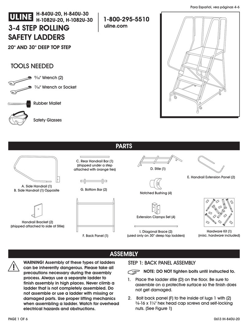
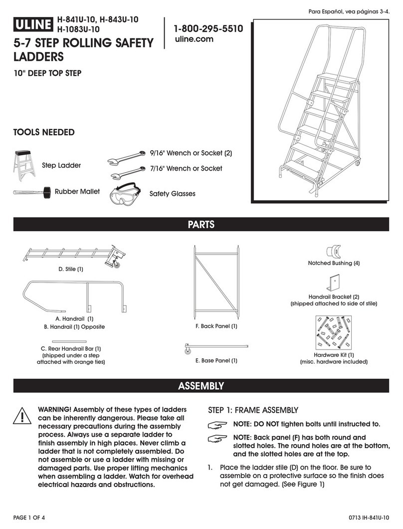
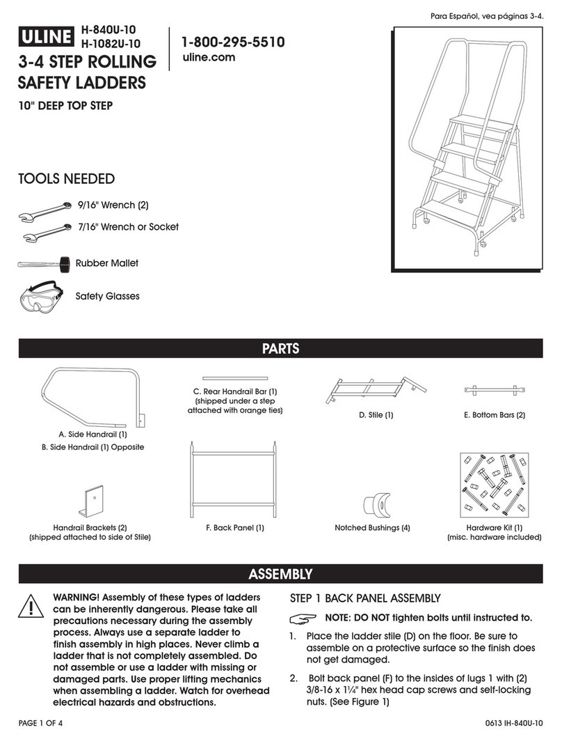
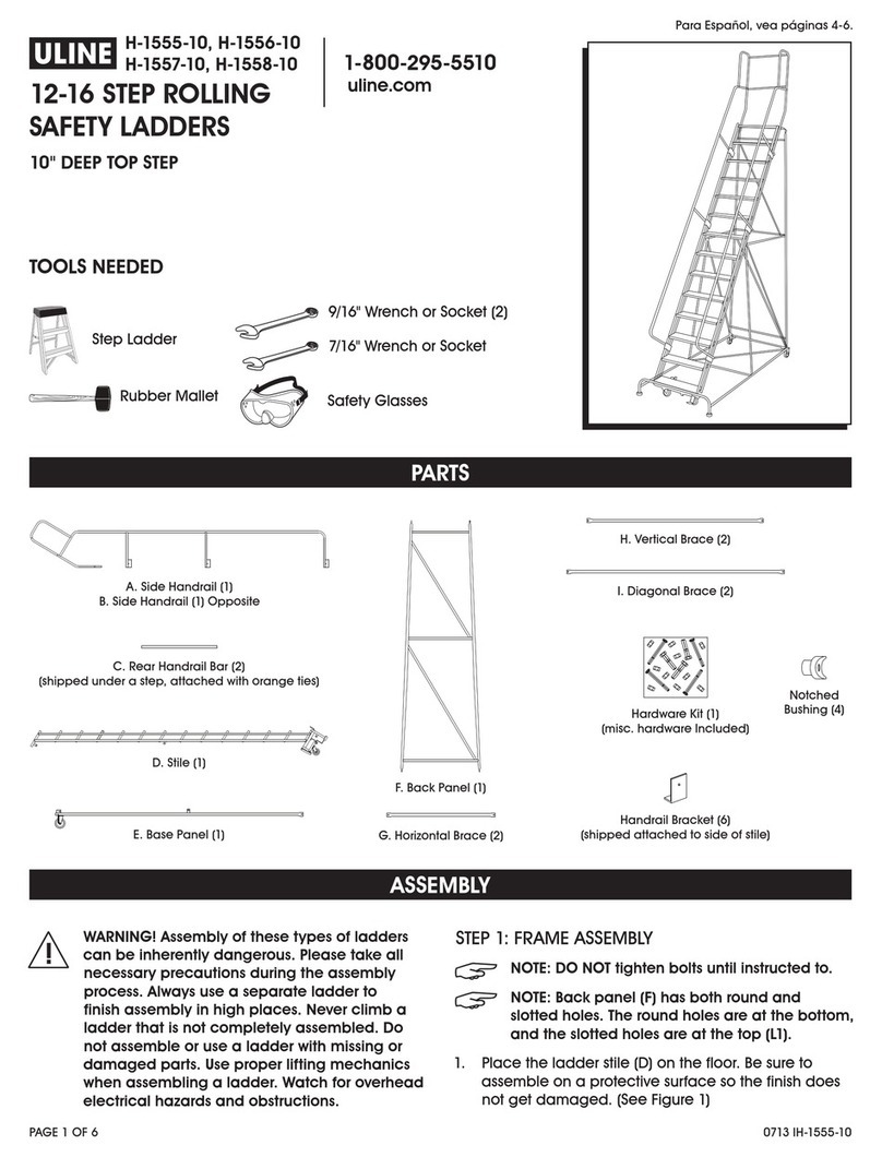
PARTS
ASSEMBLY
9⁄16" Wrench (2)
7⁄16" Wrench or Socket
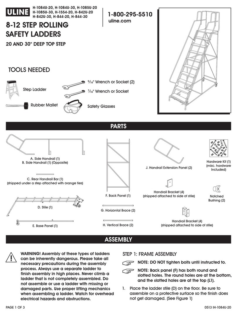
A. Side Handrail (1)
C. Rear Handrail Bar (1)
(shipped under a step
attached with orange ties)
B. Side Handrail (1) Opposite
Handrail Brackets
(shipped attached to side of Stile)
Notched Bushings (4)
D. Stile (1)
F. Back Panel (1)
Hardware Kit (1)
(misc. hardware included)
E. Bottom Bars (2)
TOOLS NEEDED
WARNING! Assembly of these types of ladders
can be inherently dangerous. Please take all
precautions necessary during the assembly
process. Always use a separate ladder to
finish assembly in high places. Never climb a
ladder that is not completely assembled. Do
not assemble or use a ladder with missing or
damaged parts. Use proper lifting mechanics
when assembling a ladder. Watch for overhead
electrical hazards and obstructions.
STEP 1: BACK PANEL ASSEMBLY
NOTE: DO NOT tighten bolts until instructed to.
1. Place the ladder stile (D) on the floor. Be sure to
assemble on a protective surface so the finish does
not get damaged.
2. Bolt back panel (F) to the insides of lugs 1 with (2)
3⁄8-16 x 1¼" hex head cap screw and self-locking
nuts. (See Figure 1)
Rubber Mallet
Safety Glasses
H-840U-10
H-1082U-10
3-4 STEP ROLLING
SAFETY LADDERS
10" DEEP TOP STEP
1011 IH-840U-10PAGE 2 OF 2
ASSEMBLY CONTINUED
STEP 2: ASSEMBLY OF BOTTOM BARS
1. Bolt bottom bar (E) to the insides of lugs 3 with (2)
3⁄8-16 x 1¼" hex head cap screw and self-locking
nuts. (See Figure 1)
2. Bolt other end of bottom bar (E) to the inside of
lug 2 on back panel. (See Figure 1)
3. Repeat on opposite side with other bottom bar.
4. If rubber tips have not been installed prior to
shipping, slip rubber tips onto the ends of the legs.
C
REAR
HANDRAIL
BAR
NOTCHED
BUSHING
SIDE
HANDRAIL
STILE
TUBES
TUBE CAP
STEP 1 STEP 2
HANDRAIL
REAR STILE
TUBE
¼-20 x 2¾"
3/8-16 x 2"
H.H.C.S.
3/8-16
SELF-LOCKING NUT
STEP 3
A B
D
HANDRAIL
HANDRAIL
BRACKET
Figure 2
Figure 1
STEP 3: INSTALL HANDRAILS
CAUTION: NEVER climb a ladder that is not
completely assembled.
1. Install side handrail (A) into the rear stile tubes. Use
the rubber mallet as needed for mating parts.
(See Figure 2, Step 1)
2. Detach handrail brackets that are shipped attached
to side of stile. (See Figure 2, Step 2)
3. Clamp side handrail to outside of stile tubes using
detached handrail brackets and 3⁄8-16 x 1¼" hex
head cap screws and self-locking nuts.
(See Figure 2, Step 2)
4. Repeat step 1 through 3 with handrail (B).
5. Detach near handrail bar (C) from under a step by
clipping orange ties.
6. Insert notched bushing into each end of rear
handrail bar (C).
7. Position rear handrail bar between mounting holes
of side handrails (A) and (B). Attach using ¼-20 x 1¼"
hex head cap screws. (See Figure 2, Step 3)
NOTE: You may now tighten all handrail bolts.
STEP 4: LEVEL LADDER
1. Stand ladder upright, on level surface.
2. Weight ladder to compress casters making sure
ladder rests level on all four legs.
3. When steps are level, tighten all installed bolts.
D
F
LUG 1
LUG 2
LUG 3
BRAKE HOUSING
E
This manual suits for next models

1

Other U-Line Ladder manuals

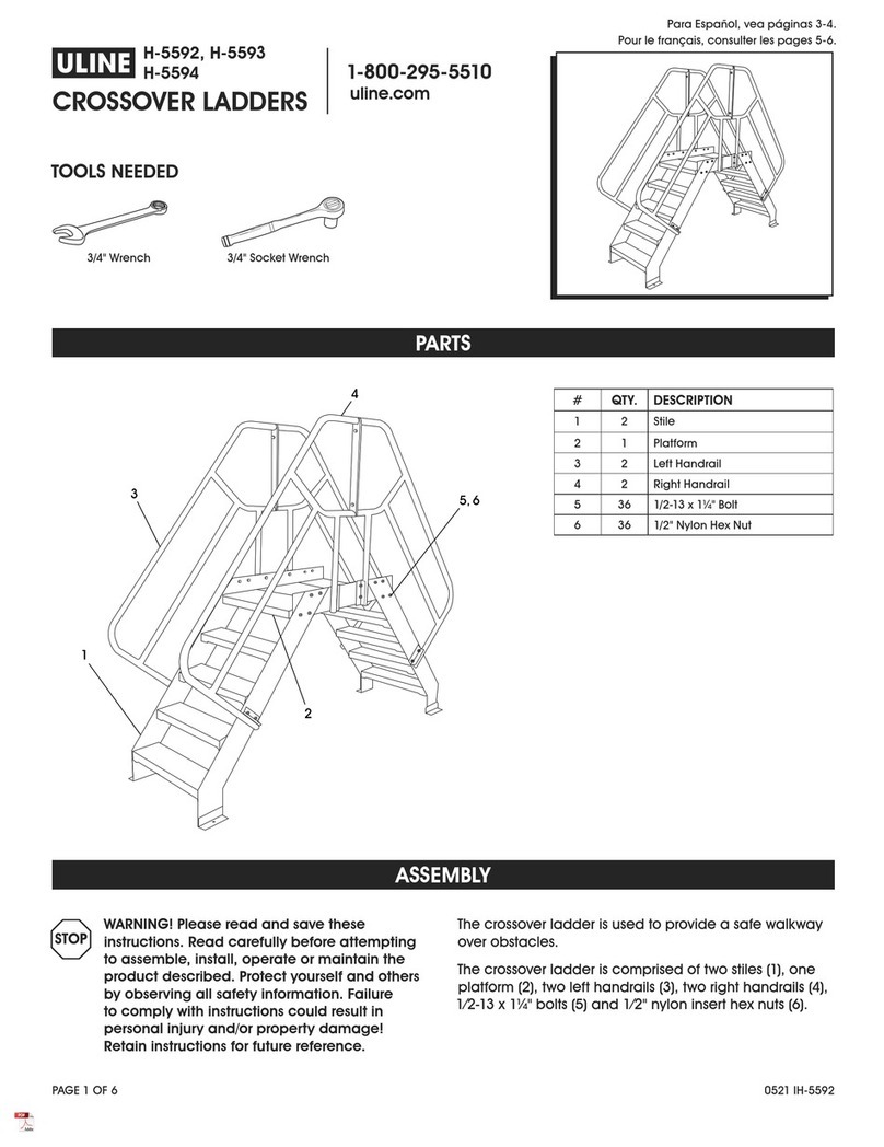
U-Line H-5592 User manual

U-Line

U-Line H-5592 User manual

U-Line H-1084U-20 User manual

U-Line

U-Line H-1084U-20 User manual

U-Line H-840U-20 User manual

U-Line

U-Line H-840U-20 User manual

U-Line H-1555-10 User manual

U-Line

U-Line H-1555-10 User manual

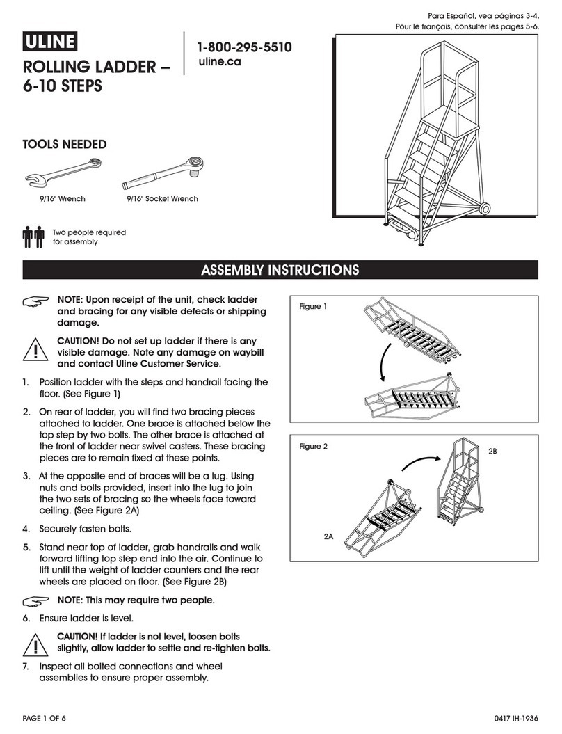
U-Line H-1936 User manual

U-Line

U-Line H-1936 User manual

U-Line U-840U-10 User manual

U-Line

U-Line U-840U-10 User manual

U-Line H-841U-10 User manual

U-Line

U-Line H-841U-10 User manual

U-Line H-1941 User manual

U-Line

U-Line H-1941 User manual

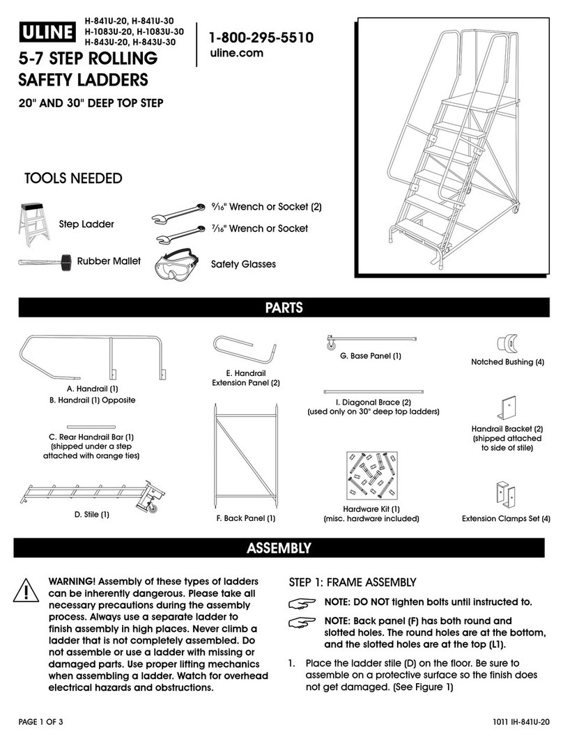
U-Line H-841U-20 User manual

U-Line

U-Line H-841U-20 User manual

U-Line H-7903 User manual

U-Line

U-Line H-7903 User manual

U-Line H-3797 User manual

U-Line

U-Line H-3797 User manual

U-Line H-3130U User manual

U-Line

U-Line H-3130U User manual

Popular Ladder manuals by other brands

Wireworks Slatted Stool Assembly instructions

Wireworks

Wireworks Slatted Stool Assembly instructions

Hailo FlexLine Series Use and Operating Instructions

Hailo

Hailo FlexLine Series Use and Operating Instructions

GORILLA LADDERS GLMPXA-14 Operating/safety instructions

GORILLA LADDERS

GORILLA LADDERS GLMPXA-14 Operating/safety instructions

Hailo TP1 Use and Operating Instructions

Hailo

Hailo TP1 Use and Operating Instructions

Werner Telescopic Extension Ladder Series instruction manual

Werner

Werner Telescopic Extension Ladder Series instruction manual

Misterstep TECH CE installation instructions

Misterstep

Misterstep TECH CE installation instructions

Kelfort 1518855 manual

Kelfort

Kelfort 1518855 manual

Zico LMS Parts and instruction manual

Zico

Zico LMS Parts and instruction manual

Trigano J-C9305 Assembling instructions

Trigano

Trigano J-C9305 Assembling instructions

FrontLine RLA18B manual

FrontLine

FrontLine RLA18B manual

Youngman Adjusta-Minit user guide

Youngman

Youngman Adjusta-Minit user guide

STABILOMAT SBT-TL008 Translation of the original instructions

STABILOMAT

STABILOMAT SBT-TL008 Translation of the original instructions

Fontanot Klio Series Assembly instructions

Fontanot

Fontanot Klio Series Assembly instructions

Confer Plastics EVOLUTION 7100 Assembly and installation manual

Confer Plastics

Confer Plastics EVOLUTION 7100 Assembly and installation manual

Würth 0962 931 410 Assembly instruction

Würth

Würth 0962 931 410 Assembly instruction

MONDELIN GARDIA 202100 user manual

MONDELIN

MONDELIN GARDIA 202100 user manual

Powerfix Profi HG01091 Assembly, operating and safety instructions

Powerfix Profi

Powerfix Profi HG01091 Assembly, operating and safety instructions

Vestil LAD-EZ Series instruction manual

Vestil

Vestil LAD-EZ Series instruction manual

manuals.online logo
manuals.online logoBrands
  • About & Mission
  • Contact us
  • Privacy Policy
  • Terms and Conditions

Copyright 2025 Manuals.Online. All Rights Reserved.