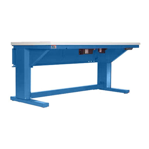
U-Line H-8184 User manual

PAGE 1 OF 39 0920 IH-8184
H-8184, H-8185 1-800-295-5510
uline.com
ADJUSTABLE HEIGHT
WORKBENCH
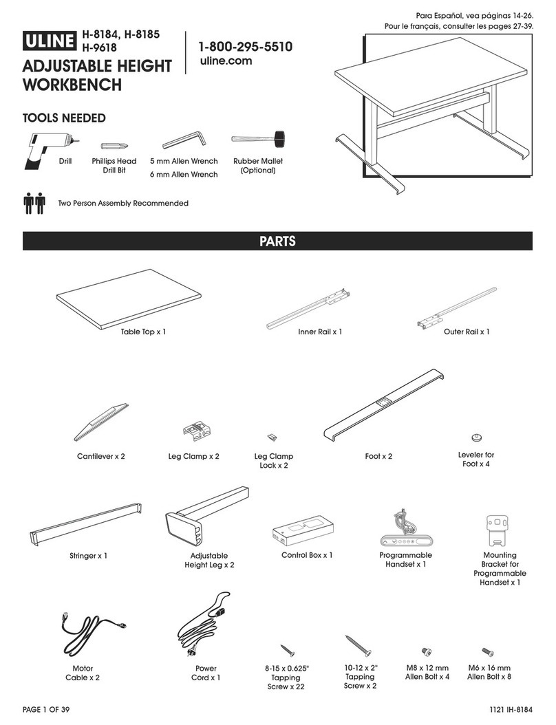
TOOLS NEEDED
Drill Phillips Head
Drill Bit
Table Top x 1
Foot x 2
Motor
Cable x 2
Inner Rail x 1
Leveler for
Foot x 4
Power
Cord x 1
Outer Rail x 1
Cantilever x 2
8-15 x 0.625"
Tapping
Screw x 22
Leg Clamp x 2
10-12 x 2"
Tapping
Screw x 2
M8 x 12 mm
Allen Bolt x 4
Leg Clamp
Lock x 2
Stringer x 1 Adjustable
Height Leg x 2
Control Box x 1 Programmable
Handset x 1
Mounting
Bracket for
Programmable
Handset x 1
M6 x 16 mm
Allen Bolt x 8
5 mm Allen Wrench
6 mm Allen Wrench
Rubber Mallet
(Optional)
PARTS
Two Person Assembly Recommended
Para Español, vea páginas 14-26.
Pour le français, consulter les pages 27-39.

PAGE 2 OF 39 0920 IH-8184
SAFETY
NOTE: Count and inspect all pieces before
disposing of any carton or packing materials.
CAUTION! Adjustable legs are heavy and care
should be used when moving them during
assembly.
WARNING! Failure to comply with these
instructions may result in accidents involving
serious personal injury.
NOTE: Failing to follow these instructions can
result in the product being damaged or being
destroyed.
Safe use of the system is possible only when the
operating instructions are read completely and the
instructions are strictly observed.
CAUTION! It is important for everyone
connecting, installing or using the product to
have the necessary information and access
to these instructions. Follow the instructions
for mounting – there is a risk of injury if these
instructions are not followed.
CAUTION! The product is not intended for use
by young children or infirm persons without
supervision.
CAUTION! If there is visible damage to the
product, do not install it.
CAUTION! During construction of applications
in which the actuator is to be fitted, there must
be no possibility of personal injury, for example
squeezing of fingers or arms.
NOTE: Ensure free space for movement of the
product in both directions to avoid blockades.
CAUTION! Persons who do not have the
necessary experience or knowledge of the
product/products must not use the product/
products.
CAUTION! Persons with reduced physical,
sensory or mental abilities must not use the
product/products, unless they are under
surveillance or they have been thoroughly
instructed in the use of the apparatus by a
person who is responsible for the safety of
these persons.
CAUTION! Children must be supervised.
CAUTION! It is the operator's responsibility
before operating to ensure that there is free
space for the application to move without risk
for the operator or bystanders.
CAUTION! Do not overload the actuators – this
can cause personal injury and damage to the
system.
CAUTION! Do not use the workbench for lifting
persons. Do not sit or stand on a table while
operating.
CAUTION! Do not use the system in
environments other than the intended indoor
use.
BEFORE INSTALLATION, RE-INSTALLATION
OR TROUBLESHOOTING
• Stop the columns.
• Switch off the power supply and pull out the power
plug.
• Relieve the columns of any loads, which may be
released during the work.
BEFORE START-UP
• Make sure that the system has been installed as
instructed in these instructions.
• Make sure that the voltage of the control box is
correct before connecting the system to the power
supply.
• The individual parts must be connected before
connecting the control box to the power.
DURING OPERATION
• If the control box makes unusual noise or smells,
remove the power plug immediately.
• Ensure the cables are not damaged.
• Unplug the power cable on mobile equipment
before moving it.
PAGE 3 OF 39 0920 IH-8184
1. Place table top upside down on a smooth,
non-marring surface. Place inner rail and outer
rail on top of the table top, with the outer rail
overlapping the inner rail. (See Figure 1)
NOTE: Exposed side of inner/outer rails should
face the bullnose edge of tabletop.
2. Slide cantilevers onto base of inner and outer rails.
Align middle marker on cantilever with center on
inner/outer rail. (See Figure 2)
NOTE: A rubber mallet may be needed to assist.
3. Extend rails to required length.
NOTE: Distance from outside of cantilevers should
be approximately 56" apart for 60" workbenches
and 68" apart for 72" workbenches. Placement
is for reference when aligning stringer later in
assembly.
4. Place adjustable height legs inside of cradle
located at the end of each rail. Legs have slots on
backside of housing which should insert into notches
of each rail. (See Figure 3)
5. Place leg clamps over adjustable height leg
housing. Gently push down on clamp to lock into
place. (See Figure 4)
ASSEMBLY
Inner Rail
Outer Rail
Figure 1
Base of Rail
Cantilever Middle
Marker
Figure 2
Inner Rail
Outer Rail
Adjustable
Height Leg
Slots
of Leg
Notches
of Rail
Figure 3
Figure 4

PAGE 4 OF 39 0920 IH-8184
6. Insert leg clamp lock into trapezoid hole on top of
leg clamp. While short end is inserted, using your
foot, step onto the longer end and apply pressure to
snap the lock into place. Repeat for other side.
(See Figure 5)
NOTE: Short end must be inserted first.
NOTE: Arrow on lock must face arrow on clamp.
7. Position stringer in-between adjustable height legs
and align with threaded holes on side of each leg.
Attach stringer to legs using two M8 x 12 mm Allen
bolts for each side. Fasten using 6 mm Allen wrench.
(See Figure 6)
NOTE: Do not tighten all the way because
stringer will be removed at a later step.
NOTE: Protruding end of stringer should be
facing the back side (square edge) of table
top.
8. Fasten cantilevers to tabletop with four 8-15 x 0.625"
tapping screws per cantilever. (See Figure 7)
9. Fasten one additional 8-15 x 0.625" tapping screw to
outside of each adjustable leg cradle. (See Figure 8)
10. Center the assembly onto the workbench top. Using
drill with Phillips head drill bit, fasten assembly to
workbench top with five 8-15 x 0.625" tapping screws
through exposed holes along inner and outer rails.
(See Figure 9)
ASSEMBLY CONTINUED
Figure 5
Figure 9
Figure 8
Figure 6
Figure 7
Protruding End

PAGE 5 OF 39 0920 IH-8184
ASSEMBLY CONTINUED
11. Remove stringer. Fasten back side of assembly to
workbench top with five 8-15 x 0.625" tapping screws
through exposed holes along inner/outer rails.
(See Figure 10) Replace stringer as in step 6.
12. Place control box at center of assembly against
inner/outer rails on the exposed side. Secure control
box to table top using Phillips head drill and two
10-12 x 2" tapping screws. (See Figure 11)
13. Connect one motor cable into end of control Box
slot marked "1" and second motor cable into slot
marked "2." Then connect other end of motor cables
to each adjustable height leg by inserting cable
into white cable slot. (See Figure 12)
14. Connect the power for the control box by inserting
power cord into slot designated as "AC."
(See Figure 13)
15. The inner/outer rails feature a cable management
tray. Tuck the loose cords into the cable
management tray to hide them. (See Figure 14)
16. Position mounting bracket for programmable handset
at the front edge of the table top in desired position.
Bracket should face upward. Secure to table top using
Phillips head drill and two 8-15 x 0.625" tapping screws.
(See Figure 15)
Fi gu re 11
Figure 12
Figure 13
Figure 14
Figure 15
Figure 10

PAGE 6 OF 39 0920 IH-8184
ASSEMBLY CONTINUED
17. Slide programmable handset onto bracket and
snap into place. Insert handset cable into slot
marked "A1" on control box. (See Figure 16)
18. Attach foot to adjustable height leg using four
M6 x 16 mm Allen bolts. Tighten using 5 mm Allen
wrench. Repeat with other foot and leg.
(See Figure 17)
19. Mount levelers for foot and turn clockwise by hand
to secure. (See Figure 18)
20. Desk is now fully assembled. Using two people,
carefully flip the desk upright onto its feet.
21. Plug power cord into outlet. Follow operation
instructions to initialize the desk prior to first use.
Figure 17
Figure 18
Figure 16

PAGE 7 OF 39 0920 IH-8184
NOTE: The workbench must be initialized prior
to first use.
• To initialize, press and hold the down button on the
handset until the desk reaches its lowest height,
slightly raises and stops.
• Release the down button. The desk is now ready to use.
NOTE: The desk may need to be reset from
time to time to work properly. Unplug the power
cord for 20 seconds, plug back in and follow
the initialization process to reset desk.
CAUTION! Make sure there are no obstacles in
the desk's height adjustment path, and make
sure the desk is not touching any walls.
CAUTION! Make sure all cords are at the
appropriate length to accommodate changes
in height.
HEIGHT ADJUSTMENT
• Press the up button to raise the desktop.
• Press the down button to lower the desktop.
• Release button to stop movement.
SETTING HEIGHT ON DISPLAY
• Measure height from floor to top of workbench top.
• Press and hold up and down buttons until dotted
line appears and the numbers re-appear on the
display.
• Use up and down buttons to change the figure to
the actual measured height. Once complete, allow
time for numbers to flash confirming new height.
PROGRAMMING PRESET HEIGHT
• Use up and down buttons to move desk to the
desired position.
• Press the "S" button. The display will flash for two
seconds. Within two seconds, press one of the preset
position buttons and position will be stored.
• The panel will acknowledge by showing "1," "2" or "3"
in the display depending on the chosen preset.
• Up to three preset positions can be programmed.
• Press one of the preset position buttons and the
workbench will start to adjust to the stored position.
Hold the button until the position is reached.
OPERATION
CONTROLS
Up
Button
Down
Button
Store Position
Button
DisplayThree Preset
Position Buttons

PAGE 8 OF 39 0920 IH-8184
OPERATING ISSUE RECOMMENDATIONS
System will move down but not up. See Initialize the Control Box, above.
System unresponsive (no power to
display with any button is pressed).
If any of these steps activates the
digital display, initialize the system.
1. Check power cable connection.
2. Test power outlet using another device.
3. Plug in and test a new switch.
4. Connect all cables to a new control box and test.
System is powered, but will not
initialize.
1. Press and release the down button a few times before pressing
and holding for five seconds.
2. The control box may have a special configuration. If the
workbench is programmed with a lower stroke limit, it may have
a longer Forced Initialization Time (time required to hold down
button before initialization). Can be 10 seconds or longer.
3. The problem could be a faulty desk leg or a faulty motor cable.
For a standard control box without special configuration, initialize
each leg in Channel 1 with nothing else plugged into the motor
channels on the control box. Swap the motor cables so that a
different motor cable is used to initialize Channel 1.
TROUBLESHOOTING
INITIALIZE THE CONTROL BOX
1. Hold down button on handset to ensure the
workbench is retracted to its lowest height.
2. Briefly release down button.
3. Press and hold down button for five seconds, wait
until workbench stops moving and then release.
a. If initialization is successful, user should see a
slight up/down handshake movement of the
workbench legs.
b. If you have a workbench panel with display, user
will also see E01.
CHECK ALL CABLE CONNECTIONS
1. Check that cables are connected to control box
and power outlet.
2. Check that all motor cables are connected to
control box and leg.
a. Assuming a standard control box configuration,
these must be connected in channels 1 and 2.
They cannot be connected in channels 1 and 3
or 2 and 3 unless there is a configuration on the
control box specifying this arrangement.
3. Check that programmable handset cable is
connected to the control box in either port A1 or A2.
CHECK FOR OBSTRUCTIONS
1. Check under, above and on the sides of the desk
for any obstructions that could prevent movement
in either direction.
CHECK FOR FAULTY COMPONENTS WITH
ERROR CODES ON DIGITAL DISPLAY
1. Check the error code list on page 10. The code
should read E##. Some error codes are channel-
specific which can help pinpoint the problem.

PAGE 9 OF 39 0920 IH-8184
OPERATING ISSUE RECOMMENDATIONS
Channel-specific error (Ex: E41 –
Channel 1 overload) – Everything
except PIEZO errors (E59-E63).
1. Swap the motor cable connections at the control box. If It
remains E41, there could be a problem with the workbench or a
bad control box. If the error changes to E42, go to step 2.
2. Swap the motor cable connections at the desk legs, so the leg
that was originally connected to Channel 1 is back in Channel
1, but with the motor cable that was originally connected to
Channel 2. If it remains E42, it is most likely a bad motor cable. If
it goes back to E41, it is most likely a bad leg.
Desk is uneven. 1. Initialize the control box, see page 8. If both legs begin to run down,
complete the initialization. If only one leg moves, stop and move to
Step 2.
2. Check motor cable connections. Check to ensure motor cables
are not pulled during movement. With a standard, Plug & Play
control box, it is possible that only one leg is connected, and
connected to Channel 1. In this case, it will initialize and run
Channel 1 only. If there is only one leg but it is connected to
Channel 2, it will not initialize.
3. If a motor cable was disconnected, try initializing again. If
unsuccessful, connect the desk leg from Channel 2 into Channel
1, with nothing in Channel 2, and initialize.
4. Try initializing the same leg in Channel 1, but with a different
motor cable. If it still won't initialize, contact Uline Customer
Service at 1-800-295-5510.
TROUBLESHOOTING CONTINUED

PAGE 10 OF 39 0920 IH-8184
ERROR CODES
ERROR CODE DESCRIPTION CAUSES RECOMMENDATIONS
E01 The desk has an unknown
position and needs to be
initialized.
Position error.
New desk leg added.
Initialize the system.
E02 Overload in upward
direction has occurred.
Obstruction.
Bad leg or motor cable.
Check all cable
connections, initialize the
system.
Troubleshoot components
by initializing one at a time.
E03 Overload in downward
direction has occurred.
Obstruction.
Bad leg or motor cable.
Check all cable
connections, initialize the
system.
Troubleshoot components
by initializing one at a time.
E08 Indicate that software failed
to kick watchdog.
Program fault. Unplug cable for fifteen
seconds.
Initialize the system.
Replace control box.
E09 Collisions detected on the
LINBUS.
Key pressed on two or
more connected handset
simultaneously.
Multiple LINBUS devices
activated.
Check if another desk panel
is connected and being
activated.
Unplug all but one desk
panel and test system.
E10 Power fail happened, or
power regulator adjusted
below 10%.
Power cord pulled during
driving.
Internal fault.
Only 1 battery for a 3- or
4-channel system.
Power fail, voltage on power
supply drops below a certain
limit, power removed.
Check cable is not caught,
and is allowed to freely
travel.
Use strain-relief loop built
into control box.
Use a second battery or
charge batteries.
E11 Change in number of
actuators since initialization.
Disconnection.
Desk Leg added.
Check motor cable
connections and Integrity.
Change motor cable or
desk leg.
Initialize the system.

PAGE 11 OF 39 0920 IH-8184
ERROR CODE DESCRIPTION CAUSES RECOMMENDATIONS
E12 One channel have position
different than others.
Too much back drive
occurred.
Move table to fully retracted
position.
Initialize system.
E13 Short circuit detected during
operation.
Squeezed motor cable.
Short in motor.
Check motor cable
connections.
Isolate and replace motor
cable.
Isolate and replace desk
leg.
E15 System has reached its
power limitation.
Power cord pulled during
driving.
Internal fault.
Many times will see this
alongside E10.
Power regulator has
adjusted speed down
on actuators without any
significant current draw,
usually caused by power
supply dropping.
Check mains cable is not
caught, and is allowed to
freely travel.
Use strain-relief loop built
into control box.
E16 Illegal keys pressed
(handled internally in DP1C).
Hitting multiple buttons
simultaneously.
Check desk panel.
E17 LINBUS unit does not support
safety feature.
DP1C/DPF1C does not have
up-to-date software.
Try DP with more recent
software version (printed on
label).
E18 A special service tool is
required to change number
of channels to the system.
Baselift only – Service tool
missing from baselift system
when initializing.
Add service tool.
E23 Channel 1 is detected
missing.
Disconnection.
Faulty motor cable.
Faulty motor in leg.
Check motor cable
connections and Integrity.
Change motor cable or
desk leg.
Initialize the system.
E24 Channel 2 is detected
missing.
Disconnection.
Faulty motor cable.
Faulty motor in leg.
Check motor cable
connections and integrity.
Change motor cable or
desk leg.
Initialize the system.
ERROR CODES CONTINUED

PAGE 12 OF 39 0920 IH-8184
ERROR CODES CONTINUED
ERROR CODE DESCRIPTION CAUSES RECOMMENDATIONS
E29 Channel 1 is not same type
as when initialized.
Change in Desk Leg type.
Loose wire inside motor.
Check desk leg type.
Change desk leg.
Initialize the system.
E30 Channel 2 is not same type
as when initialized or not
same type as channel 1.
Change in desk leg type.
Loose wire inside motor.
Check desk leg type.
Change desk leg.
Initialize the system.
E35 Channel 1 had to many
pulse errors.
Loose/faulty cable.
Hall sensor PCB.
Check motor cable
connections and integrity.
Change desk leg.
Initialize the system.
E36 Channel 2 had to many
pulse errors.
Loose/faulty cable.
Hall sensor PCB.
Check motor cable
connections and integrity.
Change desk leg.
Initialize the system.
E41 Overload up occurred on
channel 1.
Leg is overloaded.
Hit obstruction.
Reached end stop (before
initialization at upper
endstop occurs).
Remove obstruction.
Remove load.
Initialize if necessary.
E42 Overload up occurred on
channel 2.
Leg is overloaded.
Hit obstruction.
Reached end stop (before
initialization at upper
endstop occurs).
Remove obstruction.
Remove load.
Initialize if necessary.
E47 Overload down occurred on
channel 1.
Hit obstruction. Remove obstruction.
Initialize if necessary.
E48 Overload down occurred on
channel 2.
Hit obstruction. Remove obstruction.
Initialize if necessary.
E53 Anti-collision triggered on
channel 1.
Hit obstruction. Remove obstruction.
Initialize if necessary.

PAGE 13 OF 39 0920 IH-8184
ERROR CODES CONTINUED
ERROR CODE DESCRIPTION CAUSES RECOMMENDATIONS
E54 Anti-collision triggered on
channel 2.
Hit obstruction. Remove obstruction.
Initialize if necessary.
E59 Safety limit switch activated
on channel 1.
Hit obstruction. Remove obstruction.
Initialize if necessary.
E60 Safety limit switch activated
on channel 2.
Hit obstruction. Remove obstruction.
Initialize if necessary.
E65 Pulses counted wrong
direction in channel 1.
Motor poles are crossed.
Hall sensor cables are
crossed.
Check motor cable
connections and integrity.
Change desk leg.
Initialize the system.
E66 Pulses counted wrong
direction in channel 2.
Motor poles are crossed.
Hall sensor cables are
crossed.
Check motor cable
connections and integrity.
Change desk leg.
Initialize the system.
E71 Short circuit on channel 1
[If T-splitter is used, short
circuit on 1A].
Damage to motor cable.
Damage to cable exiting
leg (if applicable).
Inspect motor cable
for damage, replace if
damaged.
Inspect cable exiting leg
(if applicable), replace if
damaged.
E72 Short circuit on channel 1
[If T-splitter is used, short
circuit on 1B].
Damage to motor cable.
Damage to cable exiting
leg (if applicable).
E73 Short circuit on channel 2
[If T-splitter is used, short
circuit on 2A].
Damage to motor cable.
Damage to cable exiting
leg (if applicable).
E74 Short circuit on channel 2
[If T-splitter is used, short
circuit on 2B].
Damage to motor cable.
Damage to cable exiting
leg (if applicable).
1
-800-295-551
0
uline.com

PAGE 14 OF 39 0920 IH-8184
800-295-5510
uline.mx
MESA DE TRABAJO
DE ALTURA AJUSTABLE
H-8184, H-8185
HERRAMIENTAS NECESARIAS
Taladro Broca de
Cruz
1 Cubierta de Mesa
2 Patas
2 Cables
de Motor
1 Riel Interno
4 Niveladores
para Pata
1 Cable
Eléctrico
1 Riel Externo
2 Cantileveres
22 Tornillos
Roscados de
8-15 x 0.625"
2 Abrazaderas
de Pata
2 Tornillos
Roscados de
10-12 x 2"
4 Pernos Allen
M8 x 12 mm
2 Seguros para
Abrazadera de Pata
1 Larguero 2 Patas de
Altura Ajustable
1 Caja de Control 1 Auricular
Programable
1 Soporte de
Instalación
para Auricular
Programable
8 Pernos Allen
M6 x 16 mm
Llave Allen 5 mm
Llave Allen 6 mm
Mazo de Caucho
(Opcional)
PARTES
Se Recomienda Armar Entre Dos Personas

PAGE 15 OF 39 0920 IH-8184
SEGURIDAD
NOTA: Cuente e inspeccione todas las piezas
antes de desechar cualquier caja o material
de empaque.
¡PRECAUCIÓN! Las patas ajustables son
pesadas y se deben manejar con cuidado al
moverlas durante el ensamble.
¡ADVERTENCIA! No cumplir con estas
instrucciones puede resultar en accidentes
con lesiones personales graves.
NOTA: No seguir estas instrucciones puede
resultar en daño o destrucción del producto.
El uso seguro del sistema es posible solo cuando
las instrucciones de operación se hayan leído por
completo y cumplido estrictamente.
¡PRECAUCIÓN! Es importante que las personas
que estén conectando, instalando o utilizando
el producto tengan la información necesaria
y el acceso a estas instrucciones. Siga las
instrucciones de instalación – hay un riesgo de
lesión si no se siguen estás instrucciones.
¡PRECAUCIÓN! No se pretende que el producto
sea utilizado por niños o personas con
discapacidad sin supervisión.
¡PRECAUCIÓN! Si el producto presenta daños
visibles, no lo instale.
¡PRECAUCIÓN! Durante la fabricación de
las aplicaciones en las cuales el activador
se adaptará, no debe haber posibilidad de
daños personales, por ejemplo el pellizco de
dedos o brazos.
NOTA: Asegure suficiente espacio libre para
que el producto se pueda mover en ambas
direcciones y evitar bloqueos.
¡PRECAUCIÓN! No deben de usar el producto o
productos las personas que no cuentan con la
experiencia o el conocimiento necesario del
producto o productos.
¡PRECAUCIÓN! No deben de usar el producto o
productos las personas con habilidades físicas,
sensoriales o mentales reducidas, a menos
que estén supervisadas o se les haya instruido
detenidamente sobre el uso del aparato por la
persona responsable de su seguridad.
¡PRECAUCIÓN! Los niños deben de estar
supervisados.
¡PRECAUCIÓN! Es la responsabilidad del
operador antes de operar la aplicación
asegurarse de que haya suficiente espacio
libre para que se pueda mover sin ningún
riesgo hacia el operador o espectadores.
¡PRECAUCIÓN! No sobrecargue los activadores
– esto puede causar daños personales y al
sistema.
¡PRECAUCIÓN! No utilice la mesa de trabajo
para levantar personas. No se sienta o pare
sobre una mesa durante su operación.
¡PRECAUCIÓN! No utilice el sistema en
ambientes que no sean de su uso previsto en
interiores.
ANTES DE INSTALAR, VOLVER A INSTALAR
O SOLUCIONAR PROBLEMAS
• Detenga las columnas.
• Apague la fuente de alimentación y desconecte el
enchufe.
• Libre las columnas de cualquier carga que se
pueda liberar durante el trabajo.
ANTES DE ENCENDER
• Asegúrese de que el sistema se haya instalado
como se indica en estas instrucciones.
• Asegúrese de que el voltaje de la caja de control
sea el correcto antes de conectar el sistema a la
fuente de alimentación.
• Las partes individuales deben conectarse antes
de conectar la caja de control a la fuente de
alimentación.
DURANTE EL FUNCIONAMIENTO
• Si la caja de control emite olores o ruidos inusuales,
desconecte el enchufe inmediatamente.
• Asegúrese de que los cables no estén dañados.
• Desconecte el enchufe de equipo móvil antes de
moverlo.

PAGE 16 OF 39 0920 IH-8184
1. Coloque la cubierta de la mesa al revés sobre una
superficie lisa, que no deje marcas. Coloque el riel
interno y externo encima de la cubierta de la mesa,
con el riel externo superpuesto sobre el interno.
(Vea Diagrama 1)
NOTA: El lado expuesto del riel interno y
externo debe mirar el borde redondeado de la
cubierta de la mesa.
2. Deslice los cantileveres sobre la base del riel interno y
externo. Alinee el marcador intermedio con el centro
en el riel interno y externo. (Vea Diagrama 2)
NOTA: Es posible que se necesite un mazo de
caucho para ayudar.
3. Extienda los rieles al largo requerido.
NOTA: La distancia de separación entre los
cantileveres debe ser de 56" para las mesas
de trabajo de 60" y 68" para las de 72". La
colocación es importante para después alinear
el larguero en el ensamble.
4. Coloque las patas de altura ajustable dentro de la
cuneta ubicada en el extremo de cada riel. Las patas
tiene ranuras en la parte posterior de la cubierta que
deben insertarse en las muescas de cada riel.
(Vea Diagrama 3)
5. Coloque las abrazaderas de patas sobre la cubierta
de las patas de altura ajustable. Presione ligeramente
la abrazadera para asegurar en su lugar.
(Vea Diagrama 4)
ENSAMBLE
Riel Interno
Riel Externo
Diagrama 1
Base del Riel
Cantilever
Marcador
Intermedio
Diagrama 2
Riel Interno
Riel Externo
Patas de Altura
Ajustable
Ranuras
de la Pata
Muescas
del Riel
Diagrama 3
Diagrama 4

PAGE 17 OF 39 0920 IH-8184
6. Inserte el seguro para abrazadera de pata en
el orificio trapezoide en la parte superior de la
abrazadera de patas. Mientras el extremo corto se
inserta, con el pie, pise el extremo largo y presione
para ajustarlo en su lugar. Repita lo mismo para el otro
lado. (Vea Diagrama 5)
NOTA: Se debe insertar el extremo corto primero.
NOTA: La flecha en el seguro debe mirar la
flecha en la abrazadera.
7. Coloque el larguero en medio de las patas de altura
ajustable y alinee con los orificios roscados en la parte
lateral de cada pata. Fije el larguero a las patas con
dos pernos Allen M8 x 12 mm para cada lado. Apriete
con llave Allen M8. (Vea Diagrama 6)
NOTA: No apriete completamente porque el
larguero se retirará en un paso más adelante.
NOTA: El borde protuberante del larguero debe
mirar la parte posterior (borde cuadrado) de la
cubierta de la mesa.
8. Fije los cantileveres a la cubierta con cuatro tornillos
roscados de 8-15 x 0.625" por cantilever.
(Vea Diagrama 7)
9. Fije un tornillo roscado adicional de 8-15 x 0.625" a la
parte externa de cada cuneta de las patas ajustables.
(Vea Diagrama 8)
10. Centre el ensamble sobre la cubierta de la mesa de
trabajo. Utilizando el taladro con broca de cruz, fije
el ensamble a la cubierta de la mesa de trabajo con
cinco tornillos roscados de 8-15 x 0.625".
(Vea Diagrama 9)
CONTINUACIÓN DEL ENSAMBLE
Diagrama 5
Diagrama 9
Diagrama 8
Diagrama 6
Diagrama 7
Borde Protuberante

PAGE 18 OF 39 0920 IH-8184
11. Retire el larguero. Fije el lado posterior del
ensamble a la parte superior de la mesa de
trabajo con cinco tornillos roscados por los orificios
expuestos a lo largo del riel interno y externo.
(Vea Diagrama 10) Vuelva a colocar el larguero
como en el paso 6.
12. Coloque la caja de control en el centro del
ensamble contra los rieles internos y externos en
el lado expuesto. Asegure la caja de control a la
cubierta de la mesa con la broca de cruz y dos
tornillos roscados de 10-12 x 2". (Vea Diagrama 11)
13. Conecte un cable de motor en la ranura al extremo
de la Caja de control marcada con "1" y el segundo
cable de motor en la ranura marcada con "2."
Después conecte el otro extremo de los cables de
motor a cada pata de altura ajustable insertando el
cable en la ranura blanca para cable.
(Vea Diagrama 12)
14. Conecte la alimentación eléctrica para la caja de
control insertando el cable eléctrico en la ranura
señalada como "AC." (Vea Diagrama 13)
15. Los rieles internos y externos tienen una bandeja para
organizar los cables. Acomode los cables sueltos
dentro de la bandeja para organizar los cables y
ocultarlos. (Vea Diagrama 14)
16. Posicione el soporte de instalación para el auricular
programable en el borde frontal de la cubierta de
la mesa en la posición deseada. El soporte debe
apuntar hacia arriba. Asegure a la cubierta de la
mesa con la broca de cruz y dos tornillos roscados
de 8-15 x 0.625". (Vea Diagrama 15)
Diagrama 11
Diagrama 12
Diagrama 13
Diagrama 14
Diagrama 15
CONTINUACIÓN DE ENSAMBLE
Diagrama 10

PAGE 19 OF 39 0920 IH-8184
17. Deslice el auricular programable sobre el soporte y
presione para ajustar en su lugar. Inserte el cable del
auricular en la ranura marcada con "A1" en la caja de
control. (Vea Diagrama 16)
18. Fije la base a la pata de altura ajustable con cuatro
pernos Allen M6 x 16 mm. Apriete con llave Allen M6.
Repita con la otra base y pata.
(Vea Diagrama 17)
19. Instale niveladores para la base y gire en el sentido de
las manecillas del reloj manualmente para asegurar.
(Vea Diagrama 18)
20. El escritorio ahora está completamente ensamblado.
Entre dos personas, volteen el escritorio con cuidado
sobre las patas.
21. Enchufe el cable eléctrico a la tomacorriente. Siga las
instrucciones de operación para iniciar el escritorio
antes de su primer uso.
CONTINUACIÓN DE ENSAMBLE
Diagrama 17
Diagrama 18
Diagrama 16

PAGE 20 OF 39 0920 IH-8184
NOTA: La mesa de trabajo debe iniciarse antes
de su primer uso.
• Para iniciar, mantenga presionado el botón abajo
en el auricular hasta que el escritorio llegue a
su posición más baja, se eleve levemente y se
detenga.
• Suelte el botón abajo. El escritorio está listo para
usarse.
NOTA: Es posible que se necesite reiniciar el
escritorio de vez en cuando para que funcione
adecuadamente. Desconecte el cable
eléctrico por 20 segundos, conecte de nuevo
y siga el proceso de iniciar para reiniciar el
escritorio.
¡PRECAUCIÓN! Asegúrese de que no haya
obstáculos en el trayecto ajustable de altura
del escritorio, y asegúrese de que no esté
tocando ninguna pared.
¡PRECAUCIÓN! Asegúrese de que el largo de
los cables se encuentren de tal manera que
permitan los cambios de altura.
AJUSTE DE ALTURA
• Presione el botón para elevar el escritorio.
• Presione el botón abajo para bajar el escritorio.
• Libere el botón para detener el movimiento.
AJUSTAR ALTURA EN LA PANTALLA
• Mida altura desde el piso hasta la parte superior de
la cubierta de la mesa de trabajo.
• Presione y mantenga presionados los botones
arriba y abajo hasta que aparezca un número.
• Utilice los botones arriba y abajo para cambiar el
número a la altura medida real.
PROGRAMAR LA ALTURA PREESTABLECIDA
• Utilice los botones arriba y abajo para mover el
escritorio a la posición deseada.
• Presione el botón "S". La pantalla parpadeará por
dos segundos. Dentro de dos segundos, presione
uno de los botones de posiciones preprogramadas
y la posición se guardará.
• El panel responderá mostrando "1," "2" o "3" en la
pantalla dependiendo de la preprogramación
seleccionada.
• Se pueden programar hasta tres posiciones
preprogramadas.
• Presione uno de los botones de posiciones
preprogramadas y la mesa de trabajo se empezará
a ajustar en la posición guardada. Presione el
botón hasta que alcance la posición.
FUNCIONAMIENTO
CONTROLES
Botón Arriba Botón Abajo Botón de
Posición de
Guardar
PantallaTres Botones
de Posiciones
Preprogramadas
This manual suits for next models
1
Table of contents
Languages:
Other U-Line Tools Storage manuals

U-Line
U-Line H-1871 User manual

U-Line
U-Line H-2043 User manual

U-Line
U-Line H-9638 User manual

U-Line
U-Line H-9618 User manual

U-Line
U-Line H-10801 User manual

U-Line
U-Line H-8945 User manual

U-Line
U-Line H-3746 User manual

U-Line
U-Line H-2805GR User manual

U-Line
U-Line H-1229 User manual

U-Line
U-Line H-9638 User manual