manuals.online logo
Brands
  1. Home
  2. •
  3. Brands
  4. •
  5. Ubiquiti
  6. •
  7. Network Router
  8. •
  9. Ubiquiti ERLite-3 User manual

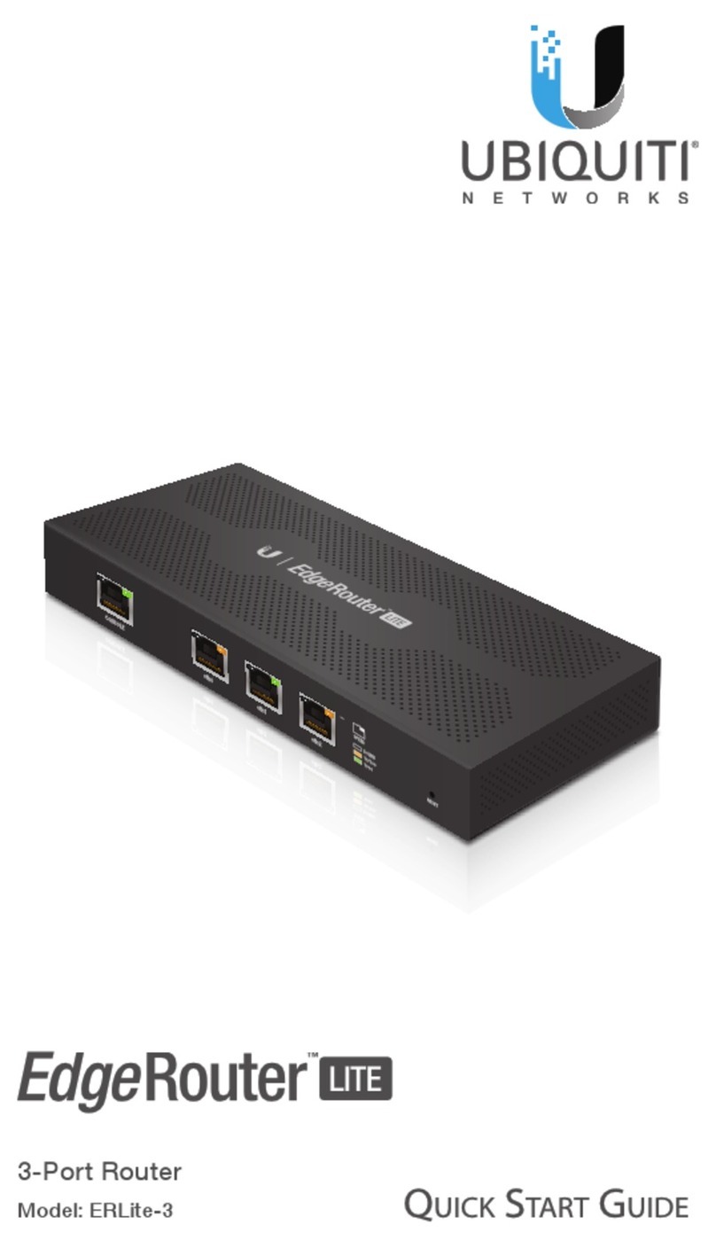
Ubiquiti ERLite-3 User manual

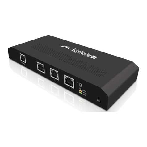
3-Port Router

i
Table of ContentsEdgeRouter™LiteUser Guide
Ubiquiti Networks, Inc.
Table of Contents
Chapter 1: Overview................................................1
Introduction. . . . . . . . . . . . .. . . . . . . . . . . . . . . . . . . . . . . .. . . . . . . . . . . . .. . . . . . . . . . .. . . . . . . . .1
PackageContents................................................................1
ConfigurationInterface System Requirements. . . . . . . . . . . . .. . . . . . . . . . . . . . . . . . . . . . . .1
HardwareOverview..............................................................1
Chapter 2: Installation . .. .. . .. . .. . .. . . . . .. .. . .. . .. . .. . .. . .. .. . .. . .. .2
Introduction. . . . . . . . . . . . .. . . . . . . . . . . . . . . . . . . . . . . . . . . . . . . . . . . . .. . . . . . . . . . . . . . . . . . . .2
InstallationoftheEdgeRouterLite................................................2
TypicalDeploymentScenarios....................................................3
Chapter 3: Using EdgeOS .. . .. .. . .. . .. . . . . .. . .. .. . .. . .. . .. . .. . .. .. . .5
Ports and StatusInformation. . . . . . . . . . . . .. . . . . . . . . . . . . . . . . . . . . . . .. . . . . . . . . . . . . . . . .5
Navigation.......................................................................5
CommonInterfaceOptions.......................................................6
Chapter 4: Dashboard Tab . .. .. . .. . .. . .. . .. . .. .. . .. . .. . .. . . . . .. .. . .10
Services.........................................................................10
Interfaces.......................................................................11
Chapter 5: Routing Tab . .. . .. . .. .. . .. . . . . .. . .. . .. .. . .. . .. . .. . .. . .. . 13
IPv6Routing....................................................................13
Routes..........................................................................14
OSPF............................................................................16
Chapter 6: Security Tab . . .. . .. . .. .. . .. . .. . .. . .. .. . .. . . . . .. . .. . .. .. . 19
FirewallPolicies.................................................................19
FirewallGroups..................................................................23
NAT.............................................................................24
VPN.............................................................................27
Chapter 7: ServicesTab . .. .. . .. . .. . .. . . . . .. .. . .. . .. . .. . .. . .. .. . .. . 28
DHCPServer ....................................................................28
DNS.............................................................................31
PPPoE...........................................................................32
Chapter 8: Users Tab . .. .. . .. . .. . .. . . . . .. .. . .. . .. . .. . .. . .. .. . .. . .. . 33
Local............................................................................33
Remote.........................................................................34
ii
Table of ContentsEdgeRouter™LiteUser Guide
Ubiquiti Networks, Inc.
Chapter 9: Toolbox................................................35
Ping.............................................................................35
Trace............................................................................36
Discover. . . . . . . . . . . . .. . . . . . . . . . . . . . . . . . . . . . . .. . . . . . . . . . . . . . . . . . . . . . . .. . . . . . . . . . . .36
PacketCapture..................................................................36
LogMonitor.....................................................................37
AppendixA: Command LineInterface . .. . . . .. . .. . .. . .. . .. .. . .. . .. . 38
Overview........................................................................38
AccesstheCLI...................................................................38
CLIModes.......................................................................40
AppendixB: Specifications . .. .. . .. . .. . .. . .. . .. .. . .. . .. . .. . .. . .. .. .47
AppendixC: Safety Notices. . .. . .. . .. .. . .. . . . . .. . .. . .. .. . .. . .. . .. . . 49
ElectricalSafetyInformation.....................................................49
AppendixD: Warranty.............................................50
GeneralWarranty................................................................50
AppendixE: Compliance Information. . .. . . . . .. . .. .. . .. . .. . .. . .. . .. 51
FCC.............................................................................51
IndustryCanada.................................................................51
AustraliaandNewZealand......................................................51
JapanVCCI-A....................................................................51
CEMarking......................................................................51
RoHS/WEEEComplianceStatement..............................................51
AppendixF:Declaration ofConformity . .. .. . .. . .. . .. . . . . .. .. . .. . ..53
AppendixG: Contact Information.. . .. . .. . .. . . . .. . .. . .. . .. . .. .. . .. . 54
UbiquitiNetworksSupport......................................................54
1
Chapter 1: OverviewEdgeRouter™LiteUser Guide
Ubiquiti Networks, Inc.
Hardware Overview
Back Panel
 

Power
GroundingHolewith
GroundingScrew
VentilationHoles
Front Panel Ports
   

Console ResetEthernet (0-2)
Interface Description
Console
RJ45serialconsole portfor CommandLineInterface
(CLI) management. Usea RJ45-to-DB9,serial console
cable,also knownas arollovercable, to connect the
Console porttoyourcomputer.(Ifyour computer
doesnot havea DB9port, thenyouwillalsoneeda
DB9adapter.)
Ethernet (0-2) 10/100/1000 MbpsEthernet ports.
Reset
To reset tofactory defaults, disconnect the Power
Adapter fromthePower port. Press and holdthe
Reset button while connectingthe Power Adapter
tothe Powerport. Keepholdingthebutton untilthe
right LEDon port 2 startsflashingandthen stops
aftera fewseconds.
Front Panel LEDs
The LEDs on theleftsideof eachport are not used atthis
time. Below is a description of the right LED functionality:
   

Power Speed/Link/Act
10/100 Mbps
Speed/Link/Act
1000Mbps
LED State Status
Console
Power Off EdgeRouterLitenot powered on.
Green EdgeRouterLiteis poweredon.
Ethernet (0-2)
Speed/
Link/Act
Off No Link
Amber Link Establishedat 10/100 Mbps
Amber Flashing Link Activity at10/100 Mbps
Green Link Establishedat 1000 Mbps
Green Flashing Link Activity at 1000Mbps
Chapter 1: Overview
Introduction
Thank you forpurchasing theUbiquitiNetworks™
EdgeRouter™Lite, model ERLite-3. It is part ofthe
EdgeMAX™platform. For more information, visit
www.ubnt.com/edgemax
The EdgeRouteris a router that provides a variety of
features, including routing, security,VirtualPrivate
Networking (VPN), monitoringandmanagement
services, and Quality of Service (QoS). For moredetailed
specifications, referto “EdgeOS” on page48.
This User Guideis designedto provide instructions about
installationof theEdgeRouterandto provide details about
howtousethe EdgeOS™Configuration Interface.
Configuration
The intuitive interface allows you to convenientlymanage
yourEdgeRouter using yourwebbrowser. (See “Using
EdgeOS” on page 5 for more information.) If youneed
toconfigureadvanced features orprefer configuration by
command line, you can use the Command Line Interface
(CLI). (See“Command Line Interface” on page 38 for
moreinformation.)
Package Contents
EdgeRouter Lite
EdgeRouter Lite Power Adapter
(12V, 1A) Power Cord
3-PortRouter
Model: E RLi te- 3
M2.9x20Screws
(Qty. 2) M2.9 Anchors
(Qty. 2) QuickStart Guide
Configuration Interface System
Requirements
• Microsoft WindowsXP, Windows Vista, Windows 7,
Windows 8, Linux, or Mac OS X
• Web Browser: GoogleChrome, MozillaFirefox, or
Microsoft InternetExplorer 8(or above)
2
Chapter 2: InstallationEdgeRouter™LiteUser Guide
Ubiquiti Networks, Inc.
Chapter 2: Installation
Introduction
This chapter coversthe installationinstructionsanda
couple of typicaldeployment scenarios (see “Typical
Deployment Scenarios” on page 3). After you
install theEdgeRouter, refer to the instructions in “Using
EdgeOS” on page 5, which explain howtoaccess the
ConfigurationInterface.
Installation of the EdgeRouter Lite
Mount theEdgeRouter ona wall, or placeit on a
Note: Keep 20 mm of clearance next to the
ventilationholesforadequate airflow.
Cabling Requirements
• For indoor applications, use Category 5 (or above)
cabling approvedfor indoor use.
• For outdoor applications, shielded Category 5 (or
above) cabling should be used forallwired Ethernet
connections andshouldbe grounded through the
ACground of the power supply.We recommendthat
youprotect youroutdoor networksfrom themost
brutal environmentsand devastatingESD attacks with
industrial-grade shielded Ethernet cable fromUbiquiti
Networks™. For more details, visit:
www.ubnt.com/toughcable
Note: Althoughthe cabling canbe located
outdoors, the EdgeRouter Liteitself should be
housed inside a protective enclosure.
Terms of Use
All Ethernet cabling runs must use CAT5(or above).It
is the customer’s responsibility tofollow local country
regulations, including operation withinlegal frequency
channels, output power, indoor cabling requirements, and
Dynamic Frequency Selection(DFS)requirements.
Wall-Mounting
To mount the EdgeRouter Lite on awall you willneed a
drill, a 6 mm drillbit, and a Phillipsscrewdriver.
1. Use a 6mm drill bit todrill twoholes 100 mmapart.
(You canusethetemplateatthe bottomof the page to
mark the holes.)
2. Insert theM2.9Anchors into theholes. Use a Phillips
screwdriver tosecurea M2.9x20Screw toeachanchor.
Leavea clearance of approximately 3mm between
eachscrew head and its anchor.
3mm
Note: Youcan alsomount theEdgeRouter Litein a
verticalorientation.
3. Position theEdgeRouter Litewith theEthernet
ports facing down. Place the Wall-MountSlots of the
EdgeRouter Lite over the screw heads on thewall.Then
slidethe EdgeRouter Lite down tolock itinto place.
Mounting Template
Therecommended mounting orientation is horizontal withthe ports facing down.
Note:TheEdgeRouterLitecan alsobe mounted ina vertical orientation.Turnthis page sidewaysto mark theholes for
verticalplacement.
100mm
3
Chapter 2: InstallationEdgeRouter™LiteUser Guide
Ubiquiti Networks, Inc.
Grounding the EdgeRouter Lite (Optional)
TheEdgeRouterLiteisgrounded through thePower
Adapter; however, youcan add optional ESD grounding for
enhanced ESD protection.
1. Loosen theGrounding Screw tosecure a ground wire
(not included) tothe Grounding Hole.
2. Secure theotherend of the ground wire toa
grounding block.
Connecting Power
1. Connect thePowerAdapter tothePower port.
2. Connect thePowerCord tothePowerAdapter. Connect
theother endof the PowerCord
Typical Deployment Scenarios
While there arenumerousscenariosthatarepossible, this
section highlights a coupleof typicaldeployments:
• Service ProviderDeployment
• CorporateDeployment
Service Provider Deployment
This scenario uses sixEdgeRouter devices:
1. OSPFArea 0 to OSPF Area 1
2. OSPFArea 0 to OSPF Area 2
3. OSPFArea 1
4. OSPFArea 1 to Internet
5. OSPFArea 2
6. OSPFArea 2 to Internet
Site-to-Site
Link
OSPF
Area0
OSPF
Area1
OSPF
Area2
Internet
Internet
SiteA
SiteB
Herearethetypical steps tofollow:
1. Configure theappropriatesettingson theSystem tab
(see “System” on page6 for more information):
• HostName
• TimeZone
• Gateway
• NameServer
• DomainName
• NTP
2. Configure theinterfaces onthe Dashboard tab; see
“Interfaces” on page11 for more information.
3. Configure OSPFsettingsonthe Routing > OSPFtab; see
“OSPF” on page 16 for moreinformation.
4
Chapter 2: InstallationEdgeRouter™LiteUser Guide
Ubiquiti Networks, Inc.
4. Configure DHCPserver(s)on theServices tab; see
”DHCP Server” on page 28 for more information.
5. Configure NATrulesonthe Security >NAT tab; see
”NAT” on page24 for more information.
6. Configure firewall rules on the Security> Firewall
Policies tab; see ”FirewallPolicies” on page 19 for
moreinformation.
7. Configure additional settings as neededfor your
network.
Corporate Deployment
This scenario uses a single EdgeRouter device. The three
independent interfaces connectto thefollowing:
• Internet
• DMZ
• LAN
Internet
DMZ
LAN
FirewallPolicies
Herearethetypical steps tofollow:
1. Configure theappropriatesettingson theSystem tab
(see “System” on page6 for more information):
• HostName
• TimeZone
• Gateway
• NameServer
• DomainName
• NTP
2. Configure theinterfaces onthe Dashboard tab; see
“Interfaces” on page11 for more information.
3. Configure DHCPserver(s)on theServices tab; see
”DHCP Server” on page 28 for more information.
4. Configure NATrulesonthe Security >NAT tab; see
”NAT” on page24 for more information.
5. Configure firewall rules on the Security> Firewall
Policies tab; see ”FirewallPolicies” on page 19 for
moreinformation.
6. Configure additional settings as neededfor your
network.
5
Chapter 3: Using EdgeOSEdgeRouter™LiteUser Guide
Ubiquiti Networks, Inc.
Chapter 3: Using EdgeOS
EdgeOS is a powerful, sophisticatedoperatingsystemthat
manages your EdgeRouter. It offers both a browser-based
interface (EdgeOSConfigurationInterface) foreasy
configuration and a Command Line Interface (CLI)for
advanced configuration.
To accesstheEdgeOSConfiguration Interface:
1. Connect anEthernetcablefrom theEthernetport
of your computer to theportlabeled 0on the
EdgeRouter.
2. Configure the Ethernetadapter onyour computer
witha static IPaddresson the192.168.1.x subnet (e.g.,
192.168.1.100).
Note: As an alternative, youcan connect a serial
cable totheConsole port of the EdgeRouter. See
“Command Line Interface” on page 38 for
moreinformation.
3. Launch your web browser. Type https://192.168.1.1 in
theaddress field. Press enter (PC)or return (Mac).
4. The login screen willappear. Enter ubnt inthe
Username and Password fields. Read theUbiquiti
License Agreement, and check the box next to Iagree
tothetermsofthisLicenseAgreement toacceptit. Click
Login.
The EdgeOS ConfigurationInterface will appear, allowing
youto customizeyour settingsas needed.
Note: To enhance security, we recommendthatyou
changethedefaultlogin using at leastone of the
followingoptions:
• Set up a newuser account on the Users>Local tab
(preferred option). Fordetails, goto “AddUser”
on page 33.
• Changethe default password of the ubntlogin on
theUsers> Local tab. For details, goto “Configure
the User” onpage34.
Ports and Status Information
ThePorts imagedisplays the activeconnections. An amber
port indicates 10/100 Mbps, and a greenport indicates
1000 Mbps. TheStatus bar graphs display thefollowing:
CPU Thepercentageof processingpowerthat the
EdgeRouteris using isdisplayed.
RAM The percentage of RAM that the EdgeRouter is using
isdisplayed.
Uptime The duration of theEdgeRouter’s activity is
displayed.
Place your mouse over aportto viewthe following:
Enabled/Disabled Theadministrativestatus is displayed.
Link The connection status isdisplayed.
Speed Thespeed (in Mbps) and duplex modeare
displayed.
Navigation
The EdgeOS softwareconsists of five primary tabs, and
some ofthesetabshave sub-tabs. ThisUser Guidecovers
eachtab witha chapter. For details on a specific tab, refer
totheappropriatechapter.
• Dashboard The“Dashboard Tab” onpage 10
displays status information about services and
interfaces. You can also configure interfacesandVirtual
LocalAreaNetworks(VLANs).
• Routing The“Routing Tab” on page 13 configures
staticroutesand Open Shortest Path First(OSPF)
settings, includingmetrics, areas, and interfaces.
• Security The“Security Tab” on page 19 configures
firewall policies, firewall groups, NetworkAddress
Translation (NAT) rules, and PPTP VPNoptions.
• Services The“Services Tab” on page 28 configures
DHCP servers, DNSforwarding, and the PPPoE server.
• Users The“Users Tab” on page 33 configures user
accounts withadministratoror operatoraccess.
6
Chapter 3: Using EdgeOSEdgeRouter™LiteUser Guide
Ubiquiti Networks, Inc.
Dependingon thetabyou click, some of thescreens
display information and optionsin multiple sections. You
can click theopen/close tab to hide ordisplaya section.
Open/CloseTab
Open/CloseTab
Common Interface Options
Thecommon interface optionsare accessiblefrom all tabs
onthe EdgeOS interface:
• Welcome
• CLI
• Toolbox
• Alerts
• System
Required fields aremarked bya blue asterisk *. Whenthe
information icon isdisplayed, you canclickthe icon for
moreinformationaboutanoption.
Welcome
At the top left of thescreen, click Welcome toview the
Logout option:
Logout To manually log out of the EdgeRouter
ConfigurationInterface, click this option.
CLI
Advanced userscan make configurationchanges using
Linux commands. At thetop right of the screen,click the
CLI button. See “Command Line Interface” on page
38 for moreinformation.
Toolbox
At the top right ofthe screen, click theToolbox
button. The followingnetworkadministrationand
monitoringtools areavailable:
• “Ping” on page 35
• “Trace” on page 36
• “Discover” on page36
• “Packet Capture” on page 36
• “Log Monitor” on page37
Alerts
The numberof new alerts is displayedin a redpopup.
At thebottom of thescreen, click theAlerts tab.
A table displays the followinginformation about each
important event.
Message A description of theevent is displayed.
Field The settings that are affected by theeventare
displayed.
Actions Thefollowing optionsareavailable:
• Remove Clickthisbutton toclear an alert.
• Clear All Click this button toclear all alerts.
Click the top right corner of theAlerts tab to close it.
System
At thebottom of thescreen, click theSystem tab toaccess
thedevice settings.
Thedevicesettingsare organized intothese sections:
• “Basic Settings” on page 7
• “Management Settings” on page7
• “Configuration Management & Device Maintenance”
on page 8
• “Restart &Shut Down Router” on page 9
7
Chapter 3: Using EdgeOSEdgeRouter™LiteUser Guide
Ubiquiti Networks, Inc.
Basic Settings
HostName
System host name Enter a name forthe EdgeRouter. The
host name identifies the EdgeRouter asa specificdevice.
For example, a .com URL typically uses this format:
<host_name>.domain_name.com
Time Zone
UseCoordinated Universal Time (UTC) UTCis the
international time standard used by NetworkTime
Protocol (NTP) servers. If your routers arelocated in
multiple timezones, then you may wantto use UTC.
Timezone To set yournetworkto a specific timezone,
select Timezone and configure thefollowing:
• Selectcontinent/ocean Select yourlocation.
• Selectcountry/region Select yourlocation.
• Selecttime zone Select yourtimezone.
Gateway
System gateway address Enter the IP address of your
gateway. This willset up your default route. If you want to
set up additional default routes, configure them as static
routesontheRouting tab. See “Routing Tab” on page
13 for moreinformation.
Name Server
Domain NameSystem (DNS) translates domainnamesto
IP addresses; each DNS server on the Internetholds these
mappingsin itsrespectiveDNSdatabase.
System name server Enter the IP address of yourDNS
server (example: 192.0.2.1 for IPv4 or2001:db8::1 for IPv6).
Click Add New toaddadditional servers.
Domain Name
System domain name Enter thedomain name of your
EdgeRouter. The domain nameidentifies theEdgeRouter’s
network on the Internet. For example, a .com URL typically
uses this format:
host_name.<domain_name>.com
NTP
NTP is a protocol for synchronizing the clocks ofcomputer
systems overpacket-switched, variable-latency data
networks. Youcan use itto set thesystemtimeon the
EdgeRouter. If theSystemLog optionis enabled, then
thesystemtimeis reported nextto every log entry that
registers a systemevent.
Automatically update system time using NTP By
default, theEdgeRouterobtains the systemtime froma
timeserver ontheInternet.
Click Savetoapply your changes.
ManagementSettings
SSH Server
Enable Enabled by default.This option allows SSH
(Secure Shell) access tothe EdgeRouter for remote
configuration bycommand line. SSHuses encryption and
authentication, so it is a secure form of communication.
See “Command Line Interface” on page 38 for more
information.
Port Specify the TCP/IP portof theSSHserver. The default
is22.
8
Chapter 3: Using EdgeOSEdgeRouter™LiteUser Guide
Ubiquiti Networks, Inc.
TelnetServer
Enable Disabledby default. Thisoptionallows Telnet
access to the EdgeRouter for remote configuration
by command line. Telnetis not a secure form of
communication, so werecommend SSH. See “Command
Line Interface” on page 38 for moreinformation.
Port Specify the TCP/IP portof theTelnet server. The
defaultis 23.
SystemLog
Every loggedmessagecontains at least a system time and
host name. Usuallya specific service namethat generates
thesystemeventis alsospecifiedwithin themessage.
Messages fromdifferentservices have different contexts
and different levelsof detail. Usually error, warning, or
informationalsystem servicemessages arereported;
however, moredetailed debug levelmessages can also
be reported.The more detailed thesystemmessages
reported, thegreater the volume of log messages
generated.
Log toremoteserver This option allows the EdgeRouter
tosendsystem log messages to a remote server. Enter
theremotehostIP address and TCP/IP port thatshould
receive thesystem log(syslog)messages. 514 is the
defaultport forthe commonly used, system message
logging utilities.
Note: Properly configure theremotehost toreceive
syslog protocol messages.
SNMPAgent
SimpleNetwork Monitor Protocol (SNMP) is an
application layerprotocolthat facilitatestheexchange
of management information between network
devices. Network administrators use SNMP to monitor
network-attacheddevicesfor issues that warrant
attention.
The EdgeRouter contains an SNMP agent, which does the
following:
• Provides aninterfacefor device monitoring using SNMP
• CommunicateswithSNMP management applications
for network provisioning
• Allowsnetwork administrators tomonitornetwork
performanceand troubleshoot network problems
For the purpose of equipment identification, configure the
SNMP agent with contact and location information:
Enable Disabledby default. Thisoptionactivatesthe
SNMP agent.
SNMPcommunity Specify theSNMPcommunitystring.
Itis required to authenticate access to MIB(Management
Information Base) objectsand functionsas anembedded
password. Thedevice supports a read-only community
string; authorized management stations have read access
toallthe objects in theMIB except thecommunity strings,
but donot have write access.The device supports SNMP
v1. The default ispublic.
Contact Specify the contact who should be notifiedin
case of emergency.
Location Specify thephysical location of the EdgeRouter.
Click Savetoapply your changes.
Configuration Management &Device
Maintenance
Thecontrolsinthissectionmanagethe device
configuration routines andfirmwaremaintenance.
Back Up Config
We recommendthat you back up your current system
configuration beforeupdating thefirmware oruploading
a new configuration.
Downloadbackup config file Click Download to
download thecurrentsystem configuration file.
Note: Westrongly recommendthat you save the
configuration filein asecurelocation because it
includes confidential information. The user login
passwords areencrypted; however, other passwords
and keys (such as those used for VPN, BGP,
authentication, and RADIUS) arestored in plain text.
9
Chapter 3: Using EdgeOSEdgeRouter™LiteUser Guide
Ubiquiti Networks, Inc.
Restore Config
Upload config file Click Uploadafile to locate the
new configuration file. Select the file and click Choose.
We recommendthat you back up your current system
configuration beforeuploadingthe newconfiguration.
Upgrade System Image
Download the firmwarefilefrom downloads.ubnt.com
and saveit onyour computer.
The firmware update iscompatible withall configuration
settings. Thesystem configurationis preserved while
theEdgeRouter isupdatedwith anew firmware version.
However, we recommend that youback up yourcurrent
system configurationbefore updatingthe firmware.
Upload system image To update the EdgeRouter with
new firmware, click Uploadafile and locate thenew
firmware file. Then click Choose.
Please bepatient, asthe firmwareupdate routinecantake
threeto seven minutes.You cannot access the EdgeRouter
until thefirmware updateroutineiscompleted.
WARNING: Do not power off, do not reboot, and
do not disconnect the EdgeRouter fromthe power
supply during the firmwareupdateprocessas these
actionswill damagethe EdgeRouter!
Restart & ShutDown Router
RestartRouter
Restart To turntheEdgeRouter off andbackon again,
click this option.
Shut Down Router
Shut Down To turnoffthe EdgeRouter,click thisoption.
WARNING: ClickShut Down to properly shutdown
theEdgeRouter. An improper shutdown, such
asdisconnecting the EdgeRouter from its power
supply, runs the risk of data corruption!
Click the top right corner of theSystem tab toclose it.
10
Chapter 4: DashboardTabEdgeRouter™LiteUser Guide
Ubiquiti Networks, Inc.
Chapter 4: Dashboard Tab
TheDashboard tab displays status information about
services and interfaces. You canalso configureinterfaces
and Virtual Local Area Networks (VLANs). Any setting
marked with a blueasterisk*isrequired.
Services
Status informationis displayed. Eachheading is a
convenientlink to the appropriatetab.
Routes
Thefollowing routetypes are listed:
• Connected
• Static
• RIP (Routing Information Protocol)
• OSPF(Open Shortest Path First)
• EBGP (Exterior Border Gateway Protocol)
• IBGP (Interior Border Gateway Protocol)
The numberof each route type and the totalnumber of
routes aredisplayed. Click Routes todisplay theRouting
>Routes tab. Goto“Routes” on page 14 for more
information.
OSPF
The OSPF status, settings, andnumber of areas are
displayed. Click OSPF todisplay theRouting> OSPF tab.
Go to“OSPF” on page 16 for moreinformation.
NAT
The NAT (NetworkAddress Translation) statusandnumber
of NAT rules aredisplayed. ClickNAT to display the
Security >NAT tab. Go to “NAT” on page24 for more
information.
Firewall
Thefirewall status and numbersof sets and rules are
displayed. Click Firewall todisplay theSecurity >Firewall
Policies tab. Go to “FirewallPolicies” on page 19 for
moreinformation.
11
Chapter 4: DashboardTabEdgeRouter™LiteUser Guide
Ubiquiti Networks, Inc.
DHCP
The DHCP server status and numbersof active and
inactive servers are displayed. Click DHCP todisplay the
Services tab. Goto “DHCP Server” on page28 for more
information.
Interfaces
Distribution
Click Hide Distributionto hidethe Interfaces>Distribution
section. Clickthe remaining open/close tab todisplay the
Interfaces >Distributionsection again.
Open/CloseTab
TheRXRateand TXRate graph displays the current data
trafficin both graphicaland numerical form.The graph
scale and throughput dimension (Mbps, for example)
changedynamically depending onthe meanthroughput
value. The statistics areupdated automatically.
TheRX and TX piecharts display the data traffic allocated
among theports of theEdgeRouter. The pie charts are
updatedautomatically.
Place your mouse over aport’sportion ofthe pie chart to
view its percentage of data traffic allocation, TX (amount
of transmitteddata),and RX (amountof received data).
All/Ethernet/VLAN
AddVLAN To createa new VLAN, click AddVLAN.
TheCreatea NewVLAN screen appears.
• VLANID TheVLAN IDis aunique value assigned to
eachVLAN at a single device; every VLAN IDrepresents
a different VLAN. The VLAN ID range is 2 to 4094.
• Interface Select the appropriate interface.
• Description Enter keywordsto describe thisVLAN.
• MTU Enter the MTU (Maximum Transmission Unit)
value, which is themaximumpacketsize(in bytes)thata
network interface can transmit. The default is 1500.
• Address Select one of the following:
- Noaddresssettings The VLAN uses no address
settings. (In most cases, an address is needed.)
- UseDHCP The VLAN acquires network settings from
a DHCPv4 server.
- UseDHCP for IPv6 The VLAN acquires network
settings froma DHCPv6 server.
- Manually define IP address(es) Enter the
staticIP address (example: 192.0.2.1/24 for IPv4
or 2001:db8::1/32 for IPv6). ClickAdd IP to enter
additional IPaddresses.
ClickSave toapply your changes, or click Cancel.
Search Allows youto search for specific text. Begin
typing; thereis no need to press enter. The results are
filtered in real timeas soon as you type two ormore
characters.
All/Ethernet/VLAN Clickthe appropriate tab tofilterthe
interfaces asneeded.
• All All interfaces aredisplayed by default.
• Ethernet All of theEthernet interfaces aredisplayed.
• VLAN All VLANs aredisplayed.
12
Chapter 4: DashboardTabEdgeRouter™LiteUser Guide
Ubiquiti Networks, Inc.
A table displays the followinginformation about each
interface. Click a columnheading to sort by that heading.
Description Thekeywords youentered todescribethe
interfacearedisplayed.
Interface Thename of the interfaceisdisplayed.
Type Thetype of interfaceis displayed.
IP Addr TheIP address of theinterface is displayed.
MTU TheMTU (Maximum TransmissionUnit) value of the
interface is displayed. This is themaximum packetsize (in
bytes)thatthe interfacecan transmit.
TX The transmit speed of theinterfaceis displayed.
RX The receive speed of the interfaceis displayed.
Status The connection status of the interfaceis displayed.
Actions Click theActions buttonto accessthefollowing
options:
• Config To configuretheinterface,click Config. Go to
theConfiguretheInterfacesection.
• Disable Disablethe interface while keeping its
configuration.
Configure the Interface
After youclick Config, the InterfaceConfiguration screen
appears.
Makechangesasneeded.
• Description Enter keywordsto describe thisinterface.
• Enable Check thebox toenable theinterface. All of
theinterfacesaresavedin thesystem configurationfile;
however, only theenabled interfaces are active on the
device.
• Address Select one of the following:
- Noaddresssettings Theinterfaceuses no address
settings. (In most cases, an address is needed.)
- UseDHCP Theinterfaceacquiresnetworksettings
from a DHCPv4 server. Click the Renew button to
acquire fresh network settings.
- UseDHCP for IPv6 Theinterfaceacquiresnetwork
settings froma DHCPv6 server.
- Manually define IP address(es) Enter the
staticIP address (example: 192.0.2.1/24 for IPv4
or 2001:db8::1/32 for IPv6). ClickAdd IP to enter
additional IPaddresses.
• MTU Enter the MTU (Maximum Transmission Unit)
value, which is themaximumpacketsize(in bytes)thata
network interface can transmit. The default is 1500.
• Speed/Duplex Thedefaultis Auto negotiation. The
EdgeRouter automatically negotiates transmission
parameters, such as speedand duplex, with its
counterpart. Inthis process, the networkeddevices
first sharetheircapabilitiesand thenchoose thefastest
transmission modetheybothsupoprt.
To manually specify the transmission linkspeed and
duplex mode, select one of thefollowing options:
100/full, 100/half, 10/full, or 10/half.
Full-duplex mode allows communication in both
directionssimultaneously. Half-duplexmode
allows communication in both directions, butnot
simultaneously and only inone direction at a time.
• Proxy ARP Enable theEdgeRouter toanswer a source
host’s ARP (Address ResolutionProtocol) requests for
theIP address of adestinationhost thatis not located
onthe source host’s network. ARP allows hosts on the
samenetworkto discovereach other’s IP address via a
layer 2 broadcastto all MAC addresses. If they arenot on
thesame network, the layer2 broadcast willnot reach
its destination; however, the EdgeRouter can serve as
thego-between ifProxyARP isenabled.
ClickSave toapply your changes, or click Cancel.
13
Chapter 5: Routing TabEdgeRouter™Lite User Guide
Ubiquiti Networks, Inc.
Chapter 5: Routing Tab
TheRouting tab displays status information about a variety
of connected, static, RIP, and OSPFroutes. You canalso
configurestatic routes andOSPF options. Any setting
marked with a blueasterisk*isrequired.
Youhavetwosub-tabs:
Routes View route informationand create staticroutes.
OSPF Configure OSPFoptions.
IPv6 Routing
IPv6 (Internet Protocol version6) is gaining popularity
and is bound togrow as IPaddressingdemandsincrease.
The EdgeOS ConfigurationInterface supports IPv6 forthe
followingoptions:
• System >NameServer configuration
(Refer to“Name Server” on page 7.)
• Dashboard >VLAN configuration
(Refer to“Add VLAN” on page 11.)
• Dashboard >Interface configuration
(Refer to“Configure the Interface” on page12.)
For IPv6 addresses, theEdgeOS Configuration Interface
supports “::” (double-colon) notation, which substitutes
“::” fora contiguous sequence of16-bit blocks setto zero.
Hereis an example: 2001:db8::1
If written out, the IPv6 address becomes:
2001:db8:0000:0000:0000:0000:0000:0001
TheEdgeOS ConfigurationInterfacedisplays IPv6
addresses only in two locations:
• System >NameServer section
• Dashboard tab
TheEdgeOS ConfigurationInterfacewill increase its
supportof IPv6 infuture releases. For otheroptions, you
can usethe CLI, which has comprehensive IPv6support.
Note: Use the CLIto viewIPv6 optionsconfigured
in theCLIbut not supported by the EdgeOS
ConfigurationInterface.
14
Chapter 5: Routing TabEdgeRouter™Lite User Guide
Ubiquiti Networks, Inc.
Routes
A routedetermines how traffic travelsto its destination
network. If more than one routeis suitable, the
EdgeRouter uses administrative distance as a metricto
compareall available routes, includingdirectlyconnected
routes, manually configuredstaticroutes, dynamic routes,
and the default route. The EdgeRouter uses theroutewith
thelowest administrativedistance.
All/Static/Connected/RIP/OSPF
Add Static Route To create a newstatic route, clickAdd
Static Route.
TheCreateStaticRoutescreenappears.
Complete thefollowing:
• SelectRoute Type Youhavethree options: Gateway,
Interface, or BlackHole.
- Gateway Define a route usingthe IP address and
subnet mask of thenext hopgateway.
• Destination network Enter theIPaddress and
subnetmask using slash notation:
<network_IP_address>/<subnet_mask_number>
(example: 192.0.2.0/24).
Thefirst default routeis configuredon the System
tab; see “System gateway address” on page7
for more information.To createmultiple default
routes, set up staticroutes and enter 0.0.0.0/0.
• Nexthopaddress Enter theIP address.
• Distance (1-255) Enter theadministrative distance.
If thereare identical routes fromdifferent sources
(such as static, RIP, or OSPF), the EdgeRouter
comparestheroutes and uses theroutewith the
lowestdistance.
• Enable Check the box toenable the route.
Click Save toapply your changes.
- Interface Define a route usinga next hop interface.
• Destination network Enter theIPaddress and
subnetmask using slash notation:
<network_IP_address>/<subnet_mask_number>
(example: 192.0.2.0/24).
• Nexthopinterface Select the appropriate
interface from thedrop-downlist.
• Distance (1-255) Enter theadministrative distance.
If thereare identical routes fromdifferent sources
(such as static, RIP, and OSPF), theEdgeRouter
comparestheroutes and uses theroutewith the
lowestdistance.
• Enable Check the box toenable the route.
Click Save toapply your changes.
- Black Hole Define a route that drops unwanted
traffic.
• Destination network Enter theIPaddress and
subnetmask using slash notation:
<network_IP_address>/<subnet_mask_number>
(example: 192.0.2.0/24).
• Distance (1-255) Enter theadministrative distance.
If thereare identical routes fromdifferent sources
(such as static, RIP, and OSPF), theEdgeRouter
comparestheroutes and uses theroutewith the
lowestdistance.
• Enable Check the box toenable the route.
Click Save toapply your changes.
Search Allows youto search for specific text. Begin
typing; thereis no need to press enter. The resultsare
filtered in real timeas soon as you type two ormore
characters.
15
Chapter 5: Routing TabEdgeRouter™Lite User Guide
Ubiquiti Networks, Inc.
All/Static/Connected/RIP/OSPF Clickthe appropriate tab
tofilterthe routes asneeded.
• All All routes aredisplayed by default.
• Static All staticroutes that you haveconfiguredare
displayed.
• Connected All routes that are directlyconnected tothe
EdgeRouteraredisplayed.
• RIP All RIP (Routing Information Protocol) routes are
displayed. RIP isan interior, distance vector routing
protocol that uses hop count as a metricto determine
thebest route.
• OSPF All OSPF (Open ShortestPath First)routesare
displayed. OSPF is aninterior, link-state routingprotocol
that uses costas a metrictodeterminethe bestroute.
The bandwidth of an interface determines thecost – the
higherthe bandwidth, thelower the cost.
A table displays the followinginformation about each
route. Clicka column heading tosort by that heading.
Selected Thestatus of the route, whether it has been
selected forthe routingtable, is displayed.
Destination Thedestination IP address isdisplayed.
NextHop TheIP address of thenext-hop interface is
displayed.
Interface Thename of the interfaceisdisplayed.
Route Type The type of routeis displayed.
In FIB The forwardingstatus of the route, whether it is in
theFIB (Forwarding Information Base), isdisplayed.
Actions Click the Actions buttonto accessthefollowing
options:
• Config To configurethe route, click Config. Go tothe
ConfiguretheStaticRoutesectionbelow.
• Delete Delete theroute; itsconfiguration will be
removed.
• Disable Disablethe route whilekeeping its
configuration. (Thisoption is not availablefor black hole
routes.)
Configure the StaticRoute
After youclick Config, the StaticRouteConfiguration screen
appears.
Followthe instructionsfor your routetype:
Gateway
• Route type The gateway route uses theIP address and
subnet mask of thenext hopgateway.
• Destination network TheIP address andsubnet mask
are displayed inslash notation.
• Nexthopaddress TheIP address of thenext hop
gateway isdisplayed.
• Distance (1-255) Enter the administrative distance. If
thereare identical routes from different sources (such
asstatic, RIP, andOSPF), theEdgeRouter comparesthe
routesand uses the route withthe lowest distance.
• Enable Check the box toenable the route.
ClickSave toapply your changes.
Interface
• Route type The interfaceroute uses thenexthop
interface.
• Destination network TheIP address andsubnet mask
are displayed inslash notation.
• Nexthopinterface Thename of the nexthop interface
isdisplayed.
• Distance (1-255) Enter the administrative distance. If
thereare identical routes from different sources (such
asstatic, RIP, andOSPF), theEdgeRouter comparesthe
routesand uses the route withthe lowest distance.
• Enable Check the box toenable the route.
ClickSave toapply your changes.
16
Chapter 5: Routing TabEdgeRouter™Lite User Guide
Ubiquiti Networks, Inc.
BlackHole
• Route type The blackholeroutedrops unwantedtraffic.
• Destination network TheIP address andsubnet mask
are displayed inslash notation.
• Distance (1-255) Enter the administrative distance. If
thereare identical routes from different sources (such
asstatic, RIP, andOSPF), theEdgeRouter comparesthe
routesand uses the route withthe lowest distance.
• Enable Check the box toenable the route.
ClickSave toapply your changes.
OSPF
Using Link StateAdvertisements, routers communicate
witheach otherwhen there is a router orlink status
change.Each router maintains theinformationin a
database, which isused tocreate and update a network
map from therouter’s pointof view. Each router thenuses
themap tobuild and updatea routing table.
Router
Router ID Enter theIP address that identifies a specific
routerin an OSPF network. In OSPF, the highest RouterID
determines which router is theDesignatedRouter(DR),
which distributes updatestothe other OSPFrouters.
Click Save toapply your changes, or click DeleteOSPF
toremovethe Router, Redistribution, and Area settings
(Interfacessettings are retained).
Redistribution
A single router can use multiple routing protocols, such
asOSPF and RIP, which use incompatible metrics. It
must reconcileinformationfrom multiple protocols to
determine whichroute to use for a specific destination
network. You can changethe metrics of the distributed
protocol tocreate protocol compatibility.
Redistributeconnected If enabled, the EdgeRouter
connects an OSPFarea toa network using a different
routing protocol and redistributes theotherprotocol’s
directly connected routes into theOSPF area. These routes
become external OSPF routes.
- Metric If there are multiple routes tothe same
destination, OSPFuses themetricto select aroute
for theroutingtable. Assign a cost valueto the
redistributed connected routes. TheEdgeRoutercan
thenuse this metric to comparethese routes to other
OSPFroutes.
Redistributestatic If enabled, the EdgeRouter connects
an OSPFarea to a network using a different routing
protocol and redistributes the other protocol’s static
routesintothe OSPFarea.These routesbecomeexternal
OSPFroutes.
- Metric If there are multiple routes tothe same
destination, OSPFuses themetricto select aroute
for theroutingtable. Assign a cost valueto the
redistributed static routes. TheEdgeRoutercan then
use thismetricto comparetheseroutes tootherOSPF
routes.
Announcedefault route If enabled, the EdgeRouter
communicates the default route totheotherrouters of
theOSPF network, eliminatingthe need toconfigure
thedefault route onthe other routers. Thedefaultroute
connects the OSPF network to anoutsidenetwork.
17
Chapter 5: Routing TabEdgeRouter™Lite User Guide
Ubiquiti Networks, Inc.
Areas
To enhance scalability, an OSPF network is comprised of
smallersectionscalledareas.Atthe minimum, there isthe
backbone area, called Area 0.
AddArea To create a new area, clickAdd Area.
TheCreateOSPFAreascreenappears.
Complete thefollowing:
• Area ID This is thenumber that identifiesan area. It can
be an integer oruse aformat similar toanIPv4 address.
• Area Type This defines theroutes thatareacceptable
insidethe area. Selectthe appropriate option:
- Normal/sec Thedefaulttypeacceptsallroutes.
- NSSA A NSSA (Not So Stubby Area) network is a
variation of a stub network. It can importexternal
routes fromtype7 Link State Advertisements, which
are NSSA-specific.
- Stub The network has no external routes. Typically, it
hasa default route foroutbound traffic.
• Auth Type Authentication helps secure communication
between routers. Select theappropriate option:
- Off No authentication isused.
- MD5/sec Eachrouteruses a key (password) and key
ID. This is themost secure optionbecause the key is
nevertransmitted.
- Plain text Each router uses a key. This provides
minimal security because thekeyis transmitted in
plaintext format.
• Network Enter theIPaddress and subnet mask using
slashnotation:
<network_IP_address>/<subnet_mask_number>
(example: 192.0.2.0/24).
Click Add New toentermorenetworkaddresses.
ClickSave toapply your changes.
A table displays the followinginformation about each
OSPFArea. Click a columnheadingto sort by that
heading.
Area ID The identificationnumber ofthe area is
displayed.
Area Type The type of area is displayed.
Auth Type The authentication type of thearea is
displayed.
Network Thenetwork addressof the area is displayed.
Actions Click the Actions buttonto accessthefollowing
options:
• Config To configurethe OSPF Area, click Config. Go to
theConfiguretheOSPFArea section.
• Delete Delete theOSPFArea.
Configure the OSPF Area
After youclick Config, the OSPFArea Configuration screen
appears.
Makechangesasneeded.
• Area ID This is thenumber that identifiesan area. It can
be an integer oruse aformat similar toanIPv4 address.
• Area Type This defines theroutes thatareacceptable
insidethe area. Selectthe appropriate option:
- Normal/sec Thedefaulttypeacceptsallroutes.
- NSSA A NSSA (Not So Stubby Area) network is a
variation of a stub network. It can importexternal
routes fromtype7 Link State Advertisements, which
are NSSA-specific.
- Stub The network has no external routes. Typically, it
hasa default route foroutbound traffic.
• Auth Type Authentication helps secure communication
between routers. Select theappropriate option:
- Off No authentication isused.
- MD5/sec Eachrouteruses a key (password) and key
ID. This is themost secure optionbecause the key is
nevertransmitted.
- Plain text Eachrouteruses a key. This provides
minimal security because thekeyis transmitted in
plaintext format.

Other manuals for ERLite-3

3

Other Ubiquiti Network Router manuals

Ubiquiti LTU LR User manual

Ubiquiti

Ubiquiti LTU LR User manual

Ubiquiti EdgeRouter 6P User manual

Ubiquiti

Ubiquiti EdgeRouter 6P User manual

Ubiquiti EdgeRouter ER-8 User manual

Ubiquiti

Ubiquiti EdgeRouter ER-8 User manual

Ubiquiti ER-8-XG User manual

Ubiquiti

Ubiquiti ER-8-XG User manual

Ubiquiti LiteStation2 User manual

Ubiquiti

Ubiquiti LiteStation2 User manual

Ubiquiti UDM User manual

Ubiquiti

Ubiquiti UDM User manual

Ubiquiti airCube Instruction Manual

Ubiquiti

Ubiquiti airCube Instruction Manual

Ubiquiti UCK-G2 User manual

Ubiquiti

Ubiquiti UCK-G2 User manual

Ubiquiti ER-8-XG User manual

Ubiquiti

Ubiquiti ER-8-XG User manual

Ubiquiti UniFi AP PRO User manual

Ubiquiti

Ubiquiti UniFi AP PRO User manual

Ubiquiti EdgeRouter ER-10X User manual

Ubiquiti

Ubiquiti EdgeRouter ER-10X User manual

Ubiquiti UF-LOCO User manual

Ubiquiti

Ubiquiti UF-LOCO User manual

Ubiquiti AFi-ALN User manual

Ubiquiti

Ubiquiti AFi-ALN User manual

Ubiquiti ROcket M5 User manual

Ubiquiti

Ubiquiti ROcket M5 User manual

Ubiquiti EdgePoint EP-R8 User manual

Ubiquiti

Ubiquiti EdgePoint EP-R8 User manual

Ubiquiti UFber loco User manual

Ubiquiti

Ubiquiti UFber loco User manual

Ubiquiti UFiber UF-WIFI Instruction manual

Ubiquiti

Ubiquiti UFiber UF-WIFI Instruction manual

Ubiquiti EdgeRouter LITE User manual

Ubiquiti

Ubiquiti EdgeRouter LITE User manual

Ubiquiti EdgeRouter PoE ERPoe-5 User manual

Ubiquiti

Ubiquiti EdgeRouter PoE ERPoe-5 User manual

Ubiquiti edgerouter X SFP User manual

Ubiquiti

Ubiquiti edgerouter X SFP User manual

Ubiquiti TS-8-PRO User manual

Ubiquiti

Ubiquiti TS-8-PRO User manual

Ubiquiti EdgeRouter LITE User manual

Ubiquiti

Ubiquiti EdgeRouter LITE User manual

Ubiquiti airCube User manual

Ubiquiti

Ubiquiti airCube User manual

Ubiquiti ERLite-3 User manual

Ubiquiti

Ubiquiti ERLite-3 User manual

Popular Network Router manuals by other brands

Imax iMAX-9X instruction manual

Imax

Imax iMAX-9X instruction manual

ZyXEL Communications P650HW-FR Guide de prise en main

ZyXEL Communications

ZyXEL Communications P650HW-FR Guide de prise en main

RGBlink Driver quick guide

RGBlink

RGBlink Driver quick guide

VIPA 900-2c510 manual

VIPA

VIPA 900-2c510 manual

Draytek Vigor 2710e quick start guide

Draytek

Draytek Vigor 2710e quick start guide

Gigabyte AirCruiser MIMO GN-BR03GM user guide

Gigabyte

Gigabyte AirCruiser MIMO GN-BR03GM user guide

DEC DECswitch 900ET Installation and configuration

DEC

DEC DECswitch 900ET Installation and configuration

Gill Instruments MetStream 100 user manual

Gill Instruments

Gill Instruments MetStream 100 user manual

Corinex G quick start guide

Corinex

Corinex G quick start guide

MikroTik PWR-LINE AP Series quick guide

MikroTik

MikroTik PWR-LINE AP Series quick guide

Buderus Logamatic SC40 operating instructions

Buderus

Buderus Logamatic SC40 operating instructions

Planex BRL-04EX user manual

Planex

Planex BRL-04EX user manual

NETGEAR RP614 - Web Safe Router datasheet

NETGEAR

NETGEAR RP614 - Web Safe Router datasheet

Digisol DG-FS4526E installation guide

Digisol

Digisol DG-FS4526E installation guide

Upvel UR-104AN user manual

Upvel

Upvel UR-104AN user manual

Elsner KNX CP IP Installation and adjustment

Elsner

Elsner KNX CP IP Installation and adjustment

Cisco Linksys E1200 Configuration guide

Cisco

Cisco Linksys E1200 Configuration guide

NETGEAR Orbi quick start guide

NETGEAR

NETGEAR Orbi quick start guide

manuals.online logo
manuals.online logoBrands
  • About & Mission
  • Contact us
  • Privacy Policy
  • Terms and Conditions

Copyright 2025 Manuals.Online. All Rights Reserved.