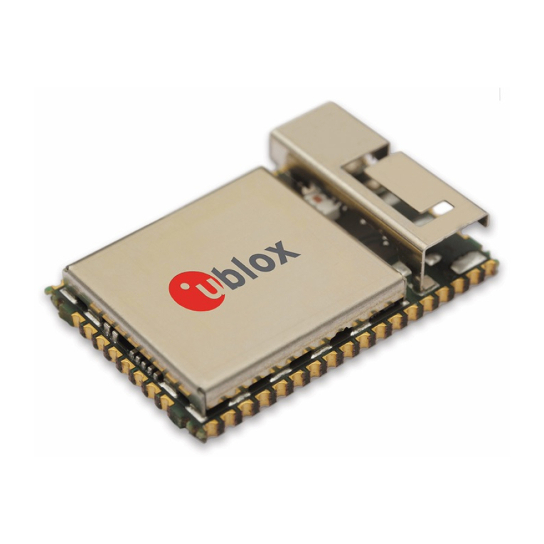
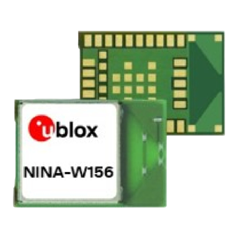
Ublox MAX-M5Q Quick setup guide

MAX-M5Q
GPS/GNSS modules
Hardware Integration Manual
Abstract
This document describes the features and specifications of the
MAX-M5Q in
MAX form factor with Mediatek hybrid/parallel
GPS/GGLONASS receiver. This stand-alone module is compact and
easy-to-integrate,
and provides an easy upgrade transition to the
future MAX-8 modules.
locate, communicate, accelerate
www.u-blox.com

Document Information - Hardware Integration Manual
FTX-HW-13008 Page 2 of 40
Document Information
Title MAX-M5Q
Subtitle GPS/GNSS modules
Document type Hardware Integration Manual
Document number FTX-HW-13008
Document status Objective Specification
Document status information
Objective
Specification
This document contains target values. Revised and supplementary data will be published
later.
Advance
Information
This document contains data based on early testing. Revised and supplementary data will be
published later.
Preliminary This document contains data from product verification. Revised and supplementary data may
be published later.
Released This document contains the final product specification.
This document applies to the following products:
Name Type number ROM/FLASH version PCN reference
MAX-M5Q-0 All Flash FW320G-UBX.3135
This document and the use of any information contained therein, is subject to the acceptance of the u-blox terms and conditions. They
can be downloaded from www.u-blox.com.
u-blox makes no warranties based on the accuracy or completeness of the contents of this document and reserves the right to make
changes to specifications and product descriptions at any time without notice.
u-blox reserves all rights to this document and the information contained herein. Reproduction, use or disclosure to third parties without
express permission is strictly prohibited. Copyright © 2013, u-blox AG.
u-blox®is a registered trademark of u-blox Holding AG in the EU and other countries. ARM®
is the registered trademark of ARM Limited in
the EU and other countries.

MAX-M5Q - Hardware Integration Manual
FTX-HW-13008 Objective Specification Preface
Page 3 of 40
Preface
u-blox Technical Documentation
As part of our commitment to customer support, u-blox maintains an extensive volume of technical
documentation for our products. In addition to our product-specific technical data sheets, the following manuals
are available to assist u-blox customers in product design and development.
•GPS Compendium, Doc No GPS-X-02007 [1]:This document, also known as the GPS book, provides a
wealth of information regarding generic questions about GPS system functionalities and technology.
•MAX-M5Q Receiver Description including Protocol Specification, Docu. No FTX-SW-13001 [2]:
Messages, configuration and functionalities of the MAX-M5Q software releases and positioning modules are
explained in this document.
•Hardware Integration Manuals: These manuals provide hardware design instructions and information on
how to set up production and final product tests.
•Application Notes: These documents provide general design instructions and information that applies to all
u-blox GPS/GNSS positioning modules.
•Related documents for a list of Application Notes related to your GPS/GNSS receiver.
How to use this Manual
The MAX-M5Q Hardware Integration Manual provides the necessary information to successfully design-in and
configure MT3333-based positioning modules. This manual has a modular structure. It is not necessary to read it
from the beginning to the end.
The following symbols highlight important information within the manual:
An index finger points out key information pertaining to module integration and performance.
A warning symbol indicates actions that could negatively influence or damage the module.
Questions
If you have any questions about MAX-M5Q Hardware Integration, please:
•Read this manual carefully.
•Contact our information service on the homepage http://www.u-blox.com
•Read the questions and answers on our FAQ database on the homepage http://www.u-blox.com

MAX-M5Q - Hardware Integration Manual
FTX-HW-13008 Objective Specification Preface
Page 4 of 40
Technical Support
Worldwide Web
Our website (www.u-blox.com) is a rich pool of information. Product information, technical documents and
helpful FAQ can be accessed 24h a day.
By E-mail
If you have technical problems or cannot find the required information in the provided documents, contact the
nearest of the Technical Support offices by email. Use our service pool email addresses rather than any personal
email address of our staff. This ensures that we process your request as soon as possible. You will find the
contact details at the end of the document.
Helpful Information when Contacting Technical Support
When contacting Technical Support please have the following information ready:
•Receiver type (e.g. NEO-7N-0-000), Datacode (e.g. 172100.0100.000) and firmware version (e.g. ROM1.0)
•Receiver configuration
•Clear description of your question or the problem together with a u-center logfile
•A short description of the application
•Your complete contact details

MAX-M5Q - Hardware Integration Manual
FTX-HW-13008 Objective Specification Contents
Page 5 of 40
Contents
Preface ................................................................................................................................3
Contents..............................................................................................................................5
1Quick reference ............................................................................................................8
2Hardware description ..................................................................................................8
2.1 Overview .............................................................................................................................................. 8
2.1.1 MAX-M5Q .................................................................................................................................... 8
2.2 Architecture.......................................................................................................................................... 8
2.2.1 MAX-M5Q Architecture ................................................................................................................ 8
2.3 Power management operating modes .................................................................................................. 9
2.3.1 Continuous mode ......................................................................................................................... 9
2.3.2 Power Save modes ........................................................................................................................ 9
2.3.3 Backup State ............................................................................................................................... 10
2.4 Configuration ..................................................................................................................................... 11
2.4.1 Configuration MAX-M5Q............................................................................................................ 11
2.5 Connecting power.............................................................................................................................. 11
2.5.1 VCC: Main Supply Voltage .......................................................................................................... 11
2.5.2 V_BCKP: Backup Supply Voltage ................................................................................................. 11
2.5.3 VCC_IO ....................................................................................................................................... 11
2.5.4 VCC_RF: Output Voltage RF section ............................................................................................ 11
2.6 Interfaces............................................................................................................................................ 12
2.6.1 UART........................................................................................................................................... 12
2.7 I/O pins............................................................................................................................................... 12
2.7.1 Antenna input ............................................................................................................................. 12
2.7.2 RESET_N: Reset input .................................................................................................................. 12
2.7.3 ANT_ON: Active Antenna control (LNA enable) ........................................................................... 12
2.7.4 TIMEPULSE .................................................................................................................................. 12
3Design .........................................................................................................................13
3.1 Design checklist .................................................................................................................................. 13
3.1.1 Schematic checklist ..................................................................................................................... 13
3.1.2 Layout checklist........................................................................................................................... 14
3.1.3 Antenna checklist ........................................................................................................................ 14
3.2 Design considerations for minimal designs.......................................................................................... 14
3.2.1 Minimal design............................................................................................................................ 15
3.3 Layout ................................................................................................................................................ 16
3.3.1 Footprint and paste mask ............................................................................................................ 16
4.1.1 Placement ................................................................................................................................... 16
4.1.2 Antenna connection and ground plane design ............................................................................ 17
4.1.3 General design recommendations: .............................................................................................. 18

MAX-M5Q - Hardware Integration Manual
FTX-HW-13008 Objective Specification Contents
Page 6 of 40
4.1.4 Antenna micro strip..................................................................................................................... 19
4.2 Antenna and Antenna supervision ...................................................................................................... 20
4.2.1 Antenna design with passive antenna ......................................................................................... 20
4.2.2 Active antenna design not using antenna supervisor ................................................................... 21
4.2.3 Design with GLONASS / GPS active antenna................................................................................ 23
4.2.4 Design with GLONASS / GPS passive antenna.............................................................................. 24
4.3 Recommended parts........................................................................................................................... 25
4.3.1 Recommended GPS & GLONASS active patch antenna (A1) ........................................................ 26
4.3.2 Recommended GPS & GLONASS passive patch antenna .............................................................. 26
4.3.3 Recommended GPS & GLONASS passive chip antenna ................................................................ 26
5Migration ....................................................................................................................27
5.1 Migrating from u-blox 7 designs to a MAX-M5Q module ................................................................... 27
5.1.1 Software compatibility................................................................................................................. 27
5.2 Forward compatibility from MAX-M5Q designs to a MAX-8x module ................................................. 27
5.2.1 Software compatibility................................................................................................................. 27
6Product handling ........................................................................................................28
6.1 Packaging, shipping, storage and moisture preconditioning ............................................................... 28
6.1.1 Population of Modules ................................................................................................................ 28
6.2 Soldering ............................................................................................................................................ 28
6.2.1 Soldering paste............................................................................................................................ 28
6.2.2 Reflow soldering ......................................................................................................................... 28
6.2.3 Optical inspection........................................................................................................................ 29
6.2.4 Cleaning...................................................................................................................................... 29
6.2.5 Repeated reflow soldering........................................................................................................... 30
6.2.6 Wave soldering............................................................................................................................ 30
6.2.7 Hand soldering............................................................................................................................ 30
6.2.8 Rework........................................................................................................................................ 30
6.2.9 Conformal coating ...................................................................................................................... 30
6.2.10 Casting........................................................................................................................................ 30
6.2.11 Grounding metal covers .............................................................................................................. 31
6.2.12 Use of ultrasonic processes.......................................................................................................... 31
6.3 EOS/ESD/EMI precautions ................................................................................................................... 31
6.3.1 Electrostatic discharge (ESD) ........................................................................................................ 31
6.3.2 ESD handling precautions............................................................................................................ 31
6.3.3 ESD protection measures............................................................................................................. 32
6.3.4 Electrical Overstress (EOS)............................................................................................................ 33
6.3.5 EOS protection measures............................................................................................................. 33
6.3.6 Electromagnetic interference (EMI) .............................................................................................. 33
6.3.7 Applications with wireless modules LEON / LISA .......................................................................... 34
7Product testing ...........................................................................................................36
7.1 u-blox in-series production test........................................................................................................... 36
7.2 Test parameters for OEM manufacturer.............................................................................................. 36
MAX-M5Q - Hardware Integration Manual
FTX-HW-13008 Objective Specification Contents
Page 7 of 40
7.3 System sensitivity test ......................................................................................................................... 37
7.3.1 Guidelines for sensitivity tests ...................................................................................................... 37
7.3.2 ‘Go/No go’ tests for integrated devices........................................................................................ 37
Appendix ..........................................................................................................................38
AAbbreviations .............................................................................................................38
Related documents...........................................................................................................39
Revision history................................................................................................................39
Contact..............................................................................................................................40

MAX-M5Q - Hardware Integration Manual
FTX-HW-13008 Objective Specification Quick reference
Page 8 of 40
1Quick reference
When using this manual for a design, make sure you also have the Data Sheet for the specific positioning
module (see the related documents section).
2Hardware description
2.1 Overview
2.1.1 MAX-M5Q
The u-blox MAX-M5Q is an OEM GNSS receiver module based on the Mediatek MT3333 chip that supports All-
in-One GNSS hybrid navigation. The u-blox MAX-M5Q receiver provides extremely low power and very fast TTFF
together with weak signal acquisition and tracking capability to meet even the most stringent performance
expectations in hybrid navigation, using signals from both GPS + GLONASS GNSS systems.
For product features see MAX-M5Q Data Sheet, Docu. No FTX-HW-13003 [1].
2.2 Architecture
2.2.1 MAX-M5Q Architecture
The MAX-M5Q is the newest standalone GPS/GNSS module from u-blox. With the exceptional utilization of GPS
and GLONASS in parallel, MAX-M5Q can enhance the position availability in harsh GNSS satellite visibility
conditions or at high latitudes, e.g. in the polar regions of Russia. It is characterized by a small footprint, low
power consumption, and sophisticated interference suppression, ensuring maximum performance even in GPS-
hostile environments. This makes incorporating MAX-M5Q into customer designs simple and straightforward.
Receiver type: MT3333 engine 99/33-channel (search/track)
Figure 1: MAX-M5Q Block diagram

MAX-M5Q - Hardware Integration Manual
FTX-HW-13008 Objective Specification Hardware description
Page 9 of 40
2.3 Power management operating modes
u-blox MAX-M5Q technology offers a power-optimized architecture with built-in autonomous power saving
functions to minimize power consumption at any given time. The receiver operates in two modes: Continuous
mode for best performance or Power Save mode for optimized power consumption. In addition, an integrated
high efficiency DC/DC converter allows low power consumption even for higher main supply voltages.
MAX-M5Q modules have the following operating modes:
•Continuous mode for best GPS/GNSS performance
•Power Save modes to optimize power consumption
oStandby mode
oPeriodic mode
oAlwaysLocateTM mode
•Backup state
2.3.1 Continuous mode
Continuous mode uses the acquisition engine at full performance resulting in the shortest possible TTFF and the
highest sensitivity. It searches for all possible satellites until the almanac is completely downloaded. The receiver
switches to the tracking engine to lower the power consumption when:
•A valid GPS/GNSS position is obtained
•The entire almanac has been downloaded
•The ephemeris for each satellite in view is valid
2.3.2 Power Save modes
For power sensitive applications, the MAX-M5Q module also supports low-power operating modes for reduced
power consumption by using the embedded power switch. For more information about the power management
command, see [2]. Use caution when implementing Backup, Periodic or to AlwaysLocate™ mode since forward
compatibility is not guaranteed.
2.3.2.1 Standby mode
In this mode, the receiver stops navigation, the internal processor enters standby state, and the current drain at
main supply VCC is typically reduced to 0.4 mA. Enter standby mode by sending the NMEA command:
$PMTK161,0*28. The host can wake up the module from Standby mode to Full Power mode by sending any
byte via the host port.
2.3.2.2 Periodic mode
This mode allows autonomous power on/off with reduced fix rate to reduce average power consumption, as
shown in Figure 2 below. The main power supply VCC is still active, but turning the supply on and off is
controlled internally by NMEA commands. Enter periodic mode by sending the following NMEA command:
$PMTK225,<Type>,<Run_time>,<Sleep_time>,<2nd_run_time>,<2nd_sleep_time>*<checksum>
where:
•Type=1 for Periodic Backup mode
•Run_time = Full Power period (ms)
•Sleep_time = Standby/Backup period (ms)
•2nd_run_time = Full Power period (ms) for extended acquisition if GNSS acquisition fails during Run_time
•2nd_sleep_time = Standby/Backup period (ms) for extended sleep if GNSS acquisition fails during Run_time
Example: $PMTK225,1,3000,12000,18000,72000*16 for periodic mode with 3 s navigation and 12 s sleep in
backup state. The acknowledgement response for the command is $PMTK001,225,3*35. The module can exit
Periodic mode by sending the command $PMTK225,0*2B just after the module wakes up from a previous sleep
cycle.

MAX-M5Q - Hardware Integration Manual
FTX-HW-13008 Objective Specification Hardware description
Page 10 of 40
Figure 2: Periodic Mode
2.3.2.3 AlwaysLocate mode
AlwaysLocate™ is an intelligent controller of the Periodic mode; the main power supply VCC is still active, but
supply is controlled internally by NMEA commands. Depending on the environment and motion conditions, the
module can autonomously and adaptively adjust the parameters of the Periodic mode, e.g. on/off ratio and fix
rate to achieve a balance in positioning accuracy and power consumption, see figure below. The average power
drain can vary based on conditions; typical average power is 7 mW. Associated profiles are: High and Low
Speed, Walking, Outdoor Static and Indoor.
Enter AlwaysLocate™ mode by sending the following NMEA command:
$PMTK225,<mode>*<checksum><CR><LF>
where mode=9 for AlwaysLocate™ in Backup mode. Example: $PMTK225,9*22. The acknowledgement
response for the command is $PMTK001,225,3*35. The module can exit AlwaysLocate™ mode by sending the
command $PMTK225,0*2B just after the module wakes up from a previous sleep cycle.
The module can control the embedded VCC power switch autonomously only after the MAX-M5Q is set to
Periodic or to AlwaysLocate™ mode by an NMEA command.
Note that first fix position accuracy can be somewhat degraded in Power Management modes when compared
to Full Power operation. The user can improve the position accuracy by taking the second or third fix after
waking up.
The user can exit low power modes to Full Power by sending NMEA command $PMTK225,0*2B just after the
module wakes up from a previous sleep cycle. For more information about power management command, see
[2].
2.3.3 Backup State
Backup State means a low quiescent (typically 10 μA at V_BCKP) power state where receiver operation is
stopped; only the backup supply V_BCKP is powered on while the main supply VCC is switched off by the host
(or autonomously by MAX-M5Q in Periodic mode and AlwaysLocateTM mode). Waking up from Backup State to
Full Power is controlled by the host by switching on the VCC supply.
After waking up, the receiver uses all internal aiding, including GNSS time, Ephemeris, and Last Position,
resulting in the fastest possible TTFF in either hot or warm start modes.
During Backup State, the I/O block is powered off. The suggestion is that the host forces its outputs to a low
state or to a high-Z state during the Backup State to minimize small leakage currents (<10 μA typically) at
receiver’s input signals.

MAX-M5Q - Hardware Integration Manual
FTX-HW-13008 Objective Specification Hardware description
Page 11 of 40
2.4 Configuration
2.4.1 Configuration MAX-M5Q
2.4.1.1 UART MAX-M5Q
UART Port 0 is normally used for GNSS data reports and receiver control. To configure serial data rates from
4,800 baud to 921,600 baud, use the command:
$PMTK251,<baud>*<checksum><CR><LF>
Ensure that the message payload fits in selected baud rate. Default baud rate is 115,200 baud; protocol is
NMEA. RX signal is pulled up internally and can be left floating (not connected) when not used.
Use caution when implementing MAX-M5Q configuration since forward compatibility is not
guaranteed.
2.5 Connecting power
The MAX-M5Q has three power supply pins: VCC, V_BCKP and VCC_IO.
2.5.1 VCC: Main Supply Voltage
The VCC pin provides the main supply voltage. During operation, the current drawn by the module can vary by
some orders of magnitude, especially if enabling low-power operation modes. For this reason, it is important
that the supply circuitry be able to support the peak power for a short time (see datasheet for specification).
When switching from backup mode to normal operation or at startup, MAX-M5Q modules must charge
the internal capacitors in the core domain. In certain situations, this can result in a significant current
draw. For low power applications using Power Save and backup modes it is important that the power
supply or low ESR capacitors at the module input can deliver this current/charge.
Use a proper GND concept. Do not use any resistors or coils in the power line. For ground plane design
see section 4.1.2
2.5.2 V_BCKP: Backup Supply Voltage
In case of a power failure on the module supply, V_BCKP supplies power to the real-time clock (RTC) and
battery backed RAM (BBR). Use of valid time and the GPS/GNSS orbit data at startup will improve the GPS/GNSS
performance, i.e. enables hot and warm starts. If no backup battery is connected, the module performs a cold
start at power up.
If no backup supply voltage is available, connect the V_BCKP pin to VCC.
V_BCKP provides supply all the time to backup memory & RTC. Since there is no internal switch to
provide backup supply via VCC_IO, the V_BCKP current will increase while navigating. That will drain
the backup battery faster.
2.5.3 VCC_IO
For compatibility (migration path for MAX-7 and MAX-8), Pin 7 (Reserved) must be connected to VDD.
2.5.4 VCC_RF: Output Voltage RF section
The VCC_RF pin can supply an active antenna or external LNA. For more information, see section 4.2.2.

MAX-M5Q - Hardware Integration Manual
FTX-HW-13008 Objective Specification Hardware description
Page 12 of 40
2.6 Interfaces
2.6.1 UART
The MAX-M5Q positioning module includes a Universal Asynchronous Receiver Transmitter (UART) serial
interface RxD/TxD that supports configurable baud rates. For information about the supported baud rates, see
the MAX-M5Q Receiver Description including Protocol Specification, Docu. No FTX-SW-13001 [2].
The signal output and input levels are 0 V to VCC. An interface based on RS232 standard levels (+/- 12 V) can be
implemented using level shifters such as Maxim MAX3232. Hardware handshake signals and synchronous
operation are not supported.
2.7 I/O pins
2.7.1 Antenna input
The antenna provides simultaneous reception of all frequencies from 1560 to 1606 MHz. The module supports
both passive and active antennas. For higher sensitivity, use active antennas or an external LNA with passive
antennas. The antenna input RF_IN impedance is 50 Ω. The RF input signal path contains a SAW band-pass filter
before the internal LNA, which provides good out-of-band protection against GNSS blocking caused by possible
nearby wireless transmitters.
For recommended parts, see section 4.3.
2.7.2 RESET_N: Reset input
Driving RESET_N low activates a hardware reset of the system. Use this pin only to reset the module. Do not use
RESET_N to turn the module on and off, since the reset state increases power consumption.
2.7.3 ANT_ON: Active Antenna control (LNA enable)
In Power Save Mode, the system can turn on/off an optional external LNA using the ANT_ON signal in order to
optimize power consumption. Polarity is active high.
2.7.4 TIMEPULSE
The TIMEPULSE (PPS) output signal provides a pulse-per-second output signal for timing purposes. The MAX-
M5Q time pulse signal is one pulse per second.
The PPS output is valid when navigation is valid and will also continue to ‘freewheel’ after a valid fix is lost by a
certain navigation DR timeout of typically 10 seconds.
Pulse length (high) is 100ms and UTC sync is at rising edge.

MAX-M5Q - Hardware Integration Manual
FTX-HW-13008 Objective Specification Design
Page 13 of 40
3Design
3.1 Design checklist
Designing-in a MAX-M5Q module is easy, especially when based on a u-blox reference design. Nonetheless, it
pays to do a quick sanity check of the design. This section lists the most important items for a simple design
check. The design checklist can also help to avoid an unnecessary PCB respin and achieve the best possible
performance. Follow the design checklists when developing any MAX-M5Q GPS/GNSS applications. This can
significantly reduce development time and costs.
3.1.1 Schematic checklist
Power supply requirements
GPS/GNSS positioning modules require a stable power supply. In selecting a strategy to achieve a clean
and stable power supply, any resistance in the VCC supply line can negatively influence performance.
Consider the following points:
oWide power lines or even power planes are preferred.
oAvoid resistive components in the power line (e.g. narrow power lines, coils, resistors, etc.).
oPlacing a filter or other source of resistance at VCC can create significantly longer acquisition
times.
oFor ground plane design, see section 3.4.3.
Ensure that all power supplies are within the specified range. (See MAX-M5Q Data Sheet, Docu. No FTX-
HW-13003 [1])
Compare the peak supply current consumption of your MAX-M5Q module with the specification of the
power supply. (See MAX-M5Q Data Sheet, Docu. No FTX-HW-13003 [1])
At the module input, use low ESR capacitors that can deliver the required current/charge for switching
from backup mode to normal operation.
For compatibility (migration path for MAX-7 and MAX-8), Pin 7 (Reserved) must be connected to VDD.
Backup battery
Use of valid time and the GPS/GNSS orbit data at startup will improve the GPS/GNSS performance, i.e.
enables hot and warm starts. To make use of these features connect a battery to V_BCKP to continue
supplying the backup domain in case of power failure at VCC.
If no backup supply voltage is available, connect the V_BCKP pin to VCC).

MAX-M5Q - Hardware Integration Manual
FTX-HW-13008 Objective Specification Design
Page 14 of 40
3.1.2 Layout checklist
See section 3.3 for more details on the layout.
Position the GPS/GNSS module according to the recommendation.
Follow the grounding concept.
Keep the micro strip as short as possible.
Add a ground plane underneath the GPS/GNSS module to reduce interference.
For improved shielding, add as many vias as possible around the micro strip, around the serial
communication lines, underneath the GPS/GNSS module, etc.
Include appropriate EOS/ESD/EMI protection measures. This is especially important for designs including
wireless modules.
3.1.3 Antenna checklist
The total noise figure should be well below 3 dB.
If a patch antenna is the preferred antenna, choose a patch of at least 15x15x4 mm for standalone
GPS/QZSS, or choose a patch of at least 25x25x4 mm for GPS + GLONASS. For smaller antennas, an LNA
with a noise figure <2 dB is recommended.
Make sure the antenna is not located close to noisy parts of the circuitry (e.g. micro-controller or display).
To optimize performance in environments with out-of-band jamming sources, use an additional SAW
filter.
The micro strip must be 50 Ωand be routed in a section of the PCB where minimal interference from
noise sources can be expected.
In case of a multi-layer PCB, use the thickness of the dielectric between the signal and the first GND layer
(typically the 2nd layer) for the micro strip calculation.
If the distance between the micro strip and the adjacent GND area (on the same layer) does not exceed 5
times the track width of the micro strip, use the “Coplanar Waveguide” model in AppCad to calculate
the micro strip and not the “micro strip” model. See section 4.1.4.
Use an external LNA if your design does not include an active antenna when optimal performance is
important.
For information on ESD protection for patch antennas and removable antennas, see section 6.3.3 and if
you use GPS for design in combination with GSM or other radio, then check sections 6.3.5 to 6.3.7.
For more information dealing with interference issues, see the GPS Antenna Application Note [3].
3.2 Design considerations for minimal designs
For a minimal design with the MAX-M5Q GPS/GNSS module, the following functions and pins need
consideration:
•Connect the Power supply to VCC.
•Assure an optimal ground connection to all ground pins of the module.
•Connect the antenna to RF_IN over a 50 Ω
•If you need improved startup or use AssistNow Autonomous in your application, connect a backup supply
voltage to V_BCKP.

MAX-M5Q - Hardware Integration Manual
FTX-HW-13008 Objective Specification Design
Page 15 of 40
3.2.1 Minimal design
This is a minimal setup for a GPS/GNSS receiver:
Figure 3: MAX-M5Q passive antenna design
For information on increasing immunity to jammers such as GSM, see section 6.3.7.
Function PIN No I/O Description Remarks
Power VCC 8 I Supply Voltage Provide clean and stable supply.
GND 1,10,12 I Ground Assure a good GND connection to all GND pins of the module,
preferably with a large ground plane.
V_BCKP 6 I Backup Supply
Voltage
Backup supply voltage input pin. Connect to VCC if not used.
Antenna RF_IN 11 I GPS signal
input from
antenna
The connection to the antenna has to be routed on the PCB. Use a
controlled impedance of 50 Ωto connect RF_IN to the antenna or
the antenna connector. DC block inside.
VCC_RF 14 O Output Voltage
RF section
Can be used for active antenna or external LNA supply.
ANT_ON 13 O ANT_ON Active antenna or ext. LNA control pin in power save mode.
ANT_ON pin voltage level is VCC
UART TXD 2 O Serial Port UART, leave open if not used, Voltage level referred VCC.
RXD 3 I Serial Port
UART, leave open if not used, Voltage level referred VCC
System TIMEPULSE 4 O Timepulse
Signal
Leave open if not used, Voltage level referred VCC
VRESET 9 I RESET_N Reset
Reserved 7 - Reserved Connected to VDD (VCC_IO)
Reserved 5, 15, 16,
17, 18
- Reserved Leave open
Table 1: Pinout MAX-M5Q

MAX-M5Q - Hardware Integration Manual
FTX-HW-13008 Objective Specification Design
Page 16 of 40
3.3 Layout
This section provides important information for designing a robust GPS/GNSS system.
GPS/GNSS signals at the surface of the Earth are about 15 dB below the thermal noise floor. Signal loss from the
antenna to RF_IN pin of the module must be minimized as much as possible. When defining a GPS/GNSS
receiver layout, the placement of the antenna with respect to the receiver, as well as grounding, shielding and
jamming from other digital devices, are crucial issues requiring careful consideration.
3.3.1 Footprint and paste mask
Figure 4 describes the footprint and provides recommendations for the paste mask for MAX-M5Q LCC modules.
These are recommendations only and not specifications. Note that the Copper and Solder masks have the same
size and position.
To improve the wetting of the half vias, reduce the amount of solder paste under the module and increase the
volume outside of the module by defining the dimensions of the paste mask to form a T-shape (or equivalent)
extending beyond the Copper mask. For the stencil thickness, see section 6.2.1.
9.7 mm [382 mil]
10.1 mm [398 mil]
1.0 mm
[39.3 mil]
0.7 mm
[27.6 mil]
0.8 mm
[31.5 mil]
0.65 mm
[26.6 mil]
1.1 mm
[43.3 mil]
0.8 mm
[31.5 mil]
Figure 4: MAX-M5Q footprint
Stencil: 150
µ
m
7.9 mm [311 mil]
12.5 mm [492 mil]
9.7 mm [382 mil]
0.7 mm
[27.6 mil]
0.5 mm
[19.7 mil]
0.8 mm
[31.5 mil]
0.6 mm
[23.5 mil]
4Figure 5: MAX-M5Q paste mask
Consider the paste mask outline when defining the minimal distance to the next component. The exact
geometry, distances, stencil thicknesses and solder paste volumes must be adapted to the specific
production processes (e.g. soldering) of the customer.
4.1.1 Placement
A very important factor in achieving maximum performance is the placement of the receiver on the PCB. The
connection to the antenna must be as short as possible to avoid jamming into the very sensitive RF section.
Make sure that the RF critical circuits are separate from any other digital circuits on the system board. To achieve
this, position the module’s digital part towards the digital section on the system PCB. Exercise care if placing the
receiver in proximity to heat emitting circuitry. The RF part of the receiver is very sensitive to temperature, and
sudden changes can have an adverse impact on performance.
The RF part of the receiver is a temperature sensitive component. Avoid high temperature
drift and air vents near the receiver.

MAX-M5Q - Hardware Integration Manual
FTX-HW-13008 Objective Specification Design
Page 17 of 40
Non 'emitting'
circuits
PCB
Digital & Analog circuits
Non
'emitting'
circuits
Antenna
Digital Part
RF Part
1
2
3
4
5
6
7
8
9
10
11
12
13
14
28
27
26
25
24
23
22
21
20
19
18
17
16
15
RF & heat
'emitting'
circuits
PCB
Digital & Analog circuits
RF& heat
'emitting'
circuits
Antenna
1
2
3
4
5
6
7
8
9
10
11
12
13
14
28
27
26
25
24
23
22
21
20
19
18
17
16
15
Figure 6: Placement (for exact pin orientation, see data sheet)
4.1.2 Antenna connection and ground plane design
u-blox 7 modules can be connected to passive or active antennas. The RF connection is on the PCB and connects
the RF_IN pin with the antenna feed point or the signal pin of the connector. Figure 7 illustrates connection to a
typical five-pin RF connector. One can see the improved shielding for digital lines as discussed in the GPS
Antenna Application Note [3]. Depending on the actual size of the ground area, if possible place additional vias
in the outer region. In particular, terminate the edges of the ground area with a dense line of vias.
Figure 7: Recommended layout (for exact pin orientation, see data sheet)

MAX-M5Q - Hardware Integration Manual
FTX-HW-13008 Objective Specification Design
Page 18 of 40
As seen in Figure 7,an isolated ground area exists around and below the RF connection. This part of the circuit
MUST be kept as far from potential noise sources as possible. Make certain that no signal lines cross, and that no
signal trace vias appear at the PCB surface within the area of the red rectangle. The ground plane should also be
free of digital supply return currents in this area. On a multi layer board, the whole layer stack below the RF
connection should be kept free of digital lines. This is because even solid ground planes provide only limited
isolation.
The impedance of the antenna connection must match the 50 Ωimpedance of the receiver. To achieve an
impedance of 50 Ω, the width W of the micro strip has to be chosen depending on the dielectric thickness H,
the dielectric constant εrof the dielectric material of the PCB and on the build-up of the PCB (see section 4.1.4).
Figure 8 shows two different builds: A 2 Layer PCB and a four Layer PCB. The reference ground plane is in both
designs on layer 2 (red). Therefore, the effective thickness of the dielectric is different.
Module micro strip line
Ground plane
Module micro strip line
Ground plane
PCB
PCB
Either don't use these layers or fill with ground planes
HH
Figure 8: PCB build-up for micro strip line. Left: 2-layer PCB, right: 4-layer PCB
4.1.3 General design recommendations:
•Keep the length of the micro strip line as short as possible. Avoid lengths over 2.5 cm (1 inch) on standard
PCB material and without additional shielding.
•For multi-layer boards, the distance between micro strip line and ground area on the top layer should at
least be as large as the dielectric thickness.
•Avoid routing the RF connection close to digital sections of the design.
•To reduce signal reflections, avoid sharp angles in the routing of the micro strip line. Chamfers or fillets are
preferred for rectangular routing; 45-degree routing is preferred over Manhattan style 90-degree routing.
Antenna
Antenna
Antenna
PCB
PCB PCB
1
2
3
4
5
6
7
8
9
10
11
12
13
14
28
27
26
25
24
23
22
21
20
19
18
17
16
15
1
2
3
4
5
6
7
8
9
10
11
12
13
14
28
27
26
25
24
23
22
21
20
19
18
17
16
15
1
2
3
4
5
6
7
8
9
10
11
12
13
14
28
27
26
25
24
23
22
21
20
19
18
17
16
15
Wrong better best
Figure 9: Recommended micro strip routing to RF pin (for exact pin orientation see data sheet)
•Do not route the RF-connection underneath the receiver. The distance of the micro strip line to the ground
plane on the bottom side of the receiver is very small (some 100 µm) and has huge tolerances (up to 100%).
Therefore, the impedance of this part of the trace cannot be controlled.
•Use as many vias as possible to connect the ground planes.
•In order to avoid reliability hazards, cover the area on the PCB under the receiver entirely with solder mask.
Vias should not be open. Do not route under the receiver.

MAX-M5Q - Hardware Integration Manual
FTX-HW-13008 Objective Specification Design
Page 19 of 40
4.1.4 Antenna micro strip
There are many ways to design wave-guides on printed circuit boards. A common factor to all is that calculation
of the electrical parameters is not straightforward. Freeware tools like AppCAD from Agilent or TXLine from
Applied Wave Research, Inc. are of great help in this regard. Download these tools from www.agilent.com or
www.hp.woodshot.com and www.mwoffice.com.
Micro strip is the most commonly used configuration on printed circuit boards; see Figure 10 and Figure 11. As a
rule of thumb, to achieve a 50 Ωline impedance with FR-4 material, the width of the conductor is roughly
double the thickness of the dielectric.
For the correct calculation of the micro strip impedance, one does not only need to consider the
distance between the top and the first inner layer, but also the distance between the micro strip and the
adjacent GND plane on the same layer.
Use the Grounded Coplanar Waveguide model for the calculation of the line dimensions.
Figure 10: Micro strip on a 2-layer board (Agilent AppCAD Coplanar Waveguide)
Figure 10 shows an example of a 2-layer FR4 board with 1.6 mm thickness (H) and a 35 µm (1 ounce) copper
cladding (T). The thickness of the micro strip is comprised of the cladding (35 µm) plus the plated copper
(typically 25 µm). Figure 11 is an example of a multi layer FR4 board with 18 µm (½ ounce) cladding (T) and 180
µm dielectric between layer 1 and 2.
Figure 11: Micro strip on a multi layer board (Agilent AppCAD Coplanar Waveguide)

MAX-M5Q - Hardware Integration Manual
FTX-HW-13008 Objective Specification Design
Page 20 of 40
4.2 Antenna and Antenna supervision
4.2.1 Antenna design with passive antenna
A design using a passive antenna requires more attention to the layout of the RF section. Typically, a passive
antenna is located near electronic components; therefore, care should be taken to reduce electrical ‘noise’ that
may interfere with the antenna performance. Passive antennas do not require a DC bias voltage and can be
directly connected to the RF input pin RF_IN. Sometimes, they may also need a passive matching network to
match the impedance to 50 Ω.
4.2.1.1 Minimal setup with a good patch antenna
Figure 3 shows a minimal setup for a design with a good GPS patch antenna.
4.2.1.2 Setup for best performance with passive antenna
Figure 12 shows a design using an external LNA to increase the sensitivity for best performance with passive
antenna.
Figure 12: Module design with passive antenna and an external LNA (for exact pin orientation, see data sheet)
ANT_ON (antenna on) can be used to turn on and off an optional external LNA.
The VCC_RF output can be used to supply the LNA with a filtered supply voltage.
For recommended parts, see section 4.3
A standard GPS LNA has enough bandwidth to amplify GPS and GLONASS signals.
Table of contents
Other Ublox Wireless Module manuals

Ublox
Ublox NINA-B3 Series Quick setup guide

Ublox
Ublox TOBY-R2 Series Quick setup guide

Ublox
Ublox NINA-W1 Series Quick setup guide

Ublox
Ublox LISA-C200 Installation and operating instructions

Ublox
Ublox C94-M8P User manual

Ublox
Ublox C101-D9S User manual

Ublox
Ublox NORA-W30 Series Quick setup guide

Ublox
Ublox LEON-G100 ECALL Quick setup guide

Ublox
Ublox ODIN-W2 Series Quick setup guide

Ublox
Ublox EVK-R4 Series User manual