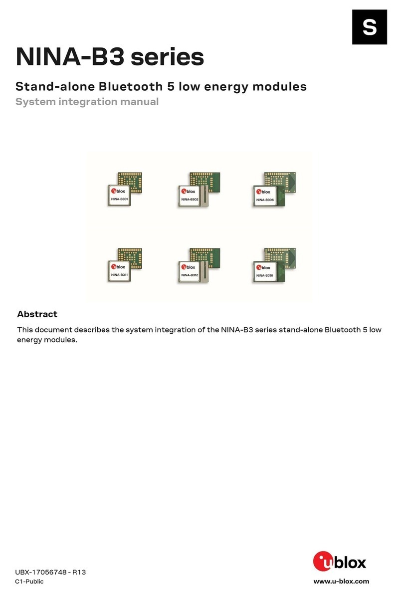
Ublox NINA-B4 Series Quick setup guide

UBX-19052230 - R06
C1-Public www.u-blox.com
NINA-B4 series
Stand-alone Bluetooth 5.1 low energy modules
System integration manual
Abstract
Used together with the respective module data sheets that describe the pinout and module
functions, this manual provides a functional overview combined with best-practice design guidelines
for integrating the short-
range module in an end product. With several supporting examples, the
document explains how applications are developed for NINA-B4 open cpu solutions using the Nordic
SDK. It also describes the options for flashing the u-
connectXpress module software in production
environments.

NINA-B4 series - System integration manual
UBX-19052230 - R06 Document information Page 2 of 45
C1-Public
Document information
Title NINA-B4 series
Subtitle Stand-alone Bluetooth 5.1 low energy modules
Document type System integration manual
Document number UBX-19052230
Revision and date R06 22-Jan-2021
Disclosure restriction C1-Public
Document status Description
Functional sample Draft For functional testing. Revised and supplementary data will be published later.
In development /
Prototype
Objective specification Target values. Revised and supplementary data will be published later.
Engineering sample Advance information Data based on early testing. Revised and supplementary data will be published later.
Initial production Early production information Data from product verification. Revised and supplementary data may be published later.
Mass production /
End of life
Production information Document contains the final product specification.
This document applies to the following products:
Product name Document status
NINA-B400 Early Production Information
NINA-B401 Prototype
NINA-B406 Early Production Information
NINA-B410 Early Production Information
NINA-B411 Prototype
NINA-B416 Early Production Information
☞For information about the related hardware, software, and status of listed product types, refer to
the respective data sheets [2][3].
u-blox or third parties may hold intellectual property rights in the products, names, logos and designs included in this
document. Copying, reproduction, modification or disclosure to third
parties of this document or any part thereof is only
permitted with the express written permission of u
-blox.
The information contained herein is provided “as is” and u
-blox assumes no liability for its use. No warranty, either express or
implied, is given
, including but not limited to, with respect to the accuracy, correctness, reliability and fitness for a particular
purpose of the information. This document may be revised by u
-blox at any time without notice. For the most recent
documents, visit www.u
-blox.com.
Copyright © u
-blox AG.
u-blox or third parties may hold intellectual property rights in the products, names, logos and designs included in this
document. Copying, reproduction, modification or disclosure to third parties of this document or any part
thereof is only
permitted with the express written permission of u
-blox.
The information contained herein is provided “as is” and u
-blox assumes no liability for its use. No warranty, either express or
implied, is given, including but not limited
to, with respect to the accuracy, correctness, reliability and fitness for a particular
purpose of the information. This document may be revised by u
-blox at any time without notice. For the most recent
documents, visit www.u
-blox.com.
Copyright © u
-blox AG.

NINA-B4 series - System integration manual
UBX-19052230 - R06 Contents Page 3 of 45
C1-Public
Contents
Document information .............................................................................................................................2
Contents .......................................................................................................................................................3
1Functional description.......................................................................................................................5
1.1 Overview........................................................................................................................................................5
1.2 Applications .................................................................................................................................................6
1.3 Block diagrams ............................................................................................................................................7
1.3.1 NINA-B40..............................................................................................................................................7
1.3.2 NINA-B41..............................................................................................................................................8
1.4 Product description ....................................................................................................................................9
1.4.1 NINA-B40 series..................................................................................................................................9
1.4.2 NINA-B41 series..................................................................................................................................9
1.5 Hardware options........................................................................................................................................9
1.6 Software options.......................................................................................................................................10
1.6.1 Open CPU............................................................................................................................................11
1.6.2 u-connectXpress software .............................................................................................................11
1.7 Bluetooth device address ........................................................................................................................12
1.8 Pin configurations and functions ..........................................................................................................12
1.8.1 NINA-B40 pins...................................................................................................................................12
1.8.2 NINA-B41 pins...................................................................................................................................13
1.9 Low power clock ........................................................................................................................................13
1.9.1 External crystal .................................................................................................................................14
1.9.2 Internal oscillator..............................................................................................................................14
1.9.3 External clock source .......................................................................................................................14
2Design-in............................................................................................................................................. 15
2.1 NINA family migration design.................................................................................................................15
2.2 Supply interfaces ......................................................................................................................................15
2.2.1 Main supply input .............................................................................................................................15
2.2.2 Digital I/O interfaces reference voltage (VCC_IO)......................................................................15
2.2.3 VCC application circuits ..................................................................................................................15
2.3 Antenna interface.....................................................................................................................................16
2.3.1 External antenna selection.............................................................................................................17
2.3.2 NINA-B4x6 design-in........................................................................................................................21
2.4 NFC interface.............................................................................................................................................22
2.4.1 Battery protection ............................................................................................................................23
2.5 Debug interface .........................................................................................................................................23
2.6 General layout guidelines ........................................................................................................................24
2.6.1 General considerations for schematic design and PCB floor-planning.................................24
2.6.2 Layout and manufacturing.............................................................................................................24
2.6.3 Thermal guidelines ...........................................................................................................................25
2.6.4 ESD guidelines...................................................................................................................................25

NINA-B4 series - System integration manual
UBX-19052230 - R06 Contents Page 4 of 45
C1-Public
2.7 Product testing..........................................................................................................................................26
2.7.1 u-blox in-series production tests...................................................................................................26
2.7.2 OEM manufacturer production test .............................................................................................27
3Open CPU software ......................................................................................................................... 28
3.1 Nordic SDK .................................................................................................................................................28
3.1.1 Getting started with the Nordic SDK............................................................................................28
3.1.2 Bluetooth device (MAC) address and other production data..................................................31
3.1.3 Definition of Low Frequency clock source ...................................................................................31
3.2 Flashing open CPU software ..................................................................................................................31
3.2.1 Flashing over the SWD interface...................................................................................................31
3.2.2 Flashing over the UART interface .................................................................................................32
4u-connectXpress software............................................................................................................ 34
4.1 Flashing NINA-B41 u-connectXpress software..................................................................................34
4.1.1 Software flashing using s-center..................................................................................................34
4.1.2 Software flashing using AT command.........................................................................................35
4.2 Low frequency clock source....................................................................................................................37
5Handling and soldering................................................................................................................... 38
5.1 Packaging, shipping, storage, and moisture preconditioning .........................................................38
5.2 Handling......................................................................................................................................................38
5.3 Soldering .....................................................................................................................................................38
5.3.1 Reflow soldering process ................................................................................................................38
5.3.2 Cleaning ..............................................................................................................................................39
5.3.3 Other remarks ...................................................................................................................................40
Appendix .................................................................................................................................................... 41
AGlossary .............................................................................................................................................. 41
Related documents ................................................................................................................................ 43
Revision history ....................................................................................................................................... 44
Contact....................................................................................................................................................... 45

NINA-B4 series - System integration manual
UBX-19052230 - R06 Functional description Page 5 of 45
C1-Public
1Functional description
1.1 Overview
The NINA-B4 series is comprised of small, standalone Bluetooth low energy wireless modules
featuring full Bluetooth 5.1.
Based on the Nordic Semiconductor nRF52833 chip that includes an integrated RF core and powerful
Arm® Cortex®-M4 processor with FPU, NINA-B4 modules include the S140 SoftDevice radio stack
that operates as a Bluetooth 5.1 low energy central and peripheral protocol stack solution – as well as
in Thread, Zigbee 802.15.4, and Nordic proprietary modes (NINA-B40 only).
For a flexible and innovative approach to application design, two conceptually different architecture
solutions are available: u-connectXpress (B41) or open cpu (B40). End-user products based on either
architecture are developed on pre-certified u-blox reference designs that are qualified with the
regional regulatory bodies for your chosen product markets. This approach to application
development provides good opportunity for less compliance testing, lower development cost, and
reduced time to market.
With an operational temperature range that spans from -40 up to +105°C, NINA-B4 modules are ideal
for harsh industrial or lighting applications that must operate at high ambient temperatures. NINA-
B41 also caters towards applications in smart buildings, smart cities, industrial automation systems,
sensor networks and asset tracking solutions.
Featuring Angle of Arrival (AoA) and Angle of Departure (AoD) transceivers, the NINA-B40 series
supports the Bluetooth 5.1 Direction Finding service. The service can be used for indoor positioning,
wayfinding, and asset tracking.
NINA-B4 modules integrates internal power management circuitry requiring only a single supply
voltage in the range of 1.7 – 3.6 V. The broad supply range also makes the modules particularly useful
in battery powered systems.
With the same pinout, physical size, and mechanical design of NINA-B3 modules, NINA-B4 offers a
natural upgrade path for existing NINA applications.
Table 1 describes the various models in the NINA-B40 series.
Model Description
NINA-B400 Bluetooth 5.1 module that includes a powerful Arm® Cortex®-M4 with FPU and delivers state-of-the-
art
power performance. All NINA-B40 variants are open CPU modules
that enable customer applications to
run on the built-in Arm® Cortex®-
M4 with FPU. With 512 kB flash and 128 kB RAM, these modules offer
respectable capacity for customer applications on top of the Bluetooth Low Energy stack.
NINA-B400 has a U.FL connector for use with an external antenna.
NINA-B401 Bluetooth 5.1 module that includes a powerful Arm® Cortex®-M4 with FPU and delivers state-of-the-
art
power performance. All NINA-B40 variants are open CPU modules
that enable customer applications to
run on the built-in Arm® Cortex®-M4 with FPU. With
512 kB flash and 128 kB RAM, these modules offer
respectable capacity for customer applications on top of the Bluetooth Low Energy stack.
NINA-B401 has an RF pin for use with an external antenna.
NINA-B406 Bluetooth 5.1 module that includes a powerful Arm® Cortex®-M4 with FPU and delivers state-of-the-
art
power performance. All NINA-
B40 variants are open CPU modules that enable customer applications to
run on the built-in Arm® Cortex®-
M4 with FPU. With 512 kB flash and 128 kB RAM, these modules offer
respectable capacity for customer applications on top of the Bluetooth Low Energy stack. NINA-
B406 has
an internal PCB trace antenna with an extensive range. The antenna is
specifically designed for embedded
devices.
Table 1: NINA-B40 series

NINA-B4 series - System integration manual
UBX-19052230 - R06 Functional description Page 6 of 45
C1-Public
Table 2 describes the different models in the NINA-B41 series.
Model Description
NINA-B410 Bluetooth 5.1 module that includes a powerful Arm® Cortex®-M4 with FPU and delivers state-of-the-
art
power performance. All NINA-B41 variants have u-connectXpress software pre-flashed.
NINA-B410 has a U.FL connector for use with an external antenna.
NINA-B411 Bluetooth 5.1 module that includes a powerful Arm® Cortex®-M4 with FPU and delivers state-of-the-
art
power performance. All NINA-B41 variants have u-connectXpress software pre-flashed.
NINA-B411 has an RF pin for use with an external antenna.
NINA-B416 Bluetooth 5.1 module that includes a powerful Arm® Cortex®-M4 with FPU and delivers state-of-the-
art
power performance. All NINA-B41 variants have u-connectXpress software pre-flashed.
NINA-B416 has an internal PCB trace antenna with an extensive range. The antenna is
specifically
designed for embedded devices.
Table 2: NINA-B41 series
☞Already globally certified for use with an internal antenna or range of external antennas, the time,
cost, and effort spent on deploying NINA-B4 modules into customer applications is reduced
significantly.
1.2 Applications
•Industrial automation
•Smart buildings and cities
•Low power sensors
•Wireless-connected and configurable equipment
•Point-of-sales
•Health devices
•Real-time Location, RTLS
•Indoor positioning
•Asset tracking

NINA-B4 series - System integration manual
UBX-19052230 - R06 Functional description Page 7 of 45
C1-Public
1.3 Block diagrams
Block diagrams of the NINA-B40 and NINA-B41 module designs are shown in Figure 1 and Figure 2.
1.3.1 NINA-B40
A block diagram of the NINA-B40 open-cpu module design showing the alternative U.FL connector
(B400), antenna pin (B401), and PCB trace antenna (B406) solutions is shown in Figure 1.
☞NINA-B400 modules include a U.FL connector for connecting an external antenna. The module size
is 10 x 15 x 2.2 mm.
☞NINA-B401 modules include an ANT pad on the footprint for connecting an external antenna. The
module size is 10 x 11.6 x 2.2 mm.
☞NINA-B406 module support an internal PCB trace antenna using antenna technology from Proant
AB. The module size is 10 x 15 x 2.2 mm.
Figure 1: NINA-B40 series block diagram
DC/DC and LDO regulators
512 kB flash
Bluetooth LE
baseband
IO buffers
Arm® Cortex®-M4
with FPU
PLL
VCC_IO (1.7
– 3.6 V)
VCC (1.7
– 3.6 V)
32 MHz
Reset
2x UART
SPI
GPIO
1.3 V
System
power
I2C
PWM
I2S
ADC and
comparator
Analog
Passive NFC tag
NFC
128 kB
RAM
PLL
32.768 kHz
RTC, timers
and counters
RF
Nordic Semiconductor
nRF52833
USB device
USB 2.0
QDEC
PDM
(NINA-B406)
PCB trace antenna
(NINA-B400)
U.FL antenna connector
(NINA-B401)
Antenna pin

NINA-B4 series - System integration manual
UBX-19052230 - R06 Functional description Page 8 of 45
C1-Public
1.3.2 NINA-B41
A block diagram of the NINA-B4 u-connect module design showing the alternative U.FL connector
(B410), antenna pin (B411), and PCB trace antenna (B416) solutions is shown in Figure 2.
☞NINA-B410 modules support a U.FL connector to accommodate an external antenna. The module
size is 10 x 15 x 2.2 mm.
☞NINA-B411 modules have a footprint arrangement that includes an ANT pad for connecting an
external antenna. The module size is 10 x 11.6 x 2.2 mm.
☞NINA-B416 modules support an internal PCB trace antenna using antenna technology from
Proant AB. The module size is 10 x 15 x 2.2 mm.
Figure 2: NINA-B41 series block diagram
DC/DC and LDO regulators
512 kB flash
Bluetooth LE
baseband
IO buffers
Arm® Cortex®-M4
with FPU
PLL
VCC_IO (1.7
– 3.6 V)
VCC (1.7
– 3.6 V)
32 MHz
Reset
2x UART
GPIO
1.3 V
System
power
ADC and
comparator
Passive NFC tag
NFC
128 kB
RAM
PLL
32.768 kHz
RTC, timers
and counters
RF
Nordic Semiconductor
nRF52833
USB device
(NINA-B416)
PCB trace antenna
(NINA-B410)
U.FL antenna connector
(NINA-B411)
Antenna pin

NINA-B4 series - System integration manual
UBX-19052230 - R06 Functional description Page 9 of 45
C1-Public
1.4 Product description
Please see the data sheet for the respective product family [2] [3] for the latest data.
1.4.1 NINA-B40 series
Item NINA-B400 NINA-B401 NINA-B406
Bluetooth version 5.1 5.1 5.1
Band support 2.4 GHz, 40 channels 2.4 GHz, 40 channels 2.4 GHz, 40 channels
Typical conducted output power +8 dBm +8 dBm -
Radiated output power (EIRP) +11 dBm (with typical
antenna)
+11 dBm (with typical
antenna)
+11 dBm
RX sensitivity (conducted) -95 dBm -95 dBm -95 dBm
RX sensitivity, long range mode
(conducted)
-102 dBm -102 dBm -102 dBm
Supported 2.4 GHz radio modes Bluetooth Low Energy
IEEE 802.15.4
Proprietary 2.4 GHz modes
Bluetooth Low Energy
IEEE 802.15.4
Proprietary 2.4 GHz modes
Bluetooth Low Energy
IEEE 802.15.4
Proprietary 2.4 GHz modes
Supported Bluetooth LE data rates 1 Mbps
2 Mbps
500 kbps
125 kbps
1 Mbps
2 Mbps
500 kbps
125 kbps
1 Mbps
2 Mbps
500 kbps
125 kbps
Module size 10.0 x 15.0 mm 10.0 x 11.6 mm 10.0 x 15.0 mm
Table 3: NINA-B40 series characteristics summary
1.4.2 NINA-B41 series
Item NINA-B400 NINA-B401 NINA-B406
Bluetooth version 5.1 5.1 5.1
Band support 2.4 GHz, 40 channels 2.4 GHz, 40 channels 2.4 GHz, 40 channels
Typical conducted output power +8 dBm +8 dBm -
Radiated output power (EIRP) +11 dBm (with typical
antenna)
+11 dBm (with typical
antenna)
+11 dBm
RX sensitivity (conducted) -95 dBm -95 dBm -95 dBm
RX sensitivity, long range mode
(conducted)
-102 dBm -102 dBm -102 dBm
Supported 2.4 GHz radio modes Bluetooth Low Energy
IEEE 802.15.4
Proprietary 2.4 GHz modes
Bluetooth Low Energy
IEEE 802.15.4
Proprietary 2.4 GHz modes
Bluetooth Low Energy
IEEE 802.15.4
Proprietary 2.4 GHz modes
Supported Bluetooth LE data rates 1 Mbps
2 Mbps
500 kbps
125 kbps
1 Mbps
2 Mbps
500 kbps
125 kbps
1 Mbps
2 Mbps
500 kbps
125 kbps
Module size 10.0 x 15.0 mm 10.0 x 11.6 mm 10.0 x 15.0 mm
Table 4: NINA-B41 series characteristics summary
1.5 Hardware options
Except for the different antenna solutions, NINA-B4 series modules use an identical hardware
architecture based on nRF52833.

NINA-B4 series - System integration manual
UBX-19052230 - R06 Functional description Page 10 of 45
C1-Public
1.6 Software options
NINA-B4 modules are integrated with an Arm® Cortex®-M4 application processor with FPU, 512 kB
flash memory and 128 kB RAM.
The structure of any software running on either NINA-B4 module variant includes the following
components:
•Radio stack
•Boot loader (optional)
•Application software
Figure 3 shows the software architecture and implementation of software components for NINA-B40
and NINA-B41 modules:
•NINA-B40 modules host the customer application and optional boot loader software, developed
using the Nordic SDK, in an open-CPU configuration on the module. See also section 1.7.1.
•NINA-B41 modules are pre-flashed with boot loader and u-connectXpress software that
interfaces through an AT command interpreter for control by customer application software
running on host MCUs. See also section 1.7.2.
•Both module variants include the Nordic S140 SoftDevice Bluetooth low energy protocol stack
that supports GATT client and server, central and peripheral roles, and multidrop connections.
Figure 3: NINA-B4 software structure

NINA-B4 series - System integration manual
UBX-19052230 - R06 Functional description Page 11 of 45
C1-Public
1.6.1 Open CPU
The open CPU architecture of NINA-B40 series modules allows module integrators to build their own
applications. Table 7 describes the possible connectivity and application support that is enabled with
NINA-B40 hardware in the recommended Nordic SDK environment.
Feature Support
Development environment Nordic SDK (including Bluetooth Mesh
HomeKit, AirFuel, IoT, Thread, Zigbee)
HW interfaces 2 x UART
3 x SPI
40 x GPIO pins
8 x ADC channels
1 x USB
2 x I2C
1 x I2S
4 x PWM
1 x QDEC
Security Secure boot ready
Secure Simple Pairing
128-bit AES encryption
Bluetooth low energy secure connections
Table 5: Open CPU software support
For further information about Open CPU software, see chapter 3.
1.6.2 u-connectXpress software
NINA-B41 modules are pre-flashed with u-connectXpress and boot loader software that interfaces
through an AT command interpreter to control customer application software running on host MCUs.
Table 8 describes the feature support in the u-connectXpress software.
Feature Support
Bluetooth u-blox Low Energy Serial Port Service (SPS)
GATT server and client using AT commands
Beacons
2 Mbit/s modulation
125 Kbit/s modulation long range functionality
Advertising extensions
Configuration over air Wireless transmission of AT commands to
control the module
Extended Data
Mode™
For simultaneous AT commands and data, and
multiple simultaneous data streams
HW interfaces 2 x UART, GPIO
Configuration AT commands
Support tools s-center
Operating modes Central role (7 simultaneous links)
Peripheral role (6 simultaneous links)
Simultaneous central and peripheral roles
(8 in total, where max 4 as peripheral and max 7 as central)
LE 1M PHY
LE 2M PHY
LE CODED PHY
Advertising extensions
LE data length extension
Security Secure boot
Secure Simple Pairing
128-bit AES encryption

NINA-B4 series - System integration manual
UBX-19052230 - R06 Functional description Page 12 of 45
C1-Public
Feature Support
Bluetooth low energy secure connections
Throughput over UART 780 Kbit/s
Table 6: u-connectXpress software support
For further information about u-connectXpress software, see chapter 4.
1.7 Bluetooth device address
You can scan the data matrix barcode on the module label to retrieve the Bluetooth device address.
For more information about the Bluetooth device address for NINA-B40x, see also section 3.1.2.
1.8 Pin configurations and functions
1.8.1 NINA-B40 pins
The pin functions of the versatile NINA-B40 open CPU should be selected with consideration to the
pin-out and nRF52833 multiplexing. The pin assignments for NINA-B40 are shown in Figure 4.
Figure 4: NINA-B40 pin assignments
☞For more detailed information about pin assignment, see the NINA-B40 series data sheet [2].

NINA-B4 series - System integration manual
UBX-19052230 - R06 Functional description Page 13 of 45
C1-Public
1.8.2 NINA-B41 pins
The u-connectXpress software running on NINA-B41 modules has fixed pin multiplexing that
implements a given set of features like the UART connection. The pin assignments for NINA-B41 are
shown in Figure 5.
Figure 5: NINA-B41 pin assignments
☞For more detailed information about pin assignment, see the NINA-B41 series data sheet [3].
1.9 Low power clock
NINA-B4 modules use a 32.768 kHz low power clock to enable different sleep modes.
The clock can be generated from either of the following sources:
•Internal oscillator
•External crystal (LFXO)
•External clock source such as a crystal oscillator (TCXO)
The u-connectXpress software automatically senses the clock input and uses the source from the
external crystal – if one is available. Otherwise, the software uses the source from the internal
oscillator. This automatic sense functionality adds some additional time delay during startup (about
1s). If the startup time is critical or more detailed settings are needed, set the low power clock settings
using AT commands. See also section 1.10.
To reach the lowest sleep current consumption of the NINA-B4 module, an external crystal or external
clock source shall be used. The internal oscillator gives higher sleep current but of course a leaner
BOM. For more information about sleep and other power modes, see the respective data sheet [2] [3].
Sections 1.10.1 to 1.10.3 describe the different hardware options for the low power clock source and
explain the implications the clock choices have on both the cost and performance of NINA-B4
modules. For practical guidance on how to configure the oscillator on nRF5 open CPU modules, see
reference [21].

NINA-B4 series - System integration manual
UBX-19052230 - R06 Functional description Page 14 of 45
C1-Public
1.9.1 External crystal
NINA-B4 modules have two input pins for connecting an external low-frequency crystal (LXFO) as
source for the low power clock. This setup enables NINA-B4 modules to run with the lowest overall
power consumption.
Table 3 describes the details of the crystal used on EVK-NINA-B4.
Table 7: Components used on the NINA-B4 EVK evaluation kit
☞The specifications for external LFXO sources are described in the electrical specifications of the
respective data sheet [2][3].
1.9.2 Internal oscillator
Choosing to use NINA-B4 modules with the internal oscillator makes for a leaner BOM reduces the
cost to end users. This choice of oscillator adversely provides slightly higher sleep mode power
consumption.
When using the internal oscillator, pins XL1 and XL2 must be connected to ground. In NINA-B40 these
pins can be reassigned and used for GPIO.
⚠To ensure that the clock is stable at +/- 250ppm, the customer application software must check
the calibration of the internal oscillator at least once every 8 seconds.
1.9.3 External clock source
As an alternative to using an external crystal, an external clock source generated from a host CPU or
a TCXO can be used. The clock source can be either a low-swing or full-swing signal.
The electrical parameters are stated in the respective product data sheets [2] and [3].
Pin name Parameter Min Typ Max Unit Remarks
XL1 Input characteristic:
Peak to Peak amplitude
200 1000 mV Input signal must not swing outside
supply rails.
XL2 - - - - Connect to GND
Table 8: Electrical parameters for a low-swing clock
Pin name Parameter Min Typ Max Unit Remarks
XL1
Input characteristic:
Low-level input
0 0.3*VCC V
Input characteristic:
high-level input
0.7*VCC
VCC V
XL2 - - - - - Connect to GND
Table 9: Electrical parameters for a full-swing clock
Component Value Note
Crystal oscillator 32.768 kHz – 20 ppm EPSON FC-12M used on NINA-B4 EVK

NINA-B4 series - System integration manual
UBX-19052230 - R06 Design-in Page 15 of 45
C1-Public
2Design-in
2.1 NINA family migration design
NINA-B4 modules are based on the Nordic nRF52833 system on chip (SoC). The modules are
compatible with the pin out of NINA-B3 modules. This means that application designs based on
NINA-B3 modules can be easily upgraded for use with NINA-B4.
As the pin out supported in NINA-B1, NINA-B2, and NINA-W1 series modules share a common
footprint, these modules can be positioned interchangeably in application designs.
To accommodate the larger physical dimensions of NINA-B3 and NINA-B4 modules, a reserved “keep-
out” of approximately 1 mm should be included in the design. In all other respects, the mechanical
design of NINA-B4 modules is identical to that of other NINA modules. For more information about
how to make a common design, see the Nested design application note [6].
2.2 Supply interfaces
2.2.1 Main supply input
The NINA-B4 series uses an integrated DC/DC converter to transform the supply voltage presented
at the VCC pin into a stable system core voltage. Due to this, the NINA-B4 modules are compatible for
use in battery powered designs.
While using NINA-B4 with a battery, it is important that the battery type can handle the peak power
of the module. In case of battery supply, consider adding extra capacitance on the supply line to avoid
capacity degradation. For information about voltage supply requirement and current consumption,
see the respective datasheet [2][3].
2.2.2 Digital I/O interfaces reference voltage (VCC_IO)
On NINA-B4 series modules, the I/O voltage level is the same as the supply voltage and VCC_IO is
internally connected to the supply input VCC.
When using NINA-B4 with a battery, the I/O voltage level varies with battery output voltage. The
battery voltage depends on the battery “state of charge”. Level shifters might be needed to stabilize
the voltage – depending on the I/O voltage of the host system and interfacing components.
2.2.3 VCC application circuits
The power for NINA-B4 series modules is provided through the VCC pins. The VCC supply can be taken
from any of the following sources:
•Switched Mode Power Supply (SMPS)
•Low Drop Out (LDO) regulator
•Battery
DC/DC efficiency should be evaluated as a tradeoff between active and idle duty cycle of the specific
application. Although some DC/DC converters provide high efficiency with extremely light loads, their
efficiency typically worsens when idle current drops below a few mA – greatly reducing the battery life.
2.2.3.1 Battery
The low current consumption and wide voltage range of NINA-B4 series modules means that a battery
can be used as a main supply. In which case, the capacity of the battery must be selected to match
the application. Ensure that the battery can deliver the peak current required by the module.

NINA-B4 series - System integration manual
UBX-19052230 - R06 Design-in Page 16 of 45
C1-Public
For further information about current consumption and other performance data, see also the
electrical specifications in respective product datasheet [2][3].
It is best practice to include bypass capacitors on the supply rails close to the
NINA-B4 series module. Depending on the design of the power routing on the host system,
capacitance might not be needed.
2.2.3.2 Switched Mode Power Supply
A Switched Mode Power Supply (SMPS) is ideal in situations where the available primary supply
source has more than a moderately higher value than the operating supply voltage of the module. An
SMPS minimizes the amount of current drawn from the main supply and optimizes power efficiency
in the final application design.
⚠When using an SMPS, ensure that the AC voltage ripple at switching frequency is kept as low as
possible. The layout design must minimize impact of high frequency ringing.
2.2.3.3 Low Drop Out (LDO) regulator
An LDO linear regulator provides a convenient primary supply option when the voltage difference
between the main supply and module VCC is reasonably small. The benefit of an LDO source over
SMPS is that an LDO is simpler to integrate and does not generate switching noise. However, with a
larger voltage difference, the superior efficiency of an SMPS converter provides less heat dissipation
and a longer operating time in battery-powered products.
As a contingency against “latch up”, include an over-current limiter to protect the module from
electrical over stress (EOS). A LDO or SMPS will serve this purpose.
2.3 Antenna interface
To optimize the radiated performance of the final product, the selection and placement of both the
module and antenna must be chosen with due regard to the mechanical structure and electrical
design of the product. To avoid later redesigns, it is important to decide the positioning of these
components at an early phase of the product design.
Carefully consider the placement of an embedded antenna in NINA-B4x6, or an external antenna
(connected through SMD assembly or RF connector) in NINA-B4x0 and NINA-B4x1.
Choose a module variant that supports an external antenna if the product includes a metal product
enclosure – or if any of the layout considerations for integrating an internal PCB trace antenna into
the design (see section 2.3.2.1) prove impractical.
•NINA-B4x0 modules include a U.FL connector for connecting an external antenna. Some antennas
connect directly to the U.FL, while others connect through a short U.FL or reversed polarity SMA
adapter cable.
oAntennas with SMD connections, either reverse-polarity SMA connectors or U.FL connectors,
are radio tested and verified against regulatory FCC, IC, RED, and MIC standards.
oAntennas with SMA connectors are radio tested and verified against regulatory RED and MIC
radio tests, but not against FCC or IC standards.
•NINA-B4x1 modules include an ANT pad for connecting an external antenna. The antenna can be
either an external SMD antenna or an antenna that is connected through an externally
assembled U.FL or SMA connector. Both integrations are described in sections 2.3.1.1 and
2.3.1.2, respectively.
•NINA-B4x6modules include an embedded PCB Niche antenna. See section 2.3.2 for design-in
information.
A list of u-blox-approved external antennas, together with regulatory information for NINA-B4x0 and
NINA-B4x1, can be found in the NINA-B4 series certification application note [8].

NINA-B4 series - System integration manual
UBX-19052230 - R06 Design-in Page 17 of 45
C1-Public
☞Although customers are actively encouraged to add their own antennas and connector designs,
all custom antenna and connector designs must be approved by u-blox and in some cases, tested.
Contact your local u-blox support team for more information about this process.
2.3.1 External antenna selection
Designers are encouraged to consider one of the u-blox certified antennas and follow the layout
requirements outlined below:
•External antennas, such as linear monopole antennas:
oExternal antennas do not impose any physical restrictions on the design of the PCB where the
module is mounted.
oRadiation performance depends mostly on the type of antenna used in the application product.
Choose antennas that provide an optimal radiating performance in each operating band.
oRF cables must be carefully selected to keep insertion losses to an absolute minimum. Low-
quality or long cables introduce additional insertion losses. Large insertion losses reduce the
radiation performance.
oA high quality 50 Ωcoaxial connector provides proper PCB-to-RF-cable transition.
•Integrated antennas, such as patch-like antennas:
oInternal integrated antennas impose physical restrictions on the PCB design:
An integrated antenna excites RF currents on its counterpoise, typically in the PCB ground
plane of the device that effectively becomes part of the antenna. Consequently, the
dimensions of the ground plane define the minimum frequency that can be radiated. To
optimize radiation, the ground plane can be reduced to a minimum size that should not be less
than a quarter of the wavelength frequency that needs to be radiated. The orientation of the
ground plane related to the antenna element must be considered.
The RF isolation between antennas in the system must be as high as possible, and the
correlation between the 3D radiation patterns of the antennas must be as low as possible. In
general, an RF separation of at least a quarter wavelength between the two antennas is a
minimal requirement for achieving isolation and pattern correlation. Consider increasing the
separation to maximize performance – if possible.
As a numerical example, consider the following physical restrictions of the PCB design:
Frequency = 2.4 GHz Wavelength = 12.5 cm Quarter wavelength = 3.125 cm1
oRadiation performance depends on the antenna system design, the mechanical design of the
final product, and the application use case. Choose antennas that offer optimal radiating
performance in the operating bands and meet the mechanical specifications of the PCB and
entire product application.
Table 8 summarizes the RF interface requirements of the antenna.
Item Requirements Remarks
Impedance 50 Ωnominal characteristic
impedance
The impedance of the antenna RF connection must match the 50 Ω
impedance of the ANT pin.
Frequency Range
2400 - 2500 MHz Bluetooth low energy.
Return loss S11 < -10 dB (VSWR
< 2:1) recommended
S11 < -6 dB (VSWR
< 3:1) acceptable
The return loss or S11, As a parameter of the of the standing waves ratio
(VSWR) measurement, S11 refers to the amount of reflected power. This
parameter indicates how well the primary antenna RF connection matches
the 50 Ωcharacteristic impedance of the ANT pin.
To maximize the amount of the power transferred to the antenna, the
impedance of the antenna termination must match (as much as possible)
1Wavelength referred to a signal propagating in air

NINA-B4 series - System integration manual
UBX-19052230 - R06 Design-in Page 18 of 45
C1-Public
Item Requirements Remarks
the 50
Ω
nominal impedance of the ANT pin over the entire operating
frequency range.
Efficiency > -1.5 dB ( > 70% )
recommended
> -3.0 dB ( > 50% )
acceptable
The radiation efficiency is the ratio of the radiated power against the power
delivered to the antenna input; the efficiency is a measure of how well an
antenna receives or transmits.
Maximum Gain +3 dBi Although higher gain antennas can be used, these must be evaluated and/or
certified. See NINA-B4 certification [8] for more information on regulatory
requirements.
Table 10: Summary of antenna interface (ANT) requirements for NINA-B4
When selecting external or internal antennas, the following recommendations should be observed:
•Select antennas that provide optimal return loss (or VSWR) over all operating frequencies.
•Select antennas that provide optimal efficiency over all operating frequencies.
•Select antennas that provide an appropriate gain (that is, combined antenna directivity and
efficiency), so that the electromagnetic field radiation intensity does not exceed the regulatory
limits specified in some countries (like the FCC in the United States for example).
2.3.1.1 External RF Connector Design-in (NINA-B4x1)
If the designer wants to implement an arbitrary external RF connector different to the U.FL connector
available on NINA-B4x0 NINA-B4x1 can be used. NINA-B4x1 is smaller compared to NINA-B4x0 and
can be used if a minimum size implementation is required.
Table 9 suggests some RF connector plugs that can be used by the designers to connect RF coaxial
cables based on the declaration of the respective manufacturers. The Hirose U.FL-R-SMT RF
receptacles (or similar parts) require a suitable mated RF plug from the same connector series. Due
to wide usage of this connector, several manufacturers offer compatible equivalents. It is the
responsibility of the designer to verify the compatibility between plugs and receptacles used in the
design.
Manufacturer Series Remarks
Hirose U.FL® Ultra Small Surface Mount Coaxial Connector Recommended
I-PEX MHF® Micro Coaxial Connector
Tyco UMCC® Ultra-Miniature Coax Connector
Amphenol RF AMC® Amphenol Micro Coaxial
Lighthorse Technologies, Inc. IPX ultra micro-miniature RF connector
Table 11: U.FL compatible plug connector
Typically, the RF plug is available as a cable assembly. Different types of cable assemblies are
available; the user should select the cable assembly best suited for the application. The key
characteristics of an appropriate plug include:
•RF plug type: Select U.FL or equivalent
•Nominal impedance: 50 Ω
•Cable thickness: Select thicker cables, typically those with a thickness between 0.8 mm to
1.37 mm, to minimize insertion loss.
•Cable length: The standard cable length is typically 100 mm or 200 mm; custom lengths are
available on request. Select shorter cables to minimize insertion loss.
•RF connector terminating the other side of the cable: for example another U.FL (for board-to-board
connection) or SMA (for panel mounting).

NINA-B4 series - System integration manual
UBX-19052230 - R06 Design-in Page 19 of 45
C1-Public
SMT connectors are typically rated for a limited number of insertion cycles. In addition, the RF coaxial
cable may be relatively fragile compared to other types of cables. To increase application ruggedness,
connect the U.FL connector to a more robust connector such as SMA fixed on panel.
☞A de-facto standard for SMA connectors implies the usage of reverse polarity connectors (RP-
SMA) on Wi-Fi and Bluetooth end products to make it more difficult for end users to replace the
antenna with higher gain versions that exceed the regulatory limits.
The following recommendations apply for proper layout of the connector:
•Strictly follow the connector manufacturer’s recommended layout:
oSMA Pin-Through-Hole connectors require GND keep-out (that is, clearance, a void area) on all
the layers around the central pin up to annular pads of the four GND posts.
oUFL surface mounted connectors require no conductive traces (clearance or void) in the area
below the connector between the GND land pads.
•If the RF pad size of the connector is wider than the micro strip, remove the GND layer beneath the
RF connector to minimize the stray capacitance and retain the RF line impedance of 50 Ω. For
example, the active pad of the UF.L connector must have a GND keep-out (clearance or void area)
– at least on the first inner layer to reduce parasitic capacitance to ground.
2.3.1.2 External antenna design-in (NINA-B4x1)
Observe the following guidelines if the design requires an external antenna to be mounted directly on
the main PCB:
•The antenna design process should begin at the start of the product design process. Prototype
PCBs with antenna assembly are useful in estimating overall efficiency and radiation pattern of
the intended design.
•Use antennas designed by an antenna manufacturer providing the best possible return loss (or
VSWR).
•Provide a ground plane large enough according to the related integrated antenna requirements.
The ground plane of the application PCB may be reduced to a minimal size that is not less than a
quarter of a wavelength of the minimum frequency that shall be radiated. The overall antenna
efficiency may benefit from larger ground planes.
•Proper placement of the antenna and its surroundings is also critical for antenna performance.
Avoid placing the antenna close to conductive or RF-absorbing parts such as metal objects, ferrite
sheets. These parts can absorb part of the radiated power, shift the resonant frequency of the
antenna, or affect the antenna radiation pattern.
•Strict adherence to the antenna manufacturer’s guidelines describing the installation and
deployment of the antenna system, including the PCB layout and matching circuitry, is strongly
advised.
•In addition to the custom PCB and product restrictions, antennas may require tuning/matching to
comply with the required certification schemes. Consult the antenna manufacturer for the design-
in guidelines and plan the validation activities on the final prototypes, like tuning/matching and
performance measures (see also Table 8).
•The RF section may be affected by noise sources like hi-speed digital buses. Avoid placing the
antenna close to buses such as DDR or consider taking specific countermeasures like metal
shields or ferrite sheets to reduce the interference.
⚠Take care of interaction between co-located RF systems like LTE sidebands on 2.4 GHz band.
Transmitted power may interact or disturb the performance of NINA-B4 modules.
2.3.1.3 RF transmission line design (NINA-B4x1)
RF transmission lines connecting the ANT pad with the related antenna connector or antenna, must
be designed with a 50 Ωimpedance characteristic.

NINA-B4 series - System integration manual
UBX-19052230 - R06 Design-in Page 20 of 45
C1-Public
Figure 11 shows the design options for PCB transmission lines, where:
•Micro strip is a trace coupled to a single ground plane, separated by dielectric material.
•Coplanar micro strip is a trace coupled to ground plane and adjacent conductors, separated by
dielectric materials).
•Strip line is a trace sandwiched between two parallel ground planes, separated by dielectric
materials).
Figure 6: Transmission line trace design
Observe the following comments to design a proper 50 Ωtransmission line:
•The designer shall provide enough clearance from adjacent traces and ground in the same layer.
The trace-to-ground clearance should be at least twice as wide as the trace width. The
transmission line should be ‘guarded’ with ground planes on each side.
•The characteristic impedance can be calculated as a first iteration by using tools provided by the
layout software. It is advisable to ask the PCB manufacturer for the final values that are usually
calculated during the PCB production process using dedicated software and the available stack-
ups. To measure the real impedance of the traces, it might also be possible to request that an
impedance coupon be attached to the side of the panel.
•Despite the high losses anticipated at high frequencies, an FR-4 dielectric material can be
considered in the RF designs, providing that:
oRF trace lengths are minimized to reduce dielectric losses.
oIf traces longer than a few centimeters are needed, coaxial connectors and cables are used to
reduce the anticipated losses.
oTo ensure good impedance control during the PCB manufacturing process, the PCB stack-ups
allow for wide 50 Ωtraces of at least 200 µm.
oFR-4 material exhibits poor thickness stability with less control of impedance over the trace
length. Contact the PCB manufacturer for specific tolerance of controlled impedance traces.
•The width and spacing of the transmission lines to GND must be uniform and routed as smoothly
as possible. Route RF lines in arcs or at 45° angles.
•Add GND stitching vias around transmission lines.
•Include sufficient vias to ensure that a low-impedance connection is made between the main
ground layer and the adjacent metal layer on the PCB stack-up.
•To avoid crosstalk between RF traces and high-impedance or analog signals, route RF
transmission lines far away from noise sources (like switching supplies and digital lines) and
sensitive circuits.
This manual suits for next models
6
Table of contents
Other Ublox Wireless Module manuals

Ublox
Ublox MAX-M5Q Quick setup guide

Ublox
Ublox C94-M8P User manual

Ublox
Ublox NINA-W1 Series Quick setup guide

Ublox
Ublox ANNA-B112 Quick setup guide

Ublox
Ublox TOBY-R2 Series Quick setup guide

Ublox
Ublox ODIN-W2 Series User manual

Ublox
Ublox ODIN-W2 Series Quick setup guide

Ublox
Ublox EVK-R4 Series User manual

Ublox
Ublox LISA-U1 Series Quick setup guide

Ublox
Ublox C101-D9S User manual