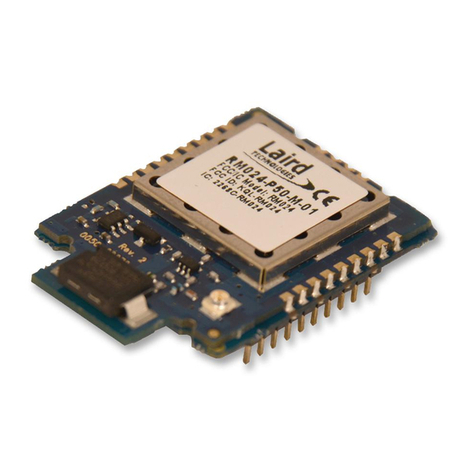
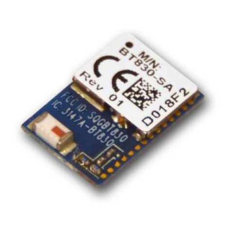
Ublox NINA-B3 Series Quick setup guide

NINA-B3 series - System integration manual
UBX-17056748 - R13 Document information Page 2 of 72
C1-Public
Document information
Title
NINA-B3 series
Subtitle
Stand-alone Bluetooth 5 low energy modules
Document type
System integration manual
Document number
UBX-17056748
Revision and date
R13
14-Jan-2022
Disclosure restriction
C1-Public
Document status descriptions
Draft
For functional testing. Revised and supplementary data will be published later.
Objective specification
Target values. Revised and supplementary data will be published later.
Advance information
Data based on early testing. Revised and supplementary data will be published later.
Early production information
Data from product verification. Revised and supplementary data may be published later.
Production information
Document contains the final product specification.
This document applies to the following products:
Open CPU:
Product name
Document status
Comment
NINA-B301
Early Production Information
NINA-B302
Early Production Information
NINA-B306
Early Production Information
NINA-B306-01B is without external LFXO.
u-connectXpress:
Product name
Document status
Comment
NINA-B311
Early Production Information
NINA-B312
Early Production Information
NINA-B316
Early Production Information
☞For information about the related hardware, software, and status of listed product types, see the
respective data sheets.
u-blox or third parties may hold intellectual property rights in the products, names, logos and designs included in this
document. Copying, reproduction, modification or disclosure to third parties of this document or any part thereof is only
permitted with the express written permission of u-blox.
The information contained herein is provided “as is” and u-blox assumes no liability for its use. No warranty, either express or
implied, is given, including but not limited to, with respect to the accuracy, correctness, reliability and fitness for a particular
purpose of the information. This document may be revised by u-blox at any time without notice. For the most recent
documents, visit www.u-blox.com.
Copyright © u-blox AG.

NINA-B3 series - System integration manual
UBX-17056748 - R13 Contents Page 3 of 72
C1-Public
Contents
Document information................................................................................................................................2
Contents ..........................................................................................................................................................3
1System description...............................................................................................................................6
1.1 Overview and applications ........................................................................................................................6
1.2 Architecture .................................................................................................................................................8
1.2.1 Block diagrams.................................................................................................................................... 8
1.2.2 Hardware options ...............................................................................................................................8
1.2.3 Software options ................................................................................................................................8
1.3 Pin configuration and function.................................................................................................................9
1.4 Supply interfaces ........................................................................................................................................ 9
1.4.1 Main supply input ...............................................................................................................................9
1.4.2 Digital I/O interfaces reference voltage (VCC_IO) ........................................................................9
1.4.3 VCC application circuits ....................................................................................................................9
1.5 System function interfaces ....................................................................................................................10
1.5.1 Module reset ......................................................................................................................................10
1.5.2 Internal temperature sensor ..........................................................................................................10
1.6 Debug –Serial Wire Debug (SWD) .........................................................................................................10
1.7 Serial interfaces ........................................................................................................................................10
1.7.1 Universal Asynchronous Serial Interface (UART) ......................................................................10
1.7.2 Serial Peripheral Interface (SPI).....................................................................................................11
1.7.3 Quad serial peripheral interface (QSPI)........................................................................................11
1.7.4 I2C interface.......................................................................................................................................12
1.7.5 USB 2.0 interface..............................................................................................................................12
1.8 GPIO pins.....................................................................................................................................................12
1.8.1 Analog interfaces..............................................................................................................................13
1.9 Antenna interfaces...................................................................................................................................14
1.9.1 Antenna pin –NINA-B3x1................................................................................................................14
1.9.2 Integrated antenna –NINA-B3x2/B3x6........................................................................................15
1.9.3 NFC antenna......................................................................................................................................15
1.10 Reserved pins (RSVD) ..............................................................................................................................15
1.11 GND pins .....................................................................................................................................................15
2Software ................................................................................................................................................ 16
2.1 u-connectXpress software......................................................................................................................16
2.2 Open CPU....................................................................................................................................................17
2.2.1 Nordic nRF5 SDK ..............................................................................................................................17
2.2.2 Zephyr .................................................................................................................................................21
2.2.3 Saving Bluetooth MAC address and other production data....................................................22
2.2.4 Support –Nordic development forum ..........................................................................................23
2.3 Updating NINA-B31 software.................................................................................................................23
2.3.1 Updating over UART.........................................................................................................................23

NINA-B3 series - System integration manual
UBX-17056748 - R13 Contents Page 4 of 72
C1-Public
2.4 Flashing NINA-B30 open CPU software ...............................................................................................31
2.4.1 Flashing over the SWD interface...................................................................................................31
3Design-in................................................................................................................................................ 32
3.1 Overview......................................................................................................................................................32
3.2 Design for NINA family.............................................................................................................................32
3.3 Antenna interface .....................................................................................................................................32
3.3.1 RF transmission line design (NINA-B3x1 only)...........................................................................33
3.3.2 Antenna design (NINA-B3x1 only).................................................................................................34
3.3.3 On-board antenna.............................................................................................................................37
3.4 Supply interfaces ......................................................................................................................................39
3.4.1 Module supply design ......................................................................................................................39
3.5 Serial interfaces ........................................................................................................................................40
3.5.1 Asynchronous serial interface (UART) design............................................................................40
3.5.2 Serial peripheral interface (SPI) .....................................................................................................40
3.5.3 I2C interface.......................................................................................................................................40
3.5.4 QSPI interface....................................................................................................................................40
3.5.5 USB interface.....................................................................................................................................40
3.6 NFC interface.............................................................................................................................................40
3.6.1 Battery protection ............................................................................................................................41
3.7 General High Speed layout guidelines ..................................................................................................41
3.7.1 General considerations for schematic design and PCB floor-planning .................................41
3.7.2 Module placement ............................................................................................................................42
3.7.3 Layout and manufacturing.............................................................................................................42
3.8 Module footprint and paste mask .........................................................................................................42
3.9 Thermal guidelines ...................................................................................................................................43
3.10 ESD guidelines ...........................................................................................................................................43
4Handling and soldering ..................................................................................................................... 44
4.1 ESD handling precautions.......................................................................................................................44
4.2 Packaging, shipping, storage, and moisture preconditioning .........................................................44
4.3 Soldering .....................................................................................................................................................44
4.3.1 Reflow soldering process ................................................................................................................45
4.3.2 Cleaning ..............................................................................................................................................46
4.3.3 Other remarks ...................................................................................................................................46
5Regulatory information and requirements ................................................................................ 47
5.1 ETSI –European market ..........................................................................................................................47
5.1.1 Compliance statement....................................................................................................................47
5.1.2 NINA-B3 Software security considerations ................................................................................47
5.1.3 Output power limitation ..................................................................................................................47
5.1.4 Safety Compliance ...........................................................................................................................48
5.2 FCC/ISED –US/Canadian markets ........................................................................................................49
5.2.1 Compliance statements..................................................................................................................49
5.2.2 RF Exposure .......................................................................................................................................49

NINA-B3 series - System integration manual
UBX-17056748 - R13 Contents Page 5 of 72
C1-Public
5.2.3 Antenna selection.............................................................................................................................50
5.2.4 IEEE 802.15.4 channel map limitation .........................................................................................50
5.2.5 Change in ID/Multiple Listing process..........................................................................................50
5.2.6 End product verification requirements ........................................................................................51
5.2.7 End product labelling requirements .............................................................................................51
5.2.8 End product user manual requirements ......................................................................................52
5.3 MIC - Japanese market............................................................................................................................53
5.3.1 Compliance statement....................................................................................................................53
5.3.2 48-bit address requirement ...........................................................................................................53
5.3.3 End product labelling requirement................................................................................................54
5.3.4 End product user manual requirement ........................................................................................54
5.4 NCC –Taiwanese market ........................................................................................................................54
5.4.1 Compliance statements..................................................................................................................54
5.4.2 End product labelling requirement................................................................................................55
5.5 KCC –South Korean market ...................................................................................................................56
5.5.1 Compliance statement....................................................................................................................56
5.5.2 End product labeling requirements ..............................................................................................56
5.5.3 End product user manual requirements ......................................................................................57
5.6 Anatel Brazil compliance .........................................................................................................................57
5.7 Australia and New Zealand regulatory compliance ...........................................................................57
5.8 South Africa regulatory compliance .....................................................................................................58
5.9 Integration checklist ................................................................................................................................58
5.10 Pre-approved antennas list.....................................................................................................................59
5.10.1 Antenna accessories........................................................................................................................60
5.10.2 Single band antennas ......................................................................................................................60
6Product testing ................................................................................................................................... 63
6.1 u-blox in-line production testing ............................................................................................................63
6.2 OEM manufacturer production test .....................................................................................................64
6.2.1 “Go/No go” tests for integrated devices ......................................................................................64
Appendix ....................................................................................................................................................... 65
AGlossary ................................................................................................................................................. 65
BAntenna reference designs ............................................................................................................. 67
B.1 Reference design for external antennas (U.FL connector)................................................... 67
B.1.1 Floor plan ...................................................................................................................................... 68
B.1.2 RF trace specification............................................................................................................... 68
Related documents ................................................................................................................................... 70
Revision history.......................................................................................................................................... 71
Contact.......................................................................................................................................................... 72

NINA-B3 series - System integration manual
UBX-17056748 - R13 System description Page 6 of 72
C1-Public
1System description
1.1 Overview and applications
NINA-B3 series modules are small stand-alone Bluetooth 5 low energy microcontroller units (MCU)
that feature full Bluetooth 5, a powerful Arm®Cortex®-M4 with FPU, and state-of-the-art power
performance. The embedded low power crystal in the NINA-B3 series improves power consumption
by enabling optimal power save modes.
NINA-B3x2 comes with an internal antenna, while the NINA-B3x1 has a pin for use with an external
antenna. The internal PIFA antenna is specifically designed for the small NINA form factor and
provides an extensive range. The NINA-B3 series is globally certified for use with the internal antenna
or a range of external antennas. This greatly reduces time, cost, and effort for customers integrating
the NINA-B3 in their designs.
The NINA-B3 series includes the following two sub-series as listed in the table below:
Model
Description
NINA-B30 series
Bluetooth 5 module with a powerful Arm Cortex-M4 with FPU, and state-of-the-art power performance.
Both the variants of NINA-B30 are open CPU modules that enable customer applications to run on the
built-in Arm Cortex-M4 with FPU. With 1 MB flash and 256 kB RAM, they offer the best-in-class capacity
for customer applications on top of the Bluetooth low energy stack.
NINA-B301 has a pin for use with an external antenna, NINA-B302 comes with an internal PIFA antenna,
and NINA-B306 has an internal PCB antenna integrated in the module PCB. The internal antennas are
specifically designed for the small NINA form factor and provides an extensive range.
The NINA-B306-01B module variant comes without the LFXO (Low frequency crystal oscillator) mounted.
NINA-B31 series
Bluetooth 5 module with a powerful Arm Cortex-M4 with FPU and u-connectXpress software pre-flashed.
The software in NINA-B31 modules provides support for u-blox Bluetooth low energy Serial Port Service,
GATT client and server, beacons, NFC™, and simultaneous peripheral and central roles –all configurable
from a host using AT commands. The NINA-B31x modules provide top grade security, thanks to secure
boot, which ensures the module only boots up with original u-blox software.
NINA-B311 has a pin for use with an external antenna, NINA-B312 comes with an internal PIFA antenna,
and NINA-B316 has an internal PCB antenna integrated in the module PCB. The internal antennas are
specifically designed for the small NINA form factor and provides an extensive range.

NINA-B3 series - System integration manual
UBX-17056748 - R13 System description Page 8 of 72
C1-Public
1.2 Architecture
1.2.1 Block diagrams
Figure 1 shows the block diagram of the NINA-B3 series. The 32.768 kHz crystal not part of
NINA-B306-01B.
Figure 1: Block diagram of the NINA-B3 series
1.2.2 Hardware options
NINA-B3 series modules use an identical hardware configuration except for the different PCB sizes
and antenna solutions. An on-board 32.768 kHz low power crystal is included in all variants except the
NINA-B306-01B. An integrated DC/DC converter for higher efficiency under heavy load situations is
also included.
1.2.3 Software options
NINA-B3 can be used either together with the pre-flashed u-connectXpress software or as an open
CPU module where you can run your own application developed with the Nordic SDK development
environment inside the NINA-B3 module. For further information about the various software options,
see Software.
The u-connectXpress software also, from SW 3.0.0, contains Bluetooth mesh functionality.
DC/DC and LDO regulators
1 MB flash
Bluetooth LE
baseband
Cryptographic
hardware
accelerators
IO buffers
Arm Cortex-M4
PIFA antenna
(NINA-B3x2)
PLL
VCC_IO (1.7 –3.6 V)
VCC (1.7 - 3.6 V)
32 MHz
Reset
UART
SPI
GPIO
1.3 V
System
power
I2C
PWM
I2S
ADC and
comparator
Analog
Passive NFC tag
NFC
256 kB
RAM
PLL
32.768 kHz
RTC, timers
and counters
RF
Antenna pin
NINA-B3x1
Nordic Semiconductor
nRF52840
QSPI
USB device
USB 2.0
QDEC
PDM
CryptoCell
(NINA-B3x6)
PCB trace antenna

NINA-B3 series - System integration manual
UBX-17056748 - R13 System description Page 9 of 72
C1-Public
1.3 Pin configuration and function
See the NINA-B3 series data sheet [2] for information about pin configuration and function.
1.4 Supply interfaces
1.4.1 Main supply input
The NINA-B3 series uses an integrated DC/DC converter to transform the supply voltage presented
at the VCC pin into a stable system core voltage. Because of this, the NINA-B3 modules are
compatible for use in battery powered designs.
When using the NINA-B3 with a battery, it is important that the battery type can handle the peak
power of the module. For the battery supply, consider adding extra capacitance on the supply line to
avoid capacity degradation. See the NINA-B3 series data sheet [2] for information about voltage
supply requirements and current consumption.
Table 2: Summary of voltage supply requirements
☞The current requirement in Table 2 considers using the u-connectXpress software with UART
communications. But it does not include any additional I/O current. Any use of external push
buttons, LEDs, or other interfaces will add to the total current consumption of the NINA-B3
module. The peak current consumption of the entire design will need to be taken into account
when considering a battery powered solution.
1.4.2 Digital I/O interfaces reference voltage (VCC_IO)
On NINA-B3 series modules, the I/O voltage level is the same as the supply voltage and VCC_IO is
internally connected to the supply input VCC.
When using NINA-B3 with a battery, the I/O voltage level will vary with the battery output voltage,
depending on the charge of the battery. Level shifters might be needed depending on the I/O voltage
of the host system.
1.4.3 VCC application circuits
The power for NINA-B3 series modules is provided through the VCC pins, which can be one of the
following:
•Switching Mode Power Supply (SMPS)
•Low Drop Out (LDO) regulator
•Battery
The SMPS is the ideal choice when the available primary supply source has a higher value than the
operating supply voltage of the NINA-B3 series modules. The use of SMPS provides the best power
efficiency for the overall application and minimizes the current drawn from the main supply source.
⚠While selecting SMPS, ensure that the AC voltage ripple at the switching frequency is kept as low
as possible. Layout shall be implemented to minimize impact of high frequency ringing.
The use of an LDO linear regulator is convenient for a primary supply with a relatively low voltage
where the typical 85-90% efficiency of the switching regulator leads to minimal current saving. Linear
regulators are not recommended for high voltage step-down, as these dissipate a considerable
amount of energy.
Rail
Voltage requirement
Current requirement (peak)
VCC
1.7 V –3.6 V
20 mA
VCC_IO
Tied to VCC

NINA-B3 series - System integration manual
UBX-17056748 - R13 System description Page 10 of 72
C1-Public
DC/DC efficiency should be evaluated as a tradeoff between active and idle duty cycles of the specific
application. Although some DC/DC can achieve high efficiency at extremely light loads, a typical
DC/DC efficiency quickly degrades as idle current drops below a few mA, greatly reducing the battery
life.
Due to the low current consumption and wide voltage range of the NINA-B3 series module, a battery
can be used as a main supply. The capacity of the battery should be selected to match the application.
Care should be taken so that the battery can deliver the peak current required by the module. See the
NINA-B3 series data sheet [2] for the electrical specifications.
It is best practice to include decoupling capacitors on the supply rails close to the NINA-B3 series
module. But depending on the design of the power routing on the host system, capacitance might not
be needed.
1.5 System function interfaces
1.5.1 Module reset
You can reset NINA-B3 modules by applying a low level on the RESET_N input pin, which is normally
set high with an internal pull-up. This causes an “external” or “hardware” reset of the module. The
current parameter settings are not saved in the non-volatile memory of the module and a proper
network detach is not performed.
1.5.2 Internal temperature sensor
The radio chip in NINA-B3 contains a temperature sensor used for over temperature and under
temperature shutdown.
⚠The temperature sensor is located inside the radio chip and should not be used if an accurate
temperature reading of the surrounding environment is required.
1.6 Debug –Serial Wire Debug (SWD)
The primary interface for debugging is the SWD interface. NINA-B30 series modules provide an SWD
interface for flashing and debugging. The two pins SWDIO and SWDCLK should be made accessible
on header or test points.
The SWD interface is disabled on the NINA-B31 series modules.
1.7 Serial interfaces
⚠As NINA B3 can be used with both the u-connectXpress and open CPU based applications, based
on the Nordic SDK, the available interfaces and the pin mapping may vary. For detailed pin
information, see Pin configuration and function.
1.7.1 Universal Asynchronous Serial Interface (UART)
NINA B3 provides a Universal Asynchronous Serial Interface (UART) for data communication.
The following UART signals are available:
•Data lines (RXD as input, TXD as output)
•Hardware flow control lines (CTS as input, RTS as output)
•DSR and DTS are used to set and indicate system modes

NINA-B3 series - System integration manual
UBX-17056748 - R13 System description Page 11 of 72
C1-Public
The UART can be used as both a 4-wire UART with hardware flow control and a 2-wire UART with only
TXD and RXD. If using the UART in 2-wire mode, CTS should be connected to GND on the
NINA-B3 module.
Depending on the bootloader used, the UART interface can also be used for software upgrades. See
also Software.
The u-connectXpress software adds the DSR and DTR pins to the UART interface. These pins are not
used as originally intended, but to control the state of the NINA-B3 module. Depending on the current
configuration, the DSR can be used to:
•Enter command mode
•Disconnect and/or toggle connectable status
•Enable/disable the rest of the UART interface
•Enter/wake up from the sleep mode
See the NINA-B3 series data sheet [2] for characteristics information about the UART interface.
Interface
Default configuration
COM port
115200 baud, 8 data bits, no parity, 1 stop bit, hardware flow control
Table 3: Default settings for the COM port while using the u-connectXpress software
It is recommended to make the UART available either as test points or connected to a header for a
software upgrade.
The I/O level of the UART will follow the VCC voltage and it can thus be in the range of 1.8 V and 3.6 V.
If you are connecting the NINA-B3 module to a host with a different voltage on the UART interface, a
level shifter should be used.
1.7.2 Serial Peripheral Interface (SPI)
NINA-B3 supports up to three serial peripheral interfaces that can operate in both master and slave
modes with a maximum serial clock frequency of 8 MHz in both these modes. The SPI interfaces use
the following signals:
•SCLK
•MOSI
•MISO
•CS
•DCX (Data/Command signal). This signal is optional but is sometimes used by the SPI slaves to
distinguish between SPI commands and data.
When using the SPI interface in master mode, it is possible to use GPIOs as additional Chip Select (CS)
signals to allow addressing of multiple slaves.
1.7.3 Quad serial peripheral interface (QSPI)
The Quad Serial Peripheral Interface enables connection of external memory to the NINA-B3 module
in order to increase the application program size. The QSPI uses the following signals:
•CLK, serial clock output, up to 32 MHz
•CS, Chip/Slave select output, active low, selects which slave on the bus to talk to
•D0, MOSI serial output data in single mode, data I/O signal in dual/quad mode
•D1, MISO serial input data in single mode, data I/O signal in dual/quad mode
•D2, data I/O signal in quad mode (optional)
•D3, data I/O signal in quad mode (optional)

NINA-B3 series - System integration manual
UBX-17056748 - R13 System description Page 12 of 72
C1-Public
1.7.4 I2C interface
The Inter-Integrated Circuit (I2C) interfaces can be used to transfer or receive data on a 2-wire bus
network. NINA-B3 can operate as both Central and Peripheral on the I2C bus using both standard
(100 kbps) and fast (400 kbps) transmission speeds. The interface uses the SCL signal to clock
instructions and data on the SDA signal.
External pull-up resistors are required for the I2C interface. The value of the pull-up resistor should be
selected depending on the speed and capacitance of the bus. See Electrical specifications in the
NINA-B3 series data sheet [2] for recommended resistor values.
1.7.5 USB 2.0 interface
The NINA-B3 series modules include a full speed Universal Serial Bus (USB) device interface compliant
with version 2.0 of the USB specification. The pin configuration of the USB interface is provided below:
•VBUS, 5 V supply input, required in order to use the interface
•USB_DP, USB_DM, differential data pair
The USB interface has a dedicated power supply that requires a 5 V supply voltage for the VBUS pin.
This allows the USB interface to be used even though the rest of the module might be battery powered
or supplied by a 1.8 V supply, etc.
1.8 GPIO pins
In an un-configured state, NINA-B3 modules have 38 GPIO pins and no analog or digital interfaces. All
interfaces or functions must be allocated to a GPIO pin before use. Eight of the 38 GPIO pins are analog
enabled, meaning that they can have an analog function allocated to them. In addition to the serial
interfaces, Table 5 shows the digital and analog functions that can be assigned to a GPIO pin.
Function
Description
Default
NINA-B3 pin
Configurable
GPIOs
General purpose input
Digital input with configurable pull-up, pull-down, edge detection
and interrupt generation
Any
General purpose output
Digital output with configurable drive strength, push-pull, open
collector, or open emitter output
Any
Pin disabled
Pin is disconnected from the input and output buffers.
All*
Any
Timer/ counter
High precision time measurement between two pulses/ Pulse
counting with interrupt/event generation
Any
Interrupt/ Event trigger
Interrupt/event trigger to software application/ Wake-up event
Any
HIGH/LOW/Toggle on event
Programmable digital level triggered by internal or external events
without CPU involvement
Any
ADC input
8/10/12/14-bit analog to digital converter
Any analog
Analog comparator input
Compare two voltages, capable of generating wake-up events and
interrupts
Any analog
PWM output
Output simple or complex pulse width modulation waveforms
Any
Connection status indicator
Indicates if a BLE connection is maintained
BLUE**
Any
* = If left unconfigured ** = If using u-connectXpress software
Table 4: GPIO custom functions configuration

NINA-B3 series - System integration manual
UBX-17056748 - R13 System description Page 13 of 72
C1-Public
1.8.1 Analog interfaces
Eight out of the 38 digital GPIOs can be multiplexed to analog functions. The following analog
functions are available for use:
•1x 8-channel ADC
•1x Analog comparator*
•1x Low-power analog comparator*
*Only one of the comparators can be used simultaneously.
ADC
The Analog to Digital Converter (ADC) can sample up to 200 kHz using different inputs as sample
triggers. Both one-shot conversion and continuous sampling are supported. Table 5 shows the
sample speed in correlation to the maximum source impedance. It supports 8/10/12-bit resolution.
The ADC includes 14-bit resolution if oversampling is used. Any of the 8 analog inputs can be used
both as single-ended inputs and as differential pairs for measuring the voltage across them.
The ADC supports the full 0 V to VCC input range. If the sampled signal level is much lower than VCC,
it is possible to lower the input range of the ADC to encompass the desired signal and obtain a higher
effective resolution. Continuous sampling can be configured to sample at a configurable time interval,
or at different internal or external events, without CPU involvement.
Table 5: Acquisition vs. source impedance
Comparator
The comparator compares voltages from any analog pin with different references as shown in Table
6. It supports the full 0 V to VCC input range and can generate different software events to the rest
of the system. The comparator can operate in the one of the following two modes as explained below
- Single-ended or Differential:
•Single-ended Mode: A single reference level or an upper and lower hysteresis selectable from a
64-level reference ladder with a range from 0 V to VREF as described in Table 6.
•Differential Mode: Two analog pin voltage levels are compared, optionally with a 50 mV hysteresis
Low power comparator
The low-power comparator operates in the same way as the normal comparator, with reduced
functionality. It can be used during system OFF modes as a wake-up source.
Analog pin options
Table 6 shows the supported connections of the analog functions.
☞An analog pin may not be simultaneously connected to multiple functions.
ACQ [us]
Maximum source resistance [kΩ]
3
10
5
40
10
100
15
200
20
400
40
800

NINA-B3 series - System integration manual
UBX-17056748 - R13 System description Page 14 of 72
C1-Public
Symbol
Analog function
Connects to
ADCP
ADC single-ended or differential positive input
Any analog pin or VCC
ADCN
ADC differential negative input
Any analog pin or VCC
VIN+
Comparator input
Any analog pin
VREF
Comparator single-ended mode reference
ladder input
Any analog pin, VCC, 1.2 V, 1.8V or 2.4V
VIN-
Comparator differential mode negative input
Any analog pin
LP_VIN+
Low-power comparator IN+
Any analog pin
LP_VIN-
Low-power comparator IN-
GPIO_16 or GPIO_18, 1/16 to 15/16 VCC in steps of 1/16 VCC
Table 6: Possible uses of the analog pin
1.9 Antenna interfaces
☞The antenna interface is different for each module variant in the NINA-B3 series.
1.9.1 Antenna pin –NINA-B3x1
NINA-B3x1 is equipped with an RF pin. The RF pin has a nominal characteristic impedance of 50 Ωand
must be connected to the antenna through a 50 Ωtransmission line to allow reception of radio
frequency (RF) signals in the 2.4 GHz frequency band.
Choose an antenna with optimal radiating characteristics for the best electrical performance and
overall module functionality. An internal antenna integrated on the application board or an external
antenna that is connected to the application board through a proper 50 Ωconnector can be used.
While using an external antenna, the PCB-to-RF-cable transition must be implemented using either a
suitable 50 Ωconnector, or an RF-signal solder pad (including GND) that is optimized for 50 Ω
characteristic impedance.
Antenna matching
For optimal performance, the antenna return loss should be as good as possible across the entire
band when the system is operational. The enclosure, shields, other components and surrounding
environment will impact the return loss seen at the antenna port. Matching components are often
required to re-tune the antenna to bring the return loss within an acceptable range.
It is difficult to predict the actual matching values for the antenna in the final form factor. Therefore,
it is a good practice to have a placeholder in the circuit with a “pi” network, with two shunt components
and a series component in the middle, to allow maximum flexibility while tuning the matching to the
antenna feed.
Approved antenna designs
NINA-B3 modules come with a pre-certified design that can be used to save costs and time during the
certification process. To take advantage of this service, the customer is required to implement an
antenna layout according to the u-blox Antenna reference designs.
The designer integrating a u-blox reference design into an end-product is solely responsible for the
unintentional emission levels produced by the end product.
The module may be integrated with other antennas. In this case, the OEM installer must certify his
design with the respective regulatory agencies.

NINA-B3 series - System integration manual
UBX-17056748 - R13 System description Page 15 of 72
C1-Public
1.9.2 Integrated antenna –NINA-B3x2/B3x6
NINA-B3x2 and NINA-B3x6 modules are equipped with an integrated antenna on the module. This
simplifies the integration, as there is no need to do an RF trace design on the host PCB. By using
NINA-B3x2 or NINA-B3x6, the certification of NINA-B3 series modules can be reused, thus minimizing
the effort needed in the test lab. NINA-B3x2 modules use an internal metal sheet PIFA antenna, while
the NINA-B3x6 modules have a PCB trace antenna that uses antenna technology licensed from
Proant AB.
1.9.3 NFC antenna
NINA-B3 series modules include a Near Field Communication interface, capable of operating as a
13.56 MHz NFC tag at a bit rate of 106 kbps. As an NFC tag, data can be read from or written to the
NINA-B3 modules using an NFC reader; however, the NINA-B3 modules are not capable of reading
other tags or initiating NFC communications. Two pins are available for connecting to an external NFC
antenna: NFC1 and NFC2.
1.10 Reserved pins (RSVD)
Do not connect the reserved (RSVD) pin. The reserved pins are allocated for future interfaces and
functionality.
1.11 GND pins
Good connection of the module's GND pins with a solid ground layer of the host application board is
required for correct RF performance. It significantly reduces EMC issues and provides a thermal heat
sink for the module.
For information about ground design, see also Module footprint and paste mask and Thermal
guidelines.

NINA-B3 series - System integration manual
UBX-17056748 - R13 Software Page 16 of 72
C1-Public
2Software
NINA-B3 series modules can be used either with the pre-flashed u-connectXpress software, or as an
open CPU module in which you can run your own application developed with the Nordic SDK
development environment inside the NINA-B3 module.
The software on the NINA-B3 module contains the following parts:
•SoftDevice S140 is a Bluetooth® Low Energy (LE) central and peripheral protocol stack solution
•Optional bootloader
•Application
Figure 2: NINA-B3 software structure and available software options
2.1 u-connectXpress software
NINA-B31 series modules are delivered with the u-blox secure boot loader and pre-flashed
u-connectXpress software.
The u-connectXpress software enables use of the Bluetooth Low Energy functions, controlled by
AT commands over the UART interface. Some of the supported features include the u-blox Low
Energy Serial Port Service, GATT server and client, central and peripheral roles, and multidrop
connections.
For information about the features, capabilities, and use of u-connectXpress software, see the
u-connectXpress user guide [16] and u-connectXpress AT commands manual [4].
The u-connectXpress software on NINA-B3 is also (as of version 3.0.0) Bluetooth-mesh enabled. For
more information about the mesh software, see the Implementing Bluetooth mesh with
u-connectXpress software application note [24].
NINA-B3 Software
structure
Bootloader
Radio Stack
Application
NINA-B31 series
Nordic S140 SoftDevice
Nordic SDK
NINA-B30 series
u-connectXpress

NINA-B3 series - System integration manual
UBX-17056748 - R13 Software Page 17 of 72
C1-Public
2.2 Open CPU
2.2.1 Nordic nRF5 SDK
The Nordic nRF5 SDK includes a broad selection of drivers and libraries and provides a rich
development environment for various devices and applications. The SDK is delivered as a plain zip
archive, which makes it easy to install. The SDK comes with support for the SEGGER Embedded
Studio, Keil and IAR IDEs, as well as the GCC compiler, which offers the freedom to choose the IDE and
compiler.
Getting started on the Nordic nRF5 SDK
When working with the Nordic SDK on the NINA-B3 series module, follow the steps below to get
started with the Nordic Semiconductor toolchain and examples:
1. Download and install the nRF Connect application and install the Programmer app, which allows
programming over SWD, from www.nordicsemi.com.
2. Download and install the latest SEGGER Embedded Studio from www.segger.com.
3. Download and extract the latest nRF5 SDK found on
http://www.nordicsemi.com/eng/Products/Bluetooth-low-energy/nRF5-SDK to the directory that
you want to use to work with the nRF5 SDK.
4. Read the information in the SDK Release Notes and check the nRF5 software development kit
documentation available at the Nordic Semiconductor Infocenter [14].
The easiest way to get started with the Nordic SDK is to copy one of the examples in the SDK. Choose
an example that best matches your needs and use the board definition that is most like your board. If
you are building for NINA-B3 the closest board definition is the
pca10056.
Create a custom board for Nordic SDK
The predefined hardware boards included in the Nordic SDK are Nordic development boards only. To
add support for a custom board, create a custom board support file called custom_board.h. This file is
normally located in the folder …\components\boards\ or included together with the sdk_config.h file in
the config folder of the example.
The custom board can then be selected by adding the define statement #define BOARD_CUSTOM.
☞The referenced file location is in accordance with Nordic nRF5 SDK version 17.0.
Figure 3shows an example of how the custom board support file might look like for EVK-NINA-B3.
#ifndef CUSTOM_BOARD_H
#define CUSTOM_BOARD_H
#ifdef __cplusplus
extern "C" {
#endif
#include "nrf_gpio.h"
// In this file PIN 25 is used as button SWITCH_1, if the GREEN led
// should be used it is possible to defined that one instead.
#define LEDS_NUMBER 2
#define LED_1 NRF_GPIO_PIN_MAP(0,13) // RED
#define LED_2 NRF_GPIO_PIN_MAP(1,00) // BLUE
// #define LED_3 NRF_GPIO_PIN_MAP(0,25) // GREEN
#define LEDS_ACTIVE_STATE 0

NINA-B3 series - System integration manual
UBX-17056748 - R13 Software Page 18 of 72
C1-Public
#define LEDS_LIST { LED_1, LED_2 }
#define LEDS_INV_MASK LEDS_MASK
#define BSP_LED_0 LED_1
#define BSP_LED_1 LED_2
// #define BSP_LED_2 LED_3
#define BUTTONS_NUMBER 2
#define BUTTON_1 25 // SWITCH_1
#define BUTTON_2 2 // SWITCH_2
#define BUTTON_PULL NRF_GPIO_PIN_PULLUP
#define BUTTONS_ACTIVE_STATE 0
#define BUTTONS_LIST { BUTTON_1, BUTTON_2 }
#define BSP_BUTTON_0 BUTTON_1
#define BSP_BUTTON_1 BUTTON_2
#define RX_PIN_NUMBER NRF_GPIO_PIN_MAP(0,29)
#define TX_PIN_NUMBER NRF_GPIO_PIN_MAP(1,13)
#define CTS_PIN_NUMBER NRF_GPIO_PIN_MAP(1,12)
#define RTS_PIN_NUMBER NRF_GPIO_PIN_MAP(0,31)
#define HWFC true
#define BSP_QSPI_SCK_PIN 19
#define BSP_QSPI_CSN_PIN 17
#define BSP_QSPI_IO0_PIN 20
#define BSP_QSPI_IO1_PIN 21
#define BSP_QSPI_IO2_PIN 22
#define BSP_QSPI_IO3_PIN 23
// Arduino board mappings
#define ARDUINO_SCL_PIN 24 // SCL signal pin
#define ARDUINO_SDA_PIN 16 // SDA signal pin
#define ARDUINO_13_PIN NRF_GPIO_PIN_MAP(0, 7)
#define ARDUINO_12_PIN NRF_GPIO_PIN_MAP(0, 2)
#define ARDUINO_11_PIN NRF_GPIO_PIN_MAP(0, 15)
#define ARDUINO_10_PIN NRF_GPIO_PIN_MAP(0, 14)
#define ARDUINO_9_PIN NRF_GPIO_PIN_MAP(0, 12)
#define ARDUINO_8_PIN NRF_GPIO_PIN_MAP(1, 9)
#define ARDUINO_7_PIN NRF_GPIO_PIN_MAP(0, 10)
#define ARDUINO_6_PIN NRF_GPIO_PIN_MAP(0, 9)
#define ARDUINO_5_PIN NRF_GPIO_PIN_MAP(0, 11)
#define ARDUINO_4_PIN NRF_GPIO_PIN_MAP(0, 13)
#define ARDUINO_3_PIN NRF_GPIO_PIN_MAP(0, 31)
#define ARDUINO_2_PIN NRF_GPIO_PIN_MAP(1, 12)
#define ARDUINO_1_PIN NRF_GPIO_PIN_MAP(1, 13
#define ARDUINO_0_PIN NRF_GPIO_PIN_MAP(0, 29)
#define ARDUINO_A0_PIN NRF_GPIO_PIN_MAP(0, 4)
#define ARDUINO_A1_PIN NRF_GPIO_PIN_MAP(0, 30)
#define ARDUINO_A2_PIN NRF_GPIO_PIN_MAP(0, 5)
#define ARDUINO_A3_PIN NRF_GPIO_PIN_MAP(0, 2)
#define ARDUINO_A4_PIN NRF_GPIO_PIN_MAP(0, 28)
#define ARDUINO_A5_PIN NRF_GPIO_PIN_MAP(0, 3)
#define RASPBERRY_PI_3_PIN NRF_GPIO_PIN_MAP(0, 24)
#define RASPBERRY_PI_5_PIN NRF_GPIO_PIN_MAP(0, 16)
#define RASPBERRY_PI_7_PIN NRF_GPIO_PIN_MAP(0, 15)
#define RASPBERRY_PI_11_PIN NRF_GPIO_PIN_MAP(0, 14)
#define RASPBERRY_PI_13_PIN NRF_GPIO_PIN_MAP(0, 19)

NINA-B3 series - System integration manual
UBX-17056748 - R13 Software Page 19 of 72
C1-Public
#define RASPBERRY_PI_15_PIN NRF_GPIO_PIN_MAP(0, 17)
#define RASPBERRY_PI_19_PIN NRF_GPIO_PIN_MAP(0, 21)
#define RASPBERRY_PI_21_PIN NRF_GPIO_PIN_MAP(0, 23)
#define RASPBERRY_PI_23_PIN NRF_GPIO_PIN_MAP(0, 7)
#define RASPBERRY_PI_27_PIN NRF_GPIO_PIN_MAP(0, 26)
#define RASPBERRY_PI_29_PIN NRF_GPIO_PIN_MAP(1, 15)
#define RASPBERRY_PI_31_PIN NRF_GPIO_PIN_MAP(1, 11)
#define RASPBERRY_PI_33_PIN NRF_GPIO_PIN_MAP(1, 3)
#define RASPBERRY_PI_35_PIN NRF_GPIO_PIN_MAP(1, 2)
#define RASPBERRY_PI_37_PIN NRF_GPIO_PIN_MAP(1, 8)
#define RASPBERRY_PI_8_PIN RX_PIN_NUMBER
#define RASPBERRY_PI_10_PIN TX_PIN_NUMBER
#define RASPBERRY_PI_12_PIN NRF_GPIO_PIN_MAP(0, 13)
#define RASPBERRY_PI_16_PIN NRF_GPIO_PIN_MAP(0, 20)
#define RASPBERRY_PI_18_PIN NRF_GPIO_PIN_MAP(0, 22)
#define RASPBERRY_PI_22_PIN NRF_GPIO_PIN_MAP(0, 12)
#define RASPBERRY_PI_24_PIN NRF_GPIO_PIN_MAP(0, 27)
#define RASPBERRY_PI_26_PIN NRF_GPIO_PIN_MAP(0, 6)
#define RASPBERRY_PI_28_PIN NRF_GPIO_PIN_MAP(1, 14)
#define RASPBERRY_PI_32_PIN NRF_GPIO_PIN_MAP(1, 10)
#define RASPBERRY_PI_36_PIN NRF_GPIO_PIN_MAP(1, 1)
#define RASPBERRY_PI_38_PIN NRF_GPIO_PIN_MAP(1, 9)
#define RASPBERRY_PI_40_PIN NRF_GPIO_PIN_MAP(0, 11)
#ifdef __cplusplus
}
#endif
#endif // CUSTOM_BOARD_H
Figure 3: Example of EVK-NINA-B3 custom board support file
The board file can also be downloaded from the u-blox shortrange open CPU github repository [20].
To make the build system use your custom board file define the build variable BOARD_CUSTOM in the
build configuration. If you build on an existing example, undefine the default BOARD_PCA10056.
Adding a board configuration to your project
A flexible way of adding a board to your project is to add a new build configuration to your Segger
Studio project and then use this configuration to select the correct board file for your build. By adding
several configurations, you can build for several targets from the same Segger Studio project.

NINA-B3 series - System integration manual
UBX-17056748 - R13 Software Page 20 of 72
C1-Public
You can use the following procedure to build from both your custom board and u-blox EVK to test your
code on different platforms:
1. Add a build configuration in the Segger Studio project.
Figure 4 Add a build configuration to Segger Studio
2. Configure the build configuration to use your board definition. Assuming that you are basing your
project on an example from the Nordic nRF5 SDK, remember to undefine the configuration for the
original board.
Figure 5 Setting up board configuration to use evk_nina_b3.h board file
The build for your configuration now uses your custom board file.
This manual suits for next models
6
Table of contents
Other Ublox Wireless Module manuals

Ublox
Ublox MAX-M5Q Quick setup guide

Ublox
Ublox C94-M8P User manual

Ublox
Ublox LEON-G100 ECALL Quick setup guide

Ublox
Ublox EVK-R4 Series User manual

Ublox
Ublox LISA-U1 Series Quick setup guide

Ublox
Ublox C101-D9S User manual

Ublox
Ublox NORA-W30 Series Quick setup guide

Ublox
Ublox TOBY-R2 Series Quick setup guide

Ublox
Ublox NINA-W1 Series Quick setup guide

Ublox
Ublox NINA-B4 Series Quick setup guide