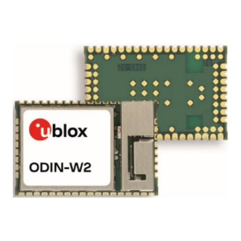
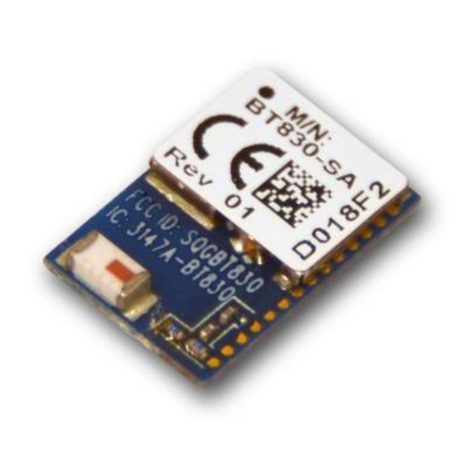
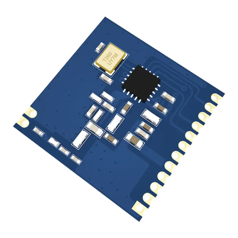
Ublox ODIN-W2 Series User manual

ODIN-W2 series
Stand-alone multiradio modules with
Wi-Fi & Bluetooth
Data Sheet
Abstract
This technical data sheet describes the ODIN-W2 series short range
multiradio modules with Wi-Fi and Bluetooth
dual mode 4.0
(Classic Bluetooth and Bluetooth Low Energy). The ODIN-
W2 is a
compact yet powerful stand-alone multiradio module designed for
Internet-of-Things applications in the compact ODIN form factor.
The Wi-Fi support conforms to IEEE 802.11a/b/g/n, and has support
for dual-band 2.4 GHz and 5 GHz operation and 2×2 MIMO (2.4
GHz).
www.u-blox.com
UBX-14039949 - R05

ODIN-W2 series - Data Sheet
UBX-14039949 - R05 Advance Information Contents
Page 2 of 36
Document Information
Title ODIN-W2 series
Subtitle Stand-alone multiradio modules with Wi-Fi & Bluetooth
Document type Data Sheet
Document number UBX-14039949
Revision and date R05 22-Sept-2015
Document status Advance Information
Document status explanation
Objective Specification Document contains target values. Revised and supplementary data will be published later.
Advance Information Document contains data based on early testing. Revised and supplementary data will be published later.
Early Production Information Document contains data from product verification. Revised and supplementary data may be published later.
Production Information Document contains the final product specification.
This document applies to the following products:
Product name Type number Firmware version PCN / IN reference
ODIN-W260 ODIN-W260-00B-00 1.0.0 TBD
ODIN-W262 ODIN-W262-00B-00 1.0.0 TBD
u-blox reserves all rights to this document and the information contained herein. Products, names, logos and designs described herein may in
whole or in part be subject to intellectual property rights. Reproduction, use, modification or disclosure to third parties of this document or
any part thereof without the express permission of u-blox is strictly prohibited.
The information contained herein is provided “as is” and u-blox assumes no liability for the use of the information. No warranty, either
express or implied, is given, including but not limited, with respect to the accuracy, correctness, reliability and fitness for a particular purpose
of the information. This document may be revised by u-blox at any time. For most recent documents, visit www.u-blox.com.
Copyright © 2015, u-blox AG.
u-blox® is a registered trademark of u-blox Holding AG in the EU and other countries. ARM® is the registered trademark of ARM Limited in
the EU and other countries.

ODIN-W2 series - Data Sheet
UBX-14039949 - R05 Advance Information Contents
Page 3 of 36
Contents
Contents..............................................................................................................................3
1Functional description..................................................................................................6
1.1 Overview .............................................................................................................................................. 6
1.2 Applications.......................................................................................................................................... 6
1.3 Product features ................................................................................................................................... 6
1.4 Block diagram....................................................................................................................................... 7
1.5 Product description............................................................................................................................... 7
1.6 AT command support........................................................................................................................... 8
1.7 IEEE 802.11d and additional regulatory domains .................................................................................. 8
1.7.1 ODIN-W2 IEEE 802.11d implementation description...................................................................... 8
2Interfaces ....................................................................................................................10
2.1 Power management ........................................................................................................................... 10
2.1.1 Module supply input (VCC) ......................................................................................................... 10
2.1.2 Digital I/O interfaces supply output (V_INT).................................................................................. 10
2.2 Antenna interfaces ............................................................................................................................. 10
2.2.1 Antenna connectors and internal antenna................................................................................... 10
2.3 Data communication interfaces .......................................................................................................... 11
2.3.1 UART interface ............................................................................................................................ 11
2.3.2 Ethernet interface........................................................................................................................ 11
3System functions ........................................................................................................13
3.1 Module power modes ........................................................................................................................ 13
3.2 Module reset ...................................................................................................................................... 13
3.3 System IO ........................................................................................................................................... 13
4Pin definition ..............................................................................................................14
4.1 Pin assignment ................................................................................................................................... 14
5Electrical specification................................................................................................17
5.1 Absolute maximum ratings ................................................................................................................. 17
5.1.1 Maximum ESD............................................................................................................................. 17
5.2 Operating conditions .......................................................................................................................... 17
5.2.1 Temperature range...................................................................................................................... 17
5.2.2 Power supply............................................................................................................................... 17
5.2.3 I/O DC characteristics .................................................................................................................. 18
5.2.4 Reset characteristics .................................................................................................................... 18
5.2.5 LPO clock .................................................................................................................................... 18
5.2.6 Universal asynchronous serial interface (UART) ............................................................................ 18
5.3 Power consumption............................................................................................................................ 19
5.3.1 General power consumption ....................................................................................................... 19

ODIN-W2 series - Data Sheet
UBX-14039949 - R05 Advance Information Contents
Page 4 of 36
5.3.2 Wi-Fi 2.4 GHz power consumption.............................................................................................. 19
5.3.3 Wi-Fi 5 GHz power consumption................................................................................................. 19
5.3.4 Classic Bluetooth power consumption......................................................................................... 20
5.3.5 Bluetooth Low Energy (BLE) power consumption......................................................................... 20
5.4 RF characteristics ................................................................................................................................ 20
5.4.1 Wi-Fi receiver characteristics 2.4 GHz .......................................................................................... 20
5.4.2 Wi-Fi receiver characteristics 5 GHz ............................................................................................. 21
5.4.3 Wi-Fi transmitter characteristics 2.4 GHz ..................................................................................... 21
5.4.4 Wi-Fi transmitter characteristics 5 GHz ........................................................................................ 21
5.4.5 Bluetooth Classic receiver characteristics ..................................................................................... 22
5.4.6 Bluetooth Low Energy receiver sensitivity..................................................................................... 22
5.4.7 Bluetooth Classic transmitter characteristics ................................................................................ 22
5.4.8 Bluetooth Low Energy transmitter characteristics......................................................................... 22
6Mechanical specifications ..........................................................................................23
6.1 Dimensions......................................................................................................................................... 23
6.2 Module weight ................................................................................................................................... 24
7Qualification and approvals ......................................................................................25
7.1 Compliance with RoHS directive ......................................................................................................... 25
7.2 Declaration of Conformity .................................................................................................................. 25
7.3 Safety Compliance.............................................................................................................................. 26
7.4 FCC and IC Compliance...................................................................................................................... 26
7.4.1 IC compliance.............................................................................................................................. 26
7.4.2 Conformité aux normes d’IC ....................................................................................................... 26
7.4.3 FCC statement ............................................................................................................................ 27
7.4.4 Labeling requirements for end product........................................................................................ 27
7.5 Japan radio equipment compliance..................................................................................................... 28
7.6 Bluetooth qualification information .................................................................................................... 29
8Product handling and soldering................................................................................30
8.1 Packaging........................................................................................................................................... 30
8.1.1 Reels ........................................................................................................................................... 30
8.1.2 Tapes .......................................................................................................................................... 30
8.2 Moisture sensitivity levels.................................................................................................................... 31
8.3 Reflow soldering................................................................................................................................. 31
8.4 ESD precautions.................................................................................................................................. 31
9Labeling and ordering information...........................................................................32
9.1 Product labeling.................................................................................................................................. 32
9.2 Explanation of codes........................................................................................................................... 33
9.3 Ordering information.......................................................................................................................... 33
Appendix ..........................................................................................................................34
ODIN-W2 series - Data Sheet
UBX-14039949 - R05 Advance Information Contents
Page 5 of 36
AGlossary ......................................................................................................................34
Related documents...........................................................................................................35
Revision history................................................................................................................35
Contact..............................................................................................................................36

ODIN-W2 series - Data Sheet
UBX-14039949 - R05 Advance Information Functional description
Page 6 of 36
1Functional description
1.1 Overview
The ODIN-W2 series is a highly integrated multiradio module developed by u-blox for integration in demanding,
reliable devices such as those needed for industrial and medical applications. The module is built around a
multiradio chip, which includes Wi-Fi, Classic Bluetooth and Bluetooth Low Energy (Dual Mode / Bluetooth Smart
Ready). The Wi-Fi support conforms to IEEE 802.11a/b/g/n, and has support for dual-band 2.4 GHz and 5 GHz
operation and 2.4 GHz 2×2 MIMO.
The high performance ODIN-W2 series module is available in different versions (see Product features). The
module has a small form factor and the interface layout is the same as previous Bluetooth and Wi-Fi modules
from u-blox in the 15x22 mm ODIN form factor.
The module is complete with embedded driver, stack and application for wireless data transfer and AT-command
configuration. The upcoming extensions of the module firmware include micro Access Point1and high speed
interfaces such as RMII for Ethernet applications.
1.2 Applications
•Internet of Things (IoT)
•Wi-Fi and Bluetooth networks
•Wi-Fi and Bluetooth access point
•Medical and industrial networking
•Access to laptops, mobile phones, and similar consumer devices
•Home/building automation
•Ethernet/Wireless Gateway
1.3 Product features
Table 1: Key features of ODIN-W2 series
1Planned for version 01B
2 Planned for version 02B
3Planned feature

ODIN-W2 series - Data Sheet
UBX-14039949 - R05 Advance Information Functional description
Page 7 of 36
1.4 Block diagram
The block diagram of the ODIN-W2 series is shown below:
Figure 1: Block diagram of ODIN-W2 series
1.5 Product description
The ODIN-W2 series module supports Wi-Fi, classic Bluetooth and Bluetooth Low Energy (dual mode / Bluetooth
Smart Ready). The Wi-Fi support conforms to IEEE 802.11a/b/g/n, and has support for dual-band 2.4 GHz and 5
GHz operation and 2×2 MIMO (2.4 GHz).
Wi-Fi Classic Bluetooth Bluetooth Low Energy
IEEE 802.11a/b/g/n***
ODIN-W260: 2X2 MIMO***(2.4GHz only)
Bluetooth 4.0, Classic Bluetooth +EDR
Maximum number of slaves: 7
Bluetooth profiles: SPP, DUN, GATT and PAN
Bluetooth 4.0 BLE dual mode
Band support
2.4 GHz, channel 1-13*
5 GHz, channel 36-165*
Band support
2.4 GHz, 79 channels
Band support
2.4 GHz, 40 channels
Maximum conducted output power
16 dBm / 19 dBm EIRP**
Maximum conducted output power
11 dBm / 14 dBm EIRP**
Maximum conducted output power
6.5 dBm / 9.5 dBm EIRP**
Conducted sensitivity
2.4 GHz: -94 dBm / -97 dBm EIRP**
5 GHz: -88 dBm / -91 dBm EIRP**
Conducted sensitivity
-90 dBm / -93 dBm EIRP**
Conducted sensitivity
-94 dBm / -97 dBm EIRP**
Data rates:
IEEE 802.11b:
1 / 2 / 5.5 / 11 Mbit/s
IEEE 802.11a/g:
6 / 9 / 12 / 18 / 24 / 36 / 48 / 54 Mbit/s
IEEE 802.11n SISO***:
6.5 / 13 / 19.5 / 26 / 39 / 52 / 58.5 / 65 Mbit/s
IEEE 802.11n 2x2 MIMO***:
13 / 26 / 39 / 52 / 78 / 104 / 117 / 130 Mbit/s
Data rates:
1 / 2 / 3 Mbit/s
Data rates:
1 Mbit/s
*Maximum, supports 802.11d and depends on region.
** RF power including maximum antenna gain (3 dBi).
*** Planned feature.
Table 2: ODIN-W2 series Wi-Fi and Bluetooth characteristics

ODIN-W2 series - Data Sheet
UBX-14039949 - R05 Advance Information Functional description
Page 8 of 36
1.6 AT command support
The ODIN-W2 series modules support AT commands as described in the ODIN-W2 AT Commands Manual [1].
See also the s-center software, which is an easy-to-use tool from u-blox for evaluating, and configuration of
u-blox Short Range modules. The s-center tool is available for download on the www.u-blox.com website.
1.7 IEEE 802.11d and additional regulatory domains
The ODIN-W2 series modules support IEEE 802.11d. IEEE 802.11d is an amendment to the IEEE 802.11
specification that adds support for "additional regulatory domains". IEEE 802.11d allows ODIN-W2 based
devices to self-configure and operate according to the regulations of the country in which they operate. Its
parameters include country name, channel quantity and maximum transmission level. The country information
feature simplifies the creation of 802.11 wireless access points and client devices that meet the different
regulations enforced in various parts of the world.
1.7.1 ODIN-W2 IEEE 802.11d implementation description
When ODIN-W2 is used as a Wi-Fi station, the scan is used to detect which regulatory domain it is currently in.
Passive scan is used for channels that are not available in all regulatory domains. The device supports the
following three domains, where WORLD means all channels that are supported both by FCC, ETSI and most
other countries in the world:
•WORLD
•FCC
•ETSI
See Table 3 for detailed information on channels that are supported in the different regulatory domains. The
state transition diagram below (Figure 2) describes the algorithm for selecting the current regulatory domain.
Figure 2: ODIN-W2 series IEEE 802.11d state transition diagram
Initial regulatory domain is WORLD. At start up a scan is initiated to detect beacons containing country
information IEs.
If at least one scan result contains country information indicating FCC and no country information indicates ETSI,
then the regulatory domain is set to FCC.
If at least two scan results contain country information indicating ETSI and no country information indicates FCC,
then the regulatory domain is set to ETSI.
WORLD
FCC
WORLD-FINAL
ETSI
Scan complete
FCC AP found and no ETSI AP found
Scan complete
ETSI found
Scan complete
Two or more ETSI AP found and
no FCC AP found
Scan complete
FCC found
Scan complete
No or both FCC and
ETSI AP found
Entry start scan
Do start scan every hour

ODIN-W2 series - Data Sheet
UBX-14039949 - R05 Advance Information Functional description
Page 9 of 36
If the scan result contains country information indicating both FCC and country information indicating ETSI, then
the regulatory domain is set to WORLD. In the state transition diagram this is the state WORLD_FINAL. This state
will not be exited until the device is reset.
A new scan is performed every hour to update the regulatory domain.
If the current regulatory domain is ETSI and at least one scan result contains country information indicating FCC
and then the regulatory domain is set to WORLD. In the state transition diagram this is the state WORLD-FINAL.
This state is will not be exited until the device is reset.
If the current regulatory domain is FCC and at least one scan result contains country information indicating ETSI
and then the regulatory domain is set to WORLD. In the state transition diagram this is the state WORLD-FINAL.
This state is will not be exited until the device is reset.
At restart of the device the algorithm is restarted. It is not possible to override the algorithm described by
reconfiguration the device.
Regulatory Domain Band Tx Channels
WORLD 2.4 GHz 1, 2, 3, 4, 5, 6, 7, 8, 9, 10, 11
U-NII-1 36, 40, 44, 48
U-NII-2 52, 56, 60, 64
U-NII-2e 100, 104, 108, 112, 116, 132, 136, 140
U-NII-3 -
ETSI 2.4 GHz 1, 2, 3, 4, 5, 6, 7, 8, 9, 10, 11, 12, 13
U-NII-1 36, 40, 44, 48
U-NII-2 52, 56, 60, 64
U-NII-2e 100, 104, 108, 112, 116, 120, 124, 128, 132, 136, 140
U-NII-3 149, 153, 157, 161, 165
FCC 2.4 GHz 1, 2, 3, 4, 5, 6, 7, 8, 9, 10, 11
U-NII-1 36, 40, 44, 48
U-NII-2 52, 56, 60, 64
U-NII-2e 100, 104, 108, 112, 116, 132, 136, 140
U-NII-3 149, 153, 157, 161, 165
Table 3: Channel list for supported regulatory domains
The maximum output power is reduced on some channels depending on regulatory requirements. For example,
frequency band edge requirements can limit the output power on channels close to band edges.

ODIN-W2 series - Data Sheet
UBX-14039949 - R05 Advance Information Interfaces
Page 10 of 36
2Interfaces
2.1 Power management
2.1.1 Module supply input (VCC)
The ODIN-W2 series modules must be supplied through the VCC pin by a DC power supply. Voltage must be
stable, because during operation the current drawn from VCC can vary significantly based on the power
consumption profile of the Bluetooth/Wi-Fi technologies.
2.1.2 Digital I/O interfaces supply output (V_INT)
The ODIN-W2 series modules provide a 1.8 V supply rail output on the V_INT pin, which is internally generated
when the module is powered on. The same voltage domain is used internally to supply the generic digital
interfaces of the modules. The V_INT supply output can be used instead of an external discrete regulator. See
the Electrical specification section for maximum output current.
2.2 Antenna interfaces
The following two different antenna options are available in the ODIN-W2 series:
•ODIN-W260 equipped with dual U.FL. coaxial connectors for external antennas. Different types of
external antennas are available and can be used.
•ODIN-W262 equipped with an integrated dual-band antenna
While mounting the unit, ensure that it does not interfere with radio communication. The ODIN-W262
equipped with an internal surface mounted antenna should not be mounted in a metal enclosure. No
metal casing or plastics using metal flakes should be used. Avoid metallic based paint or lacquer.
See ODIN-W2 series System Integration Manual [2] for information on the external antennas that can be used
and for other RF and antenna design advices.
2.2.1 Antenna connectors and internal antenna
The ODIN-W260 module has two RF antenna U.FL. coaxial connectors with a characteristic impedance of 50 Ω.
The main antenna connector supports both Bluetooth and dual-band Wi-Fi. The second (MIMO) antenna
connector adds support for 2x2 MIMO 2.4 GHz single band Wi-Fi.
The ODIN-W262 module has an internal dual-band PIFA antenna and supports Bluetooth and dual-band Wi-Fi
(SISO).

ODIN-W2 series - Data Sheet
UBX-14039949 - R05 Advance Information Interfaces
Page 11 of 36
Figure 3: ODIN-W260 with connectors for external antennas and the ODIN-W262 with an internal antenna
2.3 Data communication interfaces
The ODIN-W2 series provides several data communication interfaces which are described below.
2.3.1 UART interface
The ODIN-W2 series modules include a 6-wire UART for communication with an application host processor (AT
commands, Data communication and firmware upgrades).
The following UART signals are available:
•Data lines (RXD as input, TXD as output)
•Hardware flow control lines (CTS as input, RTS as output)
•Link status (DTR as output, DSR as input)
It is recommended to use CMOS compatible signal levels. See ODIN-W2 AT Commands Manual [1] and ODIN-
W2 series System Integration Manual [2] for more information about the UART interface.
2.3.2 Ethernet interface
Support for an Ethernet interface is planned for version ODIN-W26x-01B-00.
The ODIN-W2 series modules include an integrated Ethernet MAC to communicate with other networked nodes
over a shared medium. It supports 10/100 Mbit/s communication and can operate in both full- and half-duplex
(CSMA/CD).
The Ethernet interface includes:
•RMII either for MAC to PHY or Ethernet MAC to MAC communication.
•SMI for PHY configuration

ODIN-W2 series - Data Sheet
UBX-14039949 - R05 Advance Information Interfaces
Page 12 of 36
The IO voltage of the ODIN-W2 is 1.8 V, which means that the RMII interface operates outside the RMII
specification v1.2. If the RMII is to be connected to a PHY circuit, then that circuit must support 1.8 V
operation. If a direct RMII to RMII connection is used, then a level shifter might be needed depending on
the selected host. The selected hardware setup must be verified on the application board to guarantee
operation.
2.3.2.1 RMII
The RMII uses 7 signals in total. The interface requires an external 50 MHz clock source either from a compatible
PHY chip or an external oscillator. The ODIN-W2 module cannot provide this clock signal by itself.
2.3.2.2 SMI (MDC/MDIO management interface)
The two-wire SMI is used to configure the PHY chips. It uses a clock line and a data line to clock data to and
from the PHY chips registers.

ODIN-W2 series - Data Sheet
UBX-14039949 - R05 Advance Information System functions
Page 13 of 36
3System functions
3.1 Module power modes
Support for power save mode is available in version ODIN-W26x-01B-00.
The ODIN-W2 series module does not have an internal low power oscillator (LPO) which is required for low
power modes. An external 32.768 kHz LPO signal can be supplied externally via the LPO_CLK pin if low power
modes are required.
3.2 Module reset
The ODIN-W2 series modules can be reset (rebooted) in one of the following ways:
•Low level on the RESET_N pin, which is normally set high by an internal pull-up. This causes «hardware”
reset of the module. The RESET_N line should be driven by an open drain, open collector or contact
switch.
•Using a reset AT command (see the ODIN-W2 AT Commands Manual [1]). This causes «software” reset
of the module.
3.3 System IO
The module has the following six different configurable IOs that can be used to indicate different system states
or to be used as inputs, thus setting the module in different states:
•SWITCH_0
•RED
•GREEN/SWITCH_1
•BLUE
•UART_DTR
•UART_DSR
See the Pin definition section for more information on the separate IOs. For more information on the use and
configuration of the System IOs, see the ODIN-W2 AT Commands Manual [1].

ODIN-W2 series - Data Sheet
UBX-14039949 - R05 Advance Information Pin definition
Page 14 of 36
4Pin definition
4.1 Pin assignment
Figure 4: ODIN-W2 series pin assignment
The signals are available on castellation pads on the edge of the PCB. All non-filled round pads are GND pads.
Black circular pads are test and production points that should not be used. RSVD = Reserved, do not connect.

ODIN-W2 series - Data Sheet
UBX-14039949 - R05 Advance Information Pin definition
Page 15 of 36
No Name I/O Description Remarks
A1 RESET_N I External reset input. Internal active pull-up to V_INT.
A2 V_INT O Regulated output of the
internal I/O voltage.
1.8V, maximum output current 100mA. The maximum output
current can be limited by the internal current consumption of
the V_INT rail. See the Power consumption section.
A3 GND N/A Ground All GND pads must be connected to ground.
A4 VCC I Module power supply. 3.0 - 3.6 V power supply.
A5 UART_DTR O UART Data Terminal Ready. Active low.
Can also be used as a System IO.
See the System IO section for more information.
Also see the ODIN-W2 AT Commands Manual [1] for more
information about the pin functionality.
A6 SWITCH_0 I Connect on external signal. Active low.
A secondary function is that the module will restore all factory
settings if both the SWITCH_1 and SWITCH_0 signals are low
during start up.
See the ODIN-W2 AT Commands Manual [1] for more
information about the pin functionality.
A7 RED O Logic Red LED Signal. Active low.
See the System IO section for more information.
Also see the ODIN-W2 AT Commands Manual [1] for more
information about the pin functionality.
A8 GREEN/
SWITCH_1
O/I This signal is multiplexed:
GREEN: Logic Green LED
Signal.
SWITCH_1: Default Serial
Settings.
Active low.
The GREEN signal is not valid until 500ms after startup. See the
System IO section for more information.
If the level on this pin is pulled-down during start-up the unit
goes back to default serial settings. The SWITCH_1 input is only
active during the first 500ms after startup.
The module will restore all factory settings if both the SWITCH_1
and SWITCH_0 signals are low during start up.
Also see the ODIN-W2 AT Commands Manual [1] for more
information about the pin functionality.
A9 BLUE O Logic Blue LED Signal. Active low.
See the System IO section for more information.
Also see the ODIN-W2 AT Commands Manual [1] for more
information about the pin functionality.
A10 UART_CTS I UART Clear To Send,
Hardware flow control.
Active low.
A11 UART_TXD O UART Transmit.
A12 UART_RTS O UART Request To Send,
Hardware flow control.
Active low.
A13 UART_RXD I UART Receive.
A14 RSVD N/A Reserved pin. Leave unconnected.
A15 RSVD N/A Reserved pin. Leave unconnected.
A16 RSVD N/A Reserved pin. Leave unconnected.
A17 RSVD N/A Reserved pin. Leave unconnected.
A18 UART_DSR I UART Data Set Ready. Active low.
Can also be used as a System IO.
See the System IO section for more information.
Also see the ODIN-W2 AT Commands Manual [1] for more
information about the pin functionality.
B1 RSVD N/A Reserved pin. Leave unconnected.
B2 RSVD N/A Reserved pin. Leave unconnected.
B3 RSVD N/A Reserved pin. Leave unconnected.
B4 RSVD N/A Reserved pin. Leave unconnected.

ODIN-W2 series - Data Sheet
UBX-14039949 - R05 Advance Information Pin definition
Page 16 of 36
No Name I/O Description Remarks
B5 RSVD N/A Reserved pin. Leave unconnected.
B6 RSVD N/A Reserved pin. Leave unconnected.
B7 RSVD N/A Reserved pin. Leave unconnected.
B8 RSVD N/A Reserved pin. Leave unconnected.
C1 GND N/A Ground All GND pads must be connected to ground.
C2 RSVD N/A Reserved pin. Leave unconnected.
C3 GND N/A Ground All GND pads must be connected to ground.
C4 GND N/A Ground All GND pads must be connected to ground.
C5 RSVD N/A Reserved pin. Leave unconnected.
C6 RSVD N/A Reserved pin. Leave unconnected.
C7 GND N/A Ground All GND pads must be connected to ground.
C8 RSVD N/A Reserved pin. Leave unconnected.
C9 RSVD N/A Reserved pin. Leave unconnected.
C10 RSVD N/A Reserved pin. Leave unconnected.
C11 RSVD N/A Reserved pin. Leave unconnected.
C12 RSVD N/A Reserved pin. Leave unconnected.
C13 RSVD N/A Reserved pin. Leave unconnected.
C14 RMII_MDC O Management Interface Clock
output
According to RMII specification v1.2 with the exception that
voltage level is 1.8V.
C15 RMII_MDIO I/O Management Interface Data
I/O
An external pull-up resistor is required on the bidirectional data
signal.
According to RMII specification v1.2 with the exception that
voltage level is 1.8V.
C16 LPO_CLK I Low Power Oscillator clock
input
The module requires an external 32.768 kHz clock for low
power modes.
Leave this pin unconnected if not used as LPO clock input.
C17 RSVD N/A Reserved pin. Leave unconnected.
C18 RSVD N/A Reserved pin. Leave unconnected.
D1 RMII_TXD0 O Transmit Data output 0 According to RMII specification v1.2 with the exception that
voltage level is 1.8V.
D2 RMII_TXD1 O Transmit Data output 1 According to RMII specification v1.2 with the exception that
voltage level is 1.8V.
D3 RMII_TXEN O Transmit Enable output Active high.
According to RMII specification v1.2 with the exception that
voltage level is 1.8V.
D4 RMII_CRSDV I Carrier Sense/Receive Data
Valid input
Carrier Sense and Receive Data Valid signals are multiplexed
together, multiplexing scheme varies with implementation.
According to RMII specification v1.2 with the exception that
voltage level is 1.8V.
D5 RMII_RXD0 I Receive Data input 0 According to RMII specification v1.2 with the exception that
voltage level is 1.8V.
D6 RMII_RXD1 I Receive Data input 1 According to RMII specification v1.2 with the exception that
voltage level is 1.8V.
D7 GND N/A Ground All GND pads must be connected to ground.
D8 RMII_REFCLK I Reference Clock input Continuous 50 MHz reference clock input.
According to RMII specification v1.2 with the exception that
voltage level is 1.8V.
Table 4: ODIN-W2 series pin-out

ODIN-W2 series - Data Sheet
UBX-14039949 - R05 Advance Information Electrical specification
Page 17 of 36
5Electrical specification
Stressing the device above one or more of the ratings listed in the Absolute maximum ratings
section may cause permanent damage. These are stress ratings only. Operating the module at
these or at any conditions other than those specified in the Operating conditions section should
be avoided. Exposure to absolute maximum rating conditions for extended periods may affect
device reliability.
5.1 Absolute maximum ratings
Symbol Description Condition Min Maximum Unit
VCC Module supply voltage Input DC voltage at VCC pin -0.3 5.5*V
GDI Generic digital interfaces Input DC voltage at Generic digital
interfaces pins -0.3 2.2 V
ERS External reset signal Input DC voltage at RESET_N pin -0.3 5.2 V
Tstg Storage temperature -40 +85 ºC
*5.5 V up to 10 s cumulative in 7 years, 5 V cumulative to 250 s, 4.8 V cumulative to 2.33 years - all includes charging dips and peaks.
Table 5: Absolute maximum ratings
5.1.1 Maximum ESD
Parameter Maximum Unit Remarks
ESD immunity for antenna connector
shielding
6000 V Contact Discharge according to IEC 61000-4-2
8000 V Air Discharge according to IEC 61000-4-2
ESD sensitivity for all pins 1000 V Human Body Model according to ANSI/ESDA/JEDEC JS-001
250 V Charged Device Model according to EIA-JEDEC JESD22-C101E
Table 6: Maximum ESD ratings
5.2 Operating conditions
Operating condition ranges define those limits within which the functionality of the device is guaranteed.
5.2.1 Temperature range
Parameter Min Maximum Unit
Storage temperature -40 +85 ºC
Operating temperature -40 +85 ºC
Table 7: Temperature range
5.2.2 Power supply
Symbol Parameter Min Typ Maximum Unit
VCC Supply voltage 3.00 3.30 3.60 V
V_INT Output voltage 1.76 1.80 1.84 V
IVCC Supply voltage current drain2- - 1.0 A
IV_INT Output voltage current drain - - 100 mA
Table 8: Power supply voltage
2See Power consumption section for detailed information.

ODIN-W2 series - Data Sheet
UBX-14039949 - R05 Advance Information Electrical specification
Page 18 of 36
5.2.3 I/O DC characteristics
Symbol Parameter Min
Typ Maximum Unit
VIL LOW level input voltage 0 0.5 V
VIH HIGH level input voltage
1.31 1.8 2.0 V
VOL LOW level output voltage
0 0.4 V
VOH HIGH level output voltage
1.34 1.8 V
IIO I/O pin sink and source current
4.0*mA
CIO I/O pin input capacitance 5 pF
RPU Internal active pull-up resistance All IO pins except for UART_RXD 30 40 50 kΩ
UART_RXD 8 11 15 kΩ
RPD Internal active pull-down resistance 30 40 50 kΩ
*8.0 mA is possible but the output voltage level is not guaranteed.
Table 9: I/O DC characteristics
5.2.4 Reset characteristics
Symbol Parameter Conditions Min Typ Maximum Unit
VIL(RESET_N) RESET_N Input low level voltage 0.5 V
VIH(RESET_N) RESET_N Input high level voltage 1.3 V
Vhys(RESET_N) RESET_N Schmitt trigger voltage
hysteresis
200 mV
RPU(RESET_N) Internal RESET_N pull-up resistance 8 kΩ
CRESET_N Internal RESET_N capacitance 100 nF
VF(RESET_N) RESET_N Input filtered pulse 100 ns
Table 10: Reset characteristics
5.2.5 LPO clock
The ODIN-W2 series module does not have an internal low power oscillator (LPO) required for low power modes.
An LPO can be supplied from an external oscillator if low power modes are required.
Symbol Parameter Min Typ Maximum Unit
LPO32.768kHz Input clock frequency 32.768 kHz
Input slow clock accuracy
(Initial + temp + aging) ±150 ppm
Tr/Tf Input transition time Tr/Tf -10% to 90% 100 ns
Frequency input duty cycle 20 50 80 %
VIH Input voltage limits
(Square wave, DC-coupled)
1.31 1.8 V
VIL 0 0.5 V
Input capacitance 10 pF
Table 11: External LPO clock characteristics
5.2.6 Universal asynchronous serial interface (UART)
Symbol Parameter Min Typ Maximum Unit
f
baud
Baud rate 2400 115200 5.25M bit/s
Table 12: UART characteristics

ODIN-W2 series - Data Sheet
UBX-14039949 - R05 Advance Information Electrical specification
Page 19 of 36
5.3 Power consumption
These measurements were made while running preliminary firmware (see the product version information
on page 2) and are subject to change. No power save functionality is supported yet and especially the idle
current consumption will be significantly reduced in coming firmwares.
5.3.1 General power consumption
VCC = 3.3 V, TA= 25°C unless otherwise specified.
Symbol Parameter Conditions Typ Peak Unit
IDD Supply current Reset 5.2 6.0 mA
Startup 90 900*mA
Idle, not connected, default configuration 90 170 mA
Idle, not connected, no running services** 90 120 mA
Stop mode*** TBD TBD mA
IDD_MAXIMUM Absolute maximum current drain - 1.0 A
*Wi-Fi and Bluetooth calibration during the startup phase causes large short current peaks.
** No server running and Bluetooth Connectable and Discoverable turned off.
*** Feature not supported in the current firmware version. See [1] for more information.
Table 13: General current consumption
5.3.2 Wi-Fi 2.4 GHz power consumption
VCC = 3.3 V, TA= 25°C unless otherwise specified.
Symbol Parameter Conditions Typ*Active
Typ** Peak*** Unit
IDDW24 Supply current not
connected
Scan, 11 channels, 300 ms 93 380 550 mA
Idle, Connected DTIM = 1, T
beacon
= 100 ms 90 350 350 mA
Idle, Connected DTIM = 5****, Tbeacon = 100 ms TBD TBD TBD mA
IDDW24_TXSISO Supply current
SISO transmitting
802.11b 170 350 550 mA
802.11g 180 350 550 mA
802.11n**** TBD TBD TBD mA
IDDW24_TXMIMO Supply current
2x2 MIMO transmitting
802.11n
****
TBD TBD TBD mA
IDDW24_RXSISO Supply current
SISO receiving
802.11b 120 - 550 mA
802.11g 106 - 350 mA
802.11n**** TBD TBD TBD mA
IDDW24_RXMIMO Supply current
2x2 MIMO receiving
802.11n**** TBD TBD TBD mA
*Average during transmission. UART 3 Mbit/s
** Average value for one transmission period.
*** Measured maximum at maximum output power.
**** Feature not supported in the current firmware version. See [1] for more information.
Table 14: Current consumption for Wi-Fi 2.4 GHz
5.3.3 Wi-Fi 5 GHz power consumption
VCC = 3.3 V, Tamb = 25°C
Symbol Parameter Conditions Typ* Active
Typ** Peak*** Unit
IDDW5 Supply current not
connected
Scan, 4 channels, 100 ms 100 400 650 mA
Idle, Connected DTIM = 1, T
beacon
= 100 ms 95 400 650 mA
Idle, Connected DTIM = 5****, Tbeacon = 100 ms TBD TBD TBD mA
IDDW5_TX Supply current
SISO transmitting
802.11a 250 400 650 mA
802.11n**** TBD TBD TBD mA
IDDW5_RX Supply current
SISO receiving
802.11a 102 - 610 mA
802.11n**** TBD TBD TBD mA

ODIN-W2 series - Data Sheet
UBX-14039949 - R05 Advance Information Electrical specification
Page 20 of 36
*Average during transmission. UART 3 Mbit/s
** Average value for one transmission period.
*** Measured maximum at maximum output power.
**** Feature not supported in the current firmware version. See [1] for more information
Table 15: Current consumption for Wi-Fi 5 GHz
5.3.4 Classic Bluetooth power consumption
VCC = 3.3 V, Tamb = 25°C
Symbol Parameter Conditions Typ*Peak** Unit
IDDBT_NDNC Supply current not
connected
Not discoverable, Not connectable 90 100 mA
IDDBT_NDC Not discoverable, Connectable,
scan interval = TBD, scan window = TBD
90 150 mA
IDDBT_DC Discoverable, Connectable,
scan interval = TBD, scan window = TBD
90 150 mA
IDDBT_INQ Supply current inquiry 105 170 mA
IDDBT_IDLE Supply current connected Idle 93 170 mA
IDDBT_TX1Mb Transmitting 115 170 mA
IDDBT_RX1Mb Receiving 100 150 mA
*Average: The cycle mean value for one transmission period.
** Measured at maximum output power.
Table 16: Current consumption for classic Bluetooth
5.3.5 Bluetooth Low Energy (BLE) power consumption
VCC = 3.3 V, Tamb = 25°C
Symbol Parameter Test conditions Typ*Peak** Unit
IDDBLE_CD_NC Supply current not
connected
Central device Idle 91 150 mA
IDDBLE_CD_INQ Low Energy Inquiry,
Scan interval = TBD, Scan window = TBD
95 170 mA
IDDBLE_PD_NC Peripheral
device
Idle 90 150 mA
IDDBLE_PD_ADV Advertising interval = TBD 90 150 mA
IDDBLE_CD_IDLE Supply current
connected
Central device Idle 92 150 mA
IDDBLE_CD_TX Transmitting 95 150 mA
IDDBLE_CD_RX Receiving 95 150 mA
IDDBLE_PD_IDLE Peripheral
device
Idle 92 150 mA
IDDBLE_PD_TX Transmitting 95 150 mA
IDDBLE_PD_RX Receiving 95 150 mA
*Average: The cycle mean value for one transmission period.
** Measured at maximum output power.
Table 17: Current consumption for Bluetooth Low Energy (BLE)
5.4 RF characteristics
5.4.1 Wi-Fi receiver characteristics 2.4 GHz
VCC = 3.3 V, Tamb = 25 °C
Parameter Test conditions Antenna port Channel /
Freq [MHz]
IEEE
limit Typ*Unit
Receive sensitivity
SISO
802.11b, Rate = 1 Mbit/s, PER
≤
8% MAIN port 6 / 2437 -76 -94 dBm
802.11b, Rate = 11 Mbit/s, PER
≤
8% MAIN port 6 / 2437 -76 -86 dBm
802.11g, Rate = 6 Mbit/s, PER
≤
10% MAIN port 6 / 2437 -82 -89 dBm
802.11g, Rate = 54 Mbit/s, PER
≤
10% MAIN port 6 / 2437 -65 -72 dBm
802.11n**, Rate = 6.5 Mbit/s (MCS0), PER
≤
10%
MAIN port 6 / 2437 -82 TBD dBm
802.11n**, Rate = 65 Mbit/s (MCS7), PER
≤
10%
MAIN port 6 / 2437 -64 TBD dBm
Receive sensitivity 802.11n**, Rate = 13 Mbit/s (MCS8), MAIN port (stream 1) 6 / 2437 -64 TBD dBm
Table of contents
Other Ublox Wireless Module manuals

Ublox
Ublox NORA-W30 Series Quick setup guide

Ublox
Ublox ODIN-W2 Series Quick setup guide

Ublox
Ublox LEON-G100 ECALL Quick setup guide

Ublox
Ublox C101-D9S User manual

Ublox
Ublox TOBY-R2 Series Quick setup guide

Ublox
Ublox LISA-U1 Series Quick setup guide

Ublox
Ublox NINA-B4 Series Quick setup guide

Ublox
Ublox NINA-B3 Series Quick setup guide

Ublox
Ublox C94-M8P User manual

Ublox
Ublox LISA-C200 Installation and operating instructions