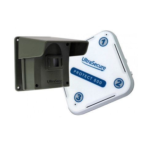
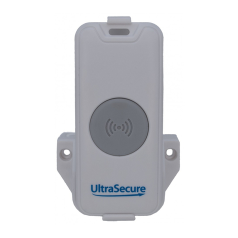
Ultra Secure UltraDial User manual

3G UltraDial GSM Alarm
Introduction
A Battery powered Weatherproof 3G GSM Wireless Alarm System with N/O & N/C Input
Trigger & Wireless Connectivity to a range of Wireless Accessories.
Key Points:
•Calls up to 3 x Key-holders by Telephone when Triggered (this can be turned off).
•Contacts up to 3 x Key-holders by SMS when Triggered (this can be turned off).
•User can Record a personal message (this will be replayed to Key-holders when the
Alarm Calls them.
•Armed & Disarmed using Remote Control (from up to 100 metres away).
•Battery Powered (can be operated using an optional Plug in Transformer).
•Volt Free N/O Input (can be used with wired N/O detectors & sensors).
•Volt Free N/C Input (can be used with wired N/C detectors & sensors).
•It can be connected to an existing Alarm Panel.
•Easy Programming (via built in keypad).
•Can operate with a Host of Wireless Detectors.
•Can trigger Wireless Sirens.
•Fully Waterproof (IP 66).
•Supplied with Security Screws and Tool (for the lid).
•It can send a Weekly Status report to the Primary Key-holder.
•Key-holder being Called can Disarm the Alarm.
•Key-holder being Called can Stop the Alarm and Re-arm.
•Uses standard size SIM Card (PAYG or Contract).
•Power Failure SMS (when used with a Plug in Transformer).
•Remote Arm & Disarm function (when used with a Plug in Transformer).

Get Started:
1. Remove the Lid by Removing 4 x Security Screws using the Tool supplied.
2. Insert the SIM Card (sim card holder located just below the Key-pad).
3. Connect any Wired Sensors or Alarm Panels to the N/O or N/C Input (further details
below).
4. Insert 3 x AA Batteries (lithium recommended for external use).
5. Program the Wireless Remote Controls to the Alarm (see operation below).
6. Program any Wireless Accessories to the Alarm (see operation below).
7. Program the Key-holders into the Alarm System (see operation below).
8. Set the Time & Day if the weekly status report is required (further information
below).
9. Carry out additional programming (full details below).
10. Fit the Alarm Unit into the desired location using 2 x Screws (not supplied due to
variations of possible Installations), this can be both Indoor & Outdoor.
Sim Card Installation:
** Please follow these steps closely as incorrect Sim Card installation can cause damage to
the Ultra PIR. **
(ACTUAL SIZE)

Insert the Largest (Standard) Sim Card into the SIM Card Holder (located under the built-in
keypad. Carefully slide and lift the top of the holder up as this is hinged, slide the SIM Card
into the top holder (you will see cut out corner of the lid showing you what direction it
should be inserted), Carefully close and slide the Lid onto the base unit.
This alarm does not support SIM card verification. Do not use PIN codes. If you are using a
brand new or existing SIM card please make sure the SIM card works in your mobile phone
and you can make calls and to send text messages, if it is unable to do so then you will not
receive any calls and/or texts.
The Alarm will notify you by 5 beeps (multiple times) if No working SIM Card is Inserted.
When you insert a working SIM Card, a small LED (located above the SIM Card holder) will
flash quickly for 1 to 2 minutes as the Network connection is established, this LED will go
out once established.
Input Relays:
There is 1 x Input Relays which can be used as a Volt Free Normally Open (N/O) or Normally
Closed (N/C) that can be used in conjunction with various devices.
Normally Open (going closed) would be connected as below:
Normally Closed (going open) would be connected as below:

Examples for using a N/O Input would be:
•Wired Water Alarms.
•Existing Alarm Panels.
•Our Perimeter Solar Power Beam.
Examples for using a N/C Input would be:
•Wired Window Contact.
•Wired Gate Contact.
•Wired Roller Shutter Contact.
When using a Wired Inputs, you would guide the cable through the cable glands located at
the bottom of the Alarm and locate the two terminal blocks to the left-hand side of the
battery compartment (as shown in images above).
To use the connectors, carefully press down on the slot headed cap on the terminal and
guide a thin cable (you may find a tinned cable easier to locate) into the side access holes,
then release the slot headed spring loaded cap and carefully pull the cable to ensure it is
located correctly.
Batteries:
This Alarm uses 3 x AA Batteries which will be fitted inside the Battery Compartment, the
Negative side of the Battery is fitted against the springs.
We recommend Lithium AA Batteries for any External Installation, or in buildings that will
get cold during the winter months, this is because Lithium Batteries are designed to operate
in lower temperatures.
Standard good quality Alkaline Batteries can be used for Internal Use.

DC Input:
The UltraDial can be powered by an external 5v DC Input for applications with access, the
options include:
•A Plug in Transformer (3 or 2-pin).
•USB Cable.
•Other 5v DC Power Supplies.
Please see the image below displaying the correct location of the Input Terminals when
using a 5v power source.
When using a 5v DC Input supply, standard Lithium or Alkaline Batteries (not re-chargeable)
can also be Inserted (although they will not be charged by the unit) which would ensure the
Alarm operates throughout a Mains Power Failure.
Please power the Alarm for the following procedures (using battery or transformer).
Programming (pairing) the Remote Control:
1) Press and hold the learn button (located on the circuit board to the right-hand side
of the SIM Card Holder.
2) Press the learn button on the back of the remote (Under the battery compartment)
3) Wait until you hear 2 beeps.
4) The Remote Control will now be paired with the Alarm.
5) Repeat the process (including stage 1) to program further Remote Controls to the
Alarm.
Press and hold both
buttons at the same
time until you hear a
‘Beep’

The Remote Control (controls) can be deleted from the Alarm by holding the learn button
inside the Alarm whilst inserting the last battery, 3 beeps will be heard, this indicates the
Remote Control has been deleted successfully.
Additional Wireless Detectors:
The UltraDial GSM Alarm System can be used with additional Wireless Detectors, these
include:
•Standard (non-gsm) PIR’s.
•GSM UltraPIR Alarms.
•Door & Window Contacts.
When these detectors are paired into the same Wireless Network, when any are triggered
they will automatically trigger the UltraDial GSM Alarm (which will start to dial key-holders)
together with triggering the Sirens built into any other PIR;s
The operating range between the UltraDial and Wireless Detectors is 100 metres (line of
sight) although this can be much further when multiple units are used as each unit will relay
the signal to the nearest unit.
Additional Wireless Sirens:
The UltraDial GSM Alarm System can be used with additional Wireless Sirens, these include:
•Battery Powered Internal.
•Battery or Solar Powered Internal or External.
These Sirens would be activated by any of the Detectors working within the same Wireless
Network.
The operating range between the UltraDial and Wireless Sirens is 100 metres (line of sight)
although this can be much further when multiple units are used as each unit will relay the
signal to the nearest unit.
Programming (pairing) additional Wireless Detectors & Sirens:
Wireless accessories are programmed (paired) via the Remote Controls, when a Remote
Control is paired to the UltraDial and Wireless accessories, they will operate as one Wireless
Network. The programming (pairing method) is a similar procedure to that of the UltraDial
& Remote Control (as shown above). The principle is that ALL devices need to be paired with
ALL Remote Controls being used, examples shown below.

Recording a voice message
A short (6 second) message can be Recorded into the Alarm, this would be replayed to Key-
holders when the Alarm calls them.
1) Under disarm mode, activate keypad by pressing the learn button (located to the
right-hand side of the SIM Card).
2) Press #1# on the Keypad.
3) Start recording your message (for a maximum of 6 seconds), Speak closely into the
microphone located near the keypad.
4) The Alarm will automatically reset after 6 seconds.
Programming the phone numbers
You can program up to three Key-holders Telephone Numbers into this Alarm (mobile or
landline), when the Alarm is Triggered it will contact these Key-holders by Telephone and/or
SMS (depending on your chosen settings).
Under disarm mode, activate keypad by pressing the learn button (located to the righthand
side of the SIM Card), then:
1) Press *1 + Phone Number + * (for first number).
2) Press *2 + Phone Number + * (for second number).
3) Press *3 + Phone Number + * (for third number).
Please Note: It may be necessary to use the County Code with some SIM Cards.
Solar Siren
BT PIR
Internal Siren

Examples:
Let’s assume your number is 01234567890 and you want it to be the first number the Alarm
Calls:
1) Press * 1 01234567890 * or *1 0044 1234567890* (on some networks).
If you want this phone number to be the third number the Alarm Calls:
1) Press * 3 01234567890 * or *3 0044 1234567890* (on some networks).
Full Programming:
There are further optional programming functions that can be used, please see below:
All functions are preceded by pressing the Learn Button
Please Note: 2 Audible Beeps denotes functions being turned ON, 1 Audible Beep denotes
functions being turned OFF.
Operation:
•#1# (record message) as listed above.
•#2# (allows you to Arm & Disarm the Alarm using the Built in Keypad).
•#6# (this controls any audible beep from the Alarm upon activation).
•#8# (this can turn ON or OFF the Telephone Function, if this is OFF the Alarm would
be able to send SMS (Text) Messages Only.
•#9# (this can turn ON or OFF the SMS Function, if this is OFF the Alarm would be able
to Call Key-holders Only.
•#0# (weekly status report ON or OFF) see below:
•#369# (full reset). Please allow a few seconds to complete.

Weekly Report:
This optional feature allows the Alarm to be programmed to send you a weekly status
report, which would be sent to the primary key-holder at 9am each Monday.
To turn this function OFF & ON please press the ‘Learn Button’ followed by #0#
The Report would contain:
•Battery Status.
•GSM Status.
•Armed or Disarmed.
The Time & Date will need to be programmed on the Alarm to allow it to send this status
report at the correct time:
•#0 (start of the command).
•Time (4-digit) 8.50am would be 0850.
•Day *1 = Monday, *2 = Tuesday, *3 = Wednesday, *4 = Thursday, *5 = Friday, *6 =
Saturday, *0 = Sunday.
•# (end of command).
Example:
If the time is 08:50am on a Monday, you would use the following code:
#0 0850*1#
Arming the Alarm:
•Press the ON ( ) Button on the Remote Control (from up to 100 metres away).
•One beep will be sounded to indicate the Alarm is armed.
•The alarm will become active after 30 seconds to allow exiting of the vicinity.
Disarming the Alarm:
•Press the OFF ( ) button on the remote fob.
•One beep will be sounded to indicate the Alarm is Disarmed.
Receiving a telephone call
** PLEASE NOTE THAT IT MAY TAKE UP TO 1 MINUTE TO RECEIVE A CALL, DEPENDING ON
THE NETWORK **
Once the Alarm is triggered it will call up to three designated telephone numbers.

The UltraDial will call for an estimated time of 25-30 seconds (may differ for each network)
before moving onto the next number. Upon receiving the Call, you have the option to;
•Press # on the receiving telephone, which will disarm the alarm (and all other
Wireless accessories) and prevent it calling any of the other telephone numbers,
additional Sirens will also be silenced.
•Press * on the receiving telephone, which will prevent the alarm from calling any
other telephone number, but the Alarm will remain Armed, additional Sirens will also
be silenced.
Whilst using the Alarm with Battery, there is no option to Remotely Arm & Disarm the Alarm
(see further details about operation using a Transformer below).
Notes:
When 3 telephone numbers are entered, each number will receive 1 call & 1 SMS.
When 2 telephone numbers are entered, the first number will receive 2 calls and 1 SMS, the
second number will receive 1 call and 1 SMS.
When 1 telephone numbers are entered, it will receive 3 calls and 1 SMS.
Alarm Operation when using a optional DC Input:
Operating the Alarm whilst using a Plug in Transformer or USB Cable is identical to the
above instructions, however there are the following additions:
Remote Operation:
This allows the primary Key-holder to Remotely Arm & Disarm the Alarm by sending an SMS
to the SIM Card Number, the commands are:
D = Disarm.
A = Arm.
Power Failure:
In the event of a Mains Power Failure, the Alarm will contact the primary Key-holder by SMS
informing them in the event of a Power Cut and when the Power is reconnected (this
function will require the Alarm to also have batteries inserted.
Specification:
Wireless Frequency: 868 Mhz.
GSM Frequency:
Battery Life: Approximately 6 months (using Lithium Batteries).
Size: 163 x 82 x 40 mm.
Colour: Black.
IP Rating: IP66.

Table of contents
Other Ultra Secure Security System manuals