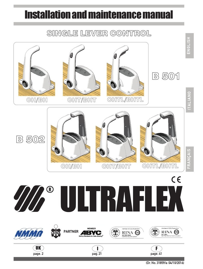
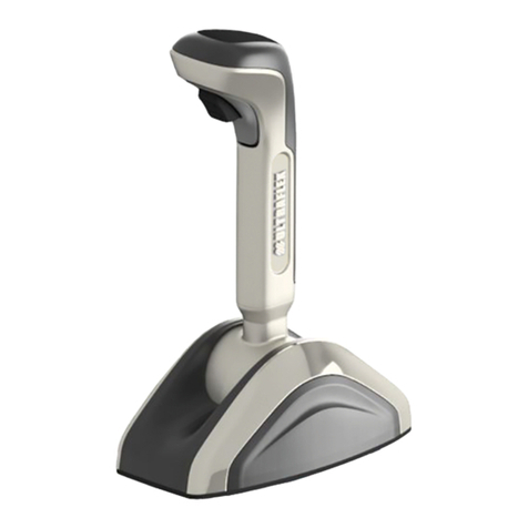
Ultraflex B 301 Manual

SINGLELEVERCONTROL
Installationandmaintenancemanual
PARTNER
R
B301
B302
ENGLISH
(Dr.No.23166/d01/10/2017)
I
UK F
page.2 pag. 17 page. 33
ITALIANO
FRANÇAIS

ULTRAFLEX S.p.A.
ULTRAFLEX
16015Casella(Genova) Italia-ViaCrose,2
ENGLISH
DearCustomer,
Wewould liketothankyouforchoosingan ULTRAFLEX product.
ULTRAFLEX hasbeenaleaderinsteeringsystemsforpleasureandprofessionalboatsformanyyears.
ULTRAFLEX productionissinceeversynonimousofreliabilityandsafety.
All ULTRAFLEX productsaredesignedandmanufacturedtoensurethebestperformance.
To ensureyoursafetyandtomaintainahighqualitylevel, ULTRAFLEX productsareguaranteedonly if
theyareusedwithoriginalspareparts.
ULTRAFLEX and UFLEX QualityManagementSystemsarecertifiedCISQ-IQNetby theItalianShipping
Registry(RINA),inconformitywiththeUNIENISO9001:2008 rule. ULTRAFLEX certificationNo.6669/02/S
(former420/96). UFLEX certificationNo.8875/03/S.
Thequalitymanagementsysteminvolvesallthecompanyresourcesandprocesses startingfromthe
design,inorderto:
- ensureproductqualitytothecustomer;
-maintainandimprove thequalitystandardsconstantly;
-pursueacontinuousprocess improvementtomeetthemarketneedsandtoincrease thecustomer
satisfaction
ULTRAFLEX EnvironmentalManagementSystemis certifiedCISQ-IQNetby theItalianShippingRegistry
(RINA),inconformitywiththeUNIENISO14001rule. ULTRAFLEX certificationNo.EMS-1282/S.
Productsforpleasureboatsareconstantlytestedtochecktheirconformitywiththe2013/53/EU.
"ULTRAFLEX has over80 yearsofexperience inthemarineindustryandis aworld leaderintheproduction
ofmechanical,hydraulicandelectronicsteeringsystems, controlboxes andsteeringwheelsforany
kindofpleasure, fishingorcommercialboats.
Thekey factorswhichexplaintheincreasingsuccess ofourproductsall overtheworld arethereliability
ofourproductsandthebeforeandaftersaleservice, thequalityofthecompanyorganizationandofthe
humanresourcesandthecontinuousspendinginresearchanddevelopment".

SINGLELEVERCONTROL B301 AND B302 -page 3 of 47
Installationandmaintenancemanual
ULTRAFLEX
ENGLISH
SECTION1-PRODUCTDESCRIPTION
1.1 PRODUCTDESCRIPTIONANDRECOMMENDATIONSFORUSE............................................................6
1.2 DIMENSIONS...................................................................................................................6
TABLEOFCONTENTS
SECTION2-TRANSPORT
2.1 GENERALWARNINGS.............................................................................................................................7
2.2 PACKAGE CONTENTS....................................................................................................................7
SECTION6-MAINTENANCE
6.1 ORDINARYMAINTENANCE.................................................................................................................15
6.2 SPECIALMAINTENANCE.....................................................................................................15
SECTION3-INSTALLATION
3.1 TOOLSREQUIRED........................................................................................................................8
3.2 CONTROL BOXINSTALLATION........................................................................................................8
3,3 ADJUSTMENT OFTHELEVER INCLINATION..........................................................................8
3,4 CONNECTINGCONTROLCABLE.............................................................................................9
3.5 INSTALLATIONOFCABLESC14AND MACH14.................................................................................9
3.5.1 SHIFTCABLECONNECTION............................................................................................................9
3,5,2 THROTTLE CABLECONNECTION.......................................................................................................11
3.6 ADJUSTINGTHECLUTCH.................................................................................................................12
3.7 LEVERCONTROL BOXMOUNTING........................................................................................12
3.8 INSTALLATIONOFTHENEUTRAL SAFETY SWITCH..................................................................13
SECTION5-SAFETYWARNINGS
5.1 SAFETYRULESDURINGINSTALLATIONANDUSE....................................................................14
5.2 CLOTHING..........................................................................................................................14
SECTION7-DISMANTLING
7.1 DISMANTLING.........................................................................................................................15
!
USEOFTHISMANUALANDSYMBOLS...............................................................................................................4
INTRODUCTION.................................................................................................................................5
WARRANTY................................................................................................................................5
SECTION4-LEVERUSE
4.1 LEVERUSE............................................................................................................................14
!
IMPORTANT:
Theadditionaldocuments"ApplicationGuide"and"SparePartsList" areattachedtothismanual.

Installationandmaintenancemanual
ULTRAFLEX
page 4 of 47-SINGLELEVERCONTROL B301 AND B302
ENGLISH
Inordertoprotecttheuser's safetyandguarantee correctfunctioningoftheproduct,this manualuses the
symbolsdescribedbelow.
USE OFTHISMANUALAND SYMBOLS
THEINSTALLATION AND MAINTENANCE MANUAL is thedocumentaccompanyingtheproductfromsaleto
replacementanddisposal,andshouldbeconsideredanintegralpartoftheproduct.
ReadthemanualbeforeundertakingANY ACTIVITY involvingtheproduct,includingmovementandunloading
fromthevehicleonwhichitisdelivered.
STERN
BOW
STARBOARD PORT
Thepictureasideexplainsthemeaningofsome
nauticalwordscontainedinthismanual.
DANGER ImmediatehazardswhichCAUSEseverepersonalinjuryordeath.
WARNING
CAUTION
Operationswhichshould beperformedbyqualifiedorspecialized
personneltoavoidrisksareidentifiedby thesymbolshownhere.
Providethepersonnelwhowill beinstallingtheproductwithappropriate
trainingandmakesurethattheyunderstandandimplementthe
instructionsprovided.
NOTICE Importantinformationforthecorrectinstallationandformaintenance,that
doesnotcauseanydamage.
Denotes thatahazard existswhichcanresult ininjuryordeathifproper
precautionsarenottaken.
Denotesareminderofsafetypracticesordirectsattentiontounsafe
practices whichcould result inpersonalinjuryordamagetothecraft or
componentsortotheenvironment.

SINGLELEVERCONTROL B301 AND B302 -page 5 of 47
Installationandmaintenancemanual
ULTRAFLEX
ENGLISH
WARRANTY
ULTRAFLEX warrantsthatitsproductsarebuilt accordingtothestandardsofgoodworkmanshipandarefree
ofdefectsinmaterialsandworkmanship.
This warrantyis validfortwoyearsstartingonthedateofmanufacturewiththeexceptionofcases inwhich
productsareinstalledandusedonworkingvesselsoronvesselscommercialuse,inwhichcase the
guaranteeis limitedto1yearfromthedateofmanufacture.
This warrantyis limitedtofreereplacementorrepairoftheitem,whichmustbereturnedcarriagepaid,
providedwefindittobeeffectively defectiveinmaterialsand/orworkmanship.
Thewarrantydoes notcoveranydirectorindirectdamages, Thewarrantyspecificallydoesnotcover,and
weshall notbeliablefor(exceptforreplacementorrepairofdefective itemsunderthetermsandconditions
setforthabove),malfunctioningofourproductsiftheirfailureorpoorfunctioningis attributabletoincorrect
installationortonegligentorimproperuse.
Thiswarrantydoes notcoverproductsinstalledonracingboatsorusedinacompetitivecontext.The
descriptionsandillustrationsinthis manualareindicativeonly.
Please contactourAssistance Service formoredetailedinformation.
Thecomponentsof ULTRAFLEX steeringandcontrolsystemswithEC markedcomponents. (See Art.3andArt.
5ofdirective 94/25/EC.)Notethatthe ULTRAFLEX warrantyshallbeautomaticallyforfeitedifany ULTRAFLEX
componentsareinstalledinasteeringandcontrolsystemalongwithproductsofotherbrands.
INTRODUCTION
This installationandmaintenancemanualconstitutesanintegralpartoftheproductandmustbemade
easilyaccessibleforpersonnelusingtheproductandperformingmaintenancework onit.
Theusermustknowthecontentofthis manual.
ULTRAFLEX shall notbeheld liableforanyinaccuraciesduetoprintingerrorsinthemanual.
Withoutalteringthebasic featuresoftheproductdescribed ULTRAFLEX reserves therighttomakeanychangesto
descriptions,detailsandillustrationsthatitmayconsiderappropriateforitsimprovementorformanufacturing
orcommercialreasonsatanytime, withoutbeingrequiredtoupdatethis publicationimmediately.
ALL RIGHTSRESERVED. Rightstopublication,trademarks, logosandphotographsof ULTRAFLEX productspresent
inthis manualarethepropertyof ULTRAFLEXandmay notbereproduced infullorinpart.Greatcarehas been
takentocollectandverifydocumentationtomakethis manualas completeandeasytounderstandaspossible.
Noneoftheinformationobtainedinthis publicationmay beinterpretedas aguarantee oranexpress orimplicit
condition-includingbutnotlimitedto, theguaranteeofsuitabilityforaparticularpurpose. Noneoftheinformation
containedinthis publicationmay beinterpretedas achangetoorassertionofthetermsofanycontractof
purchase.
Theproductmustbeinstalledbyexperiencedpersonneltoensurecorrectfunctioningoftheproductandits
components.Intheeventofbreakageofthecomponentsormalfunctioning,contactspecializedpersonnel
orourTechnicalAssistanceService.
WARNING
TECHNICALASSISTANCE SERVICE
UFLEX S.r.l.
ViaMiliteIgnoto,8A
16012Busalla(GE)-Italia
Tel:+39.010.962.01
Fax: +39.010.962.0333
Email: service@ultraflexgroup.it
www.ultraflexgroup.it
North-South-CentralAmerica:
UFLEX USA
6442ParklandDrive
Sarasota,FL34243
Tel:+1.941.351.2628
Fax: +1.941.360.9171
Email: sales@uflexusa.com
www.uflexusa.com

Installationandmaintenancemanual
ULTRAFLEX
page 6 of 47-SINGLELEVERCONTROL B301 AND B302
ENGLISH
1.2 Dimensions
1PRODUCTDESCRIPTION
1.1 Productdescriptionandrecommendations foruse
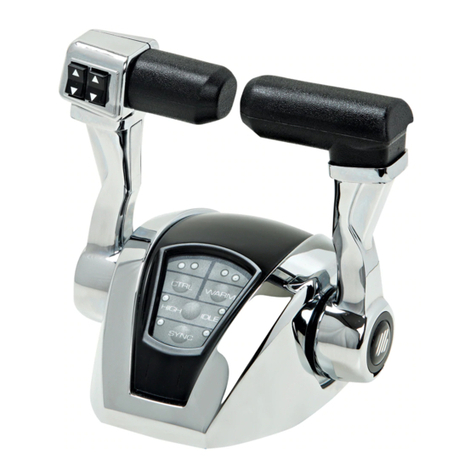
TheB301 singleengineandtheB302 dualenginecontrolsaredesignedas asingleleverdualfunctionper
engine. They arespecifically designedtooperatewithoutboard,sterndrive (I/O)andinbord marine
propulsionengines. ThecontrolscanoperatewithallUltraflex cables excepttheC4; K59kitis included
withboththecontrols,necessary toinstallUltraflex C2, C8,C0, andMach0cables.
Foralltheothercablesthefollowingkitsareavailableondemand:
-K60 forcables Ultraflex C5 -C16 -MACH5;
- K 61 forcables Ultraflex C22;
- K 62 forcables Ultraflex C36 -MACH36.
- Thecables C14 andMACH14 requirenoinstallationkit.
Fig1
Distanza minimaper
la corretta
installazionedeicavi
Thepictures belowshowthelevercontrolB301andB302dimensions.
B301 B302
Distanzaminimaper
lacorretta
installazionedeicavi
Minimumdistance
toallowthe
cableinstallation
Minimumdistance
toallowthe
cableinstallation

SINGLELEVERCONTROL B301 AND B302 -page 7 of 47
Installationandmaintenancemanual
ULTRAFLEX
ENGLISH
Disposeofpackaginginaccordance withthelaw.
2.1 Generalwarnings
2TRANSPORTATION
Theproductanditspackagingweighabout2.5kg (5.5pounds)andcanthereforebemovedbyhand.
2.2 Package contents
Beforeusingthedevice,checkthatithas notsuffereddamageduringtransportationorstorage.Also
checkthatall thecomponentssuppliedwithitarecontainedinthepackage(refertolist).Ifyou
identifyanydamage, notifythecarrierandyoursupplier.
WARNING
Personnelhandlingtheloadmustworkwithsafetyglovesandfootwear.
WARNING
Contentsofthelever controlpackaging:
A
B
F
B301
B302
A
D
C
EG
I
H
REF B301 B302
A
1levercontrol 1lever control
B
4screwsM5x35 4screwsM5x35
C
4nutsM5 4nutsM5
D
4washers 4washers
E
3snaprings 6snaprings
F
1kitK59for cableinstallation 2kitsK59forcableinstallation
G
1screwM5x12 2 screwsM5x12
H
1plate 2plates
I
1pin 2pins

Installationandmaintenancemanual
ULTRAFLEX
page 8 of 47-SINGLELEVERCONTROL B301 AND B302
ENGLISH
3INSTALLATION
3.1Toolsrequired
Phillips
screwdriver
Pliers Openend
wrench
8mm [0,31”]
Socket wrench
17mm [0,66”]
1Remove therubber
coverfromthelever
hub(1).
3.3Adjustmentoftheleverinclination
Theleverangularpositioncanbeadjustedbothforward andbackward accordingtothecontrolposition.
Followtheinstructionsbelow:
1
2Extracttheplastic
pin(2).
4Extractthelever
andturnittothe
desiredposition,then
reinsertitbyputting
intogearwiththe
shaftofthecontrol
box.
2
3Takeoutthe
hexagonalheadscrew
(3)witha17socket
wrench.
3
3.2Controlboxinstallation
1Install thecontrolinapositionthatallowsthelevertorotatefree andtakecarethatitcanreachthe
fullforwardandfullreversestroke.
2Refertotheoverall dimensionsgiveninparagraph1.2 tocheckthatthebox caneffectively be
installedinthedesiredposition.
3Afterdeterminingtheappropriatelocation,drill theholes requiredtoassemblethecontrolbox
usingthetemplateprovidedforsingleordualcontrol.
Whenthecableisinstalledavoidtoonarrowbends.
WARNING
NOTICE
Forthesingleanddualcontrolinstallationrefertothedrillingtemplatesenclosed.
Connectthecablestotheleverbeforethelevercontroltothedashboard.
CAUTION
Theuse ofaproperkillingswitchsystemis recommendedforeachULTRAFLEXcontrolsysteminstallation.

SINGLELEVERCONTROL B301 AND B302 -page 9 of 47
Installationandmaintenancemanual
ULTRAFLEX
ENGLISH
3.4Connectingcontrolcable
1Selectadirectpathwithaminimumnumberofbendsandwithoutanyobstacles.
Avoidtoonarrowbends(theminimum bendradiusis 203 mm(8")).
WARNING
NOTICE
Outboard engineinstallationsrequireanadditionallengthofabout120cm(47")ofthecables toallow
engineswing.
Thecablescanbefixedwithsuitablecable hangers(suppliedseparately)orroutedthroughsegmentsof
conduit(suppliedseparatelytoo)forlongstraightruns.
WARNING
2CONTROLB301:
Removetherear
cover (4) ofthecontrol
by(unscrewing)the
screws (5) soas to
reacheasilythe
elementswherethe
cables aretobefixed.
45
5
CONTROL B302:
Spilt thetwoboxes
(6),byremoving
thescrews (5).
5
5
6 6
3Aspecificfittingkitisavailableforeachcabletype,K59kitisalso includedwithbothsinglelevers
B301 andB302.
Toinstallthecablesonthecontrol/controlsfollowtheinstructionsprovidedwitheachkit.
To installthecables C14 andMACH14 followtheinstructionsgivenbelow.
B301 B302
5Applythreadlocking lowstrength (Loctite222)onthescrew(3)andfastenitcompletely.
Insertthepinonthescrew(2).Inserttherubbercover(1).
Makesurethechosenangularpositionallowsthecorrectstrokeofthecable.
WARNING
3.5InstallationofcablesC14andMach14
3.5.1 Shift cableconnection
1Positionthe
controlbox onaplane
surfaceasinthe
picture(theUltraflex
logoonthelevermust
bevisible).
Removethecable
fastener(7)fromthe
plate(8)throughthe
screws(9).
2Mountthecable
makingsurethe
cablecylinder(10)is
placedinsidethe
platehole(11).
7
8
910
11
Toavoidthecontrolstiffening,donotfixthecablesnearthecontroloutlet(theminimumfixing
distance is500mm)andinanycase donotuse fixingsystemsthatcandeformthecableconduit.

Installationandmaintenancemanual
ULTRAFLEX
page 10 of 47-SINGLELEVERCONTROL B301 AND B302
ENGLISH
3Remountthe
cablefastener(7)on
theplate(8)aligning
thecylinderofthe
connector(10)withthe
holeofthecable
fastener.
4Fixthecable
fastener(7)totheplate
(8)withthescrews(9).
7
8
10
9
8
6Turnthecontrol
boxupsidedown
(internalmechanism
lookingupward).
Putthepin(I)inoneof
thethree holes (a),(b),
or(c)ofthelever(12).
NOTICE
Theholeischosenaccordingtothestrokeofthecable(seethetablebelow).
7
I
12
5Measuretheengineshiftleverstrokefromthe
forwardgeartothereversegear.Seethepossible
strokes onthecontroldevice andselectthenearestone;
forinstance,ifthestrokeontheengine(fromoneend
ofstroketotheother)is67 mm,thecablemustbe
connectedtothemoreinternalhole(68 mm stroke).If a
strokeof70 mm is detected,checkifthe68 mm stroke
is sufficientotherwiseconnectthecabletothecentral
hole(76 mm stroke);somemillimeters(5-6)ofsurplus
strokeonthecontroldevicearecounterbalancedby
thecableplay.
b
HOLE a b c
STROKE [mm ]
68 76 82
a
b
c
c
a
Adjusttheshift cablestrokeinordertonotforce thetopandthebottomoftheenginestroke.
Thenon-compliance withthisrecommendationcausesthecontrolsystemmalfunctionsuchas:
-Highresistancetotheleveroperation
-Earlywearofthemechanismthatcancause itslocking.
WARNING

SINGLELEVERCONTROL B301 AND B302 -page 11 of 47
Installationandmaintenancemanual
ULTRAFLEX
ENGLISH
7Engagetherod
(13)onthepin(I)
8Mounttheplate
(H)inthewayshown
inthepictureandfix
itwiththescrew(G)
onthehole(14).
Checktherightsettingofshift cablestrokeandmakesurethatiscompliantwiththefollowingconditions.
WARNING
Duringtheshift engagement,thelevermovementmustbealwaysfluidwithaconstantresistance.
Thelevermustnobecomestifferduringthethrottleengagement,otherwisecheckthatthecontrolshift
strokecorrespondstotheengineone.
13
I
GH
14
3.5.2 Throttlecableconnection
1Removethecablefastener(7)fromtheplate
(8)removingthescrews(9).
3Engagetherod(16)onthepin(17).
7
8
9
4Remountthecable
fastener(7)ontheplate
(8)aligningthecable
cylinder(10)withthe
holeofthecable
fastener.
Fixthecablefastener
totheplatewiththe
screws(9).
2Mountthecablemakingsurethecable
cylinder(10)is placedinsidetheplatehole(15).
15
10
10
7
8
9
16
17
5Fix thecable insertingthecirclip(E)inthe
groove ofthepin(17).
E
17
NOTICE
17A
15A
Forpushaction
throttle, connectthe
cable rodonthepin
(17A)andinsertthe
cablecylinderinto
theplatehole(15A).

Installationandmaintenancemanual
ULTRAFLEX
page 12 of 47-SINGLELEVERCONTROL B301 AND B302
ENGLISH
Boththecontrolboxes B301 andB302 allowtheadjustmentoftheclutch.Followtheinstructionsbelow:
3.6Adjustingtheclutch
3.7Levercontrolboxmounting
1Rotatetheleverinthemiddlethrottleposition;
2
2Screwthedowel(18)toobtainthehardeningoftheclutch,or
unscrewittoobtainasmoothermovement.Tocheckthefrictionof
thelever,move itclockwise andcounterclockwise. ADJUSTING THE
CLUTCHMUSTBE PERFORMED WITHENGINE TURNED OFF AND THE
LEVER INTHROTTLE POSITION.
3CONTROLB301:
Placetherearcover
(4)fixingitwiththe
screws(5).
45
5
CONTROL B302:
Connectthetwo
boxes(6)withthe
screws(5).
5
5
6 6
B301 B302
1Putthecontrolbox
intheselected
position,theninsert
andthightenthefour
screwsM5x35(B),
withwashers(D)and
nuts(C).
B
D
C
B
D
C
B301 B302
18
WARNING
DOING THISSETTING INGEAR POSITION CAN DAMAGE THESYSTEM.
2Place thestickersuppliedonthechromium platedcovering.

SINGLELEVERCONTROL B301 AND B302 -page 13 of 47
Installationandmaintenancemanual
ULTRAFLEX
ENGLISH
3.8Installationoftheneutralsafetyswitch
1Put thelever
forwarduntilthe
holes ontheplate(20)
canbeseenthrough
theslotontheplate
(19).
Thisoptionaldevice allowsstartingtheengineonlywiththeshift inneutralposition,avoidingunexepected
movementsoftheboat.
To assembleitdo as follows:
2Positionthe
device(23)on
plate(22)inserting
thecylinder(24)
insidetheplastic
guide(25).
19
20
23
24
22
25
21
Ifyouare installingthe switchX12, the screw andthenutmustbe inserted insidethehole(A).Forthe
switchX41, the reference hole is (B).
3Throughtheslotlocatedon
theplate(21),insertthescrew(26)
intheswitchholethroughthehole
oftheplate(22).
Insertthenut(27)fromtheouter
sideoftheplate(22)andtighten
thescrew(26).
NOTICE
21
22
26
27
A
B

Installationandmaintenancemanual
ULTRAFLEX
page 14 of 47-SINGLELEVERCONTROL B301 AND B302
ENGLISH
ATTENZIONE
SHIFTENABLING
THROTTLE
ENABLING
Theleverstrokeis madeupoftwomovements:
operatingtheshift inthefirst30°andthethrottlein
therestofthestroke.
Theboatmoves forward whentheleveris inforward
position,anditmoves backward whentheleveris put
inreverseposition.Tounlockthethrottlewithout
engagingagearpress thebuttonlocatedonthelower
partoftheleverandatthesametimeputthelever
forward.
DANGER
Beforestartingtheengine,ifthecontrolisnotprovidedwithsafetyswitch,makesurethattheleverisin
neutralposition.
4USE
4.1 Leveruse
ATTENZIONE
5SAFETYWARNINGS
This sectionillustratesthesafetyregulationstobeappliedforproperuseoftheapparatus.
Readthis sectionvery carefully andalso readthemanualssuppliedwithothercomponentsofthesingle
levercontrol.
5.1 Safety warningsduringinstallationanduse
OBLIGATORYFOLLOWtheprecautionsandsafetycriteriaindicatedbelow.
ULTRAFLEX shall notbeheld liablefortheuser's failuretoobservetheseprecautionsandcriteriaandshall
notbeheldliableforanynegligenceinuse ofthesystem.
-NEVERPUTHANDSBETWEENTHEMOVINGPARTS.
-Do notdeactivatesafetydevicesorrendertheminoperative.
-Donotmodifythesystemoradddevicestoitwithoutwrittenauthorizationortheinterventionofan
ULTRAFLEX techniciandescribingthechangemadeinthedescriptionoftheworkperformed.
-Do notuse theapparatusforanypurpose otherthanitsintendedpurpose as specifiedintheinstallation
andmaintenancemanual.
-Donotallowuntrainedpersonneltoperforminstallation.
DANGER
WARNING
-Duringinstallationofthesystem,takeparticularcare tokeepeverythingcleantoensurethatno
foreignbodiescangetintothesystem.Evenatinyobjectcancausepermanentdamagewhichmay
notbeimmediately obvious.
-Avoidcablecurve radiuses of<200 mm (8").
-Donotletcables comeintocontactwithsharp cornersoredges.
-Donotletcables comeintocontactwithheatsources.
DONOT wearnecklaces,braceletsoranyloosegarmentsthatcouldgetcaughtinmovingpartsduring
installation,inspectionormaintenancework.
5.2Clothing
WARNING
!

SINGLELEVERCONTROL B301 AND B302 -page 15 of 47
Installationandmaintenancemanual
ULTRAFLEX
ENGLISH
6.1Ordinary maintenance
6MAINTENANCE
Failuretoapplymaintenance controlsmay result inloss ofcontrolwhendriving,whichcanresult indamage
topropertyand/orinjury.
Maintenance requirementswill varydependingonclimateandfrequency andtypeofuse. Inspectionsmust
beconductedatleasteverytwoyearsby anexperienced nautical mechanic.
Performthefollowingmaintenanceoperations:
-Periodicallywashcomponentswithfreshwaterandremoveanysaltdeposits
-Onceamonth,checkall nutsholdingthesysteminplaceandtightenifnecessary.
WARNING
DANGER
Looseningorseparationofnutsholdingthesysteminplace cancause notonly malfunctioning
ofthesinglelevercontrolbutdamageorinjury.
-Periodicallychecktheabsence ofcorrosiononthemetalpartsofthecableterminalsandofabrasionson
thesheath.
-Replacedamagedpartsthatmaycompromisetheintegrityofthesinglelevercontrol.
Technical Assistance
Foranyinformationorassistancewithparticularapplicationspleasecontactourtechnical assistance
service(See paragraph"Introduction").
6.2Specialmaintenance
7DISMANTLING
7.1Dismantling
If youintendnottouse thesinglelevercontrolsystemanymore, dispose ofitinanenvironmentallysound
way.
Sheaths,hosesandcomponentsmadeofplasticorothernon-metallicmaterialsmustbedismantledand
disposedofseparately.

Installationandmaintenancemanual
ULTRAFLEX
page 16 of 47-SINGLELEVERCONTROL B301 AND B302
ENGLISH
NOTES

COMANDOMONOLEVA
Manualediinstallazioneemanutenzione
SOCIO
R
B301
B302
ITALIANO

GentileCliente,
Laringraziamoperaversceltoun prodotto ULTRAFLEX.
ULTRAFLEX èdaanniun puntodiriferimentoneisistemidiguidanelsettoredellanauticadadiportoe
professionale.
Dasemprelaproduzione ULTRAFLEX èsinonimodigrandeaffidabilitàesicurezza.
Tuttiiprodotti ULTRAFLEX sonoprogettatieprodottipergarantiresempreleprestazionimigliori,rela-
tivamentealloscopo percuisonoconcepiti.
PertutelarelaVostrasicurezzaepermanteneresempreunaltolivelloqualitativo ULTRAFLEX garanti-
sceipropriprodottisoloseutilizzaticoniricambioriginali.
ISistemidiGestioneQualità ULTRAFLEX ed UFLEX sonocertificatiCISQ-IQNetdalRINARegistroItaliano
Navale, inconformitàallaNormaUNIENISO9001:2008.Certificato ULTRAFLEX n°6669/02/S(già420/96).
Certificato UFLEX n°8875/03/S.
IlsistemaQualitàcoinvolgetuttelerisorseediprocessi aziendaliapartiredallaprogettazione,per:
- garantirealclientelaqualitàdelprodotto;
- impostareleazionipermantenereemigliorareneltempoglistandard diqualità;
-perseguireun continuomiglioramentodell'efficacia edell'efficienza dei processi perpoteressere
sempreinsintoniaconleesigenze delmercatoedaccrescerelasoddisfazionedei Clienti.
Il sistemadiGestioneAmbientaleUltraflex ècertificatodaCISQ-IQNetdalRINA RegistroItalianoNavale,
inconformitàallaNormaUNIENISO14001.Certificato ULTRAFLEX n°EMS-1282/S.
Iprodottidestinatiallanautica dadiportovengonocostantementecontrollatiperverificarelarispondenza
airequisitiimpostidalladirettiva2013/53/UE.
ULTRAFLEX S.p.A.
ULTRAFLEX
16015Casella(Genova) Italia-ViaCrose,2
"ULTRAFLEX,conpiùdi80annidiesperienza nelsettorenauticoèoggileaderglobalenellaproduzione
disistemidiguidameccanici, idrauliciedelettronici, scatoledicomandoevolantiperimbarcazionia
motoredadiporto, dapesca odalavorodiognidimensioneetipodimotorizzazione.
L'affidabilitàdei nostriprodottiedilservizio anteepostvendita, laqualitàdell'organizzazioneaziendalee
dellerisorse umaneinsiemeagliinvestimenticontinuiinricerca esvilupposonofattorideterminantiper
spiegareilsuccesso crescente dei nostri prodottiovunque nelmondo".
ITALIANO

COMANDOMONOLEVAB301 EB302 -pag.19 di47
Manualediinstallazioneemanutenzione
ULTRAFLEX
ITALIANO
SEZIONE1-DESCRIZIONEDELPRODOTTO
1.1 DESCRIZIONEDELPRODOTTOERACCOMANDAZIONISULL'UTILIZZO.................................................22
1.2 DIMENSIONI.................................................................................................................22
INDICEGENERALE
SEZIONE2-TRASPORTO
2.1 AVVERTENZEGENERALI.............................................................................................................................23
2.2 CONTENUTO IMBALLO...........................................................................................................................23
SEZIONE6-MANUTENZIONE
6.1 MANUTENZIONEORDINARIA.................................................................................................................31
6.2 MANUTENZIONESTRAORDINARIA.....................................................................................................31
SEZIONE3-INSTALLAZIONE
3.1 UTENSILINECESSARI.................................................................................................................................24
3.2 POSIZIONAMENTODELLASCATOLADICOMANDO.......................................................................24
3,3 REGOLAZIONEDELL'INCLINAZIONEDELLA LEVA.................................................................24
3,4 POSIZIONAMENTODEICAVIDICONTROLLO.........................................................................25
3.5 INSTALLAZIONECAVIC14EMACH14.................................................................................25
3.5.1COLLEGAMENTODEL CAVO PERILCONTROLLO DELL'INVERTITORE......................................25
3,5,2COLLEGAMENTODELCAVO PER ILCONTROLLO DEL GAS......................................................27
3.6 REGOLAZIONEDEL DISPOSITIVO DIFRIZIONAMENTO..............................................................................28
3.7 FISSAGGIODELLASCATOLADICOMANDOALLAPLANCIA....................................................28
3.8 INSTALLAZIONEDEL NEUTRALSAFETYSWITCH..................................................................29
SEZIONE5-AVVERTENZEDISICUREZZA
5.1 NORMEDISICUREZZADURANTEL'INSTALLAZIONEEL'USO............................................................30
5.2 ABBIGLIAMENTO.....................................................................................................................................30
SEZIONE7-SMANTELLAMENTO
7.1 SMANTELLAMENTO.........................................................................................................................31
!
USODEL MANUALEESIMBOLOGIAIMPIEGATA............................................................................................20
LETTERAINFORMATIVA....................................................................................................................................21
GARANZIA................................................................................................................................21
SEZIONE4-USO DELLALEVA
4.1 USODELLALEVA...................................................................................................................30
!
IMPORTANTE:
Inallegatoalpresentemanualevienefornitaladocumentazioneaggiuntivadenominata"ApplicationGuide"e
"SparePartsList".

Manualediinstallazioneemanutenzione
ULTRAFLEX
pag.20 di47-COMANDOMONOLEVAB301 EB302
ITALIANO
USODELMANUALEESIMBOLOGIA IMPIEGATA
Il MANUALE DIINSTALLAZIONEEMANUTENZIONEèildocumentocheaccompagnailprodottodalmomento
dellasuavenditafinoallasuasostituzioneesmaltimento.Risultacioè essereparteintegrantedellostesso.
E’ richiestalaletturadelmanualeprimachevengaintrapresaQUALSIASI ATTIVITA' checoinvolgailprodottocompre-
sa lamovimentazioneeloscarico dellostesso dalmezzo ditrasporto.
POPPA
(STERN)
PRUA
(BOW)
TRIBORDO
DRITTA
(STARBOARD)
BABORDO
SINISTRA
(PORT)
La figuraalatohalafunzionedifacilitarel'inter-
pretazionedialcunitermininauticicontenutinel
presentemanuale.
PERICOLO DanniimmediaticheCAUSANOferitegraviallapersonaocheportano
allamorte.
AVVERTENZA
ATTENZIONE
Le operazioniperlacuiesecuzionesi richiede, ondeevitarepossibili
rischi, personalequalificatoospecializzatosonoevidenziateconil
simboloindicatoalato.
Siraccomandadiformareilpersonaledestinatoall’installazionedel
prodottoediverificarechequantoprevistosia compreso edattuato.
NOTA Informazioneritenutaimportanteperunainstallazioneadeguataeperla
manutenzione, chenonècausa didanni.
Indicacheesisteun pericolochepuòcausarelesioneomortesenon
sonoadottateleprecauzioniappropriate.
Indica un richiamoall'applicazionedipratichedisicurezza oppurerichiama
l'attenzionesupratichenonsicurechepotrebberocausarelesione
personaleodannoall'imbarcazioneoaicomponentioall'ambiente.
This manual suits for next models
1
Table of contents
Languages:
Other Ultraflex Controllers manuals