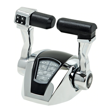
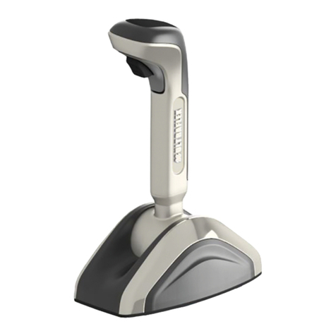
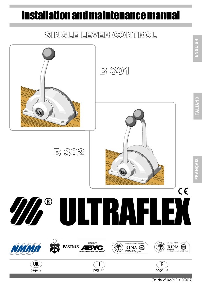
Ultraflex B 502 Manual

SINGLE LEVER CONTROL
Installationandmaintenancemanual
ULTRAFLEX
PARTNER
R
E N G L I SH
(Dr. No. 31859/a 04/10/2016)
I
UK F
page. 2 pag. 21 page. 41
IT A L IA N O
F R A N Ç A I S
B 501
B 502
CH/BH CHT/BHT CHTL/BHTL

ULTRAFLEX S.p.A.
ULTRAFLEX
16015 Casella (Genova) Italia - Via Crose, 2
E N G L I SH
Dear Customer,
We would like to thank you for choosing an ULTRAFLEX product.
ULTRAFLEX has been a leader in steering systems for pleasure and professional boats for many years.
ULTRAFLEX production is since ever synonimous of reliability and safety.
All ULTRAFLEX products are designed and manufactured to ensure the best performance.
To ensure your safety and to maintain a high quality level, ULTRAFLEX products are guaranteed only if
they are used with original spare parts.
ULTRAFLEX and UFLEX Quality Management Systems are certified CISQ-IQNet by the Italian Shipping
Registry (RINA), in conformity with the UNI EN ISO 9001:2008 rule. ULTRAFLEX certification No. 6669/02/S
(former 420/96). UFLEX certification No. 8875/03/S.
The quality management system involves all the company resources and processes starting from the
design, in order to:
- ensure product quality to the customer;
- maintain and improve the quality standards constantly;
- pursue a continuous process improvement to meet the market needs and to increase the customer
satisfaction
ULTRAFLEX Environmental Management System is certified CISQ-IQNet by the Italian Shipping Registry
(RINA), in conformity with the UNI EN ISO 14001 rule. ULTRAFLEX certification No. EMS-1282/S.
Products for pleasure boats are constantly tested to check their conformity with the 2013/53/EU.
"ULTRAFLEX has over 80 years of experience in the marine industry and is a world leader in the production
of mechanical, hydraulic and electronic steering systems, control boxes and steering wheels for any
kind of pleasure, fishing or commercial boats.
The key factors which explain the increasing success of our products all over the world are the reliability
of our products and the before and after sale service, the quality of the company organization and of the
human resources and the continuous spending in research and development".

SINGLE LEVER CONTROL B501 AND B502 - page 3 of63
Installation and maintenance manual
ULTRAFLEX
E N G L I SH
SECTION 1 - PRODUCT DESCRIPTION
1.1 PRODUCT DESCRIPTION AND RECOMMENDATIONS FOR USE...........................................................6
1.2 DIMENSIONS..................................................................................................................6
TABLE OF CONTENTS
SECTION 2 - TRANSPORT
2.1 GENERAL WARNINGS............................................................................................................................7
2.2 PACKAGE CONTENTS....................................................................................................................7
SECTION 6 - MAINTENANCE
6.1 ORDINARY MAINTENANCE.................................................................................................................17
6.2 SPECIAL MAINTENANCE....................................................................................................17
SECTION 3 - INSTALLATION
3.1 TOOLS REQUIRED.......................................................................................................................8
3.2 CONTROL BOX INSTALLATION........................................................................................................8
3,3 ADJUSTMENT OF THE LEVER INCLINATION (EXCEPT CHTL/BHTL VERSION NOT INCLUDED)..........8
3,4 CONNECTING CONTROL CABLE .............................................................................................9
3.5 INSTALLATION OF CABLES C14 AND MACH 14.................................................................................9
3.5.1 SHIFT CABLE CONNECTION............................................................................................................9
3,5,2 THROTTLE CABLE CONNECTION.......................................................................................................11
3.6 ADJUSTING THE CLUTCH.................................................................................................................12
3.7 LEVER CONTROL BOX MOUNTING........................................................................................12
3.8 INSTALLATION OF THE NEUTRAL SAFETY SWITCH..................................................................13
3.9 TRIM ELECTRICAL CONNECTIONS.............................................................................................................14
SECTION 5 - SAFETY WARNINGS
5.1 SAFETY RULES DURING INSTALLATION AND USE...................................................................16
5.2 CLOTHING.........................................................................................................................16
SECTION 7 - DISMANTLING
7.1 DISMANTLING.........................................................................................................................17
!
USE OF THIS MANUAL AND SYMBOLS ............................................................................................................4
INTRODUCTION.................................................................................................................................5
WARRANTY................................................................................................................................5
SECTION 4 - LEVER USE
4.1 LEVER USE...........................................................................................................................15
4.2 TRIM OPERATION....................................................................................................................15
!
IMPORTANT:
The additional documents "Application Guide" and "Spare Parts List" are attached to this manual.

Installation andmaintenance manual
ULTRAFLEX
page 4 of 63 - SINGLE LEVER CONTROL B501 AND B502
E N G L I SH
In order to protect the user's safety and guarantee correct functioning of the product, this manual uses the
symbols described below.
USE OF THIS MANUAL AND SYMBOLS
THE INSTALLATION AND MAINTENANCE MANUAL is the document accompanying the product from sale to
replacement and disposal, and should be considered an integral part of the product.
Read the manual before undertaking ANY ACTIVITY involving the product, including movement and unloading
from the vehicle on which it is delivered.
STERN
BOW
STARBOARD PORT
The picture aside explains the meaning of some
nautical words contained in this manual.
DANGER Immediate hazards which CAUSE severe personal injury or death.
WARNING
CAUTION
Operations which should be performed by qualified or specialized
personnel to avoid risks are identified by the symbol shown here.
Provide the personnel who will be installing the product with appropriate
training and make sure that they understand and implement the
instructions provided.
NOTICE Important information for the correct installation and for maintenance, that
does not cause any damage.
Denotes that a hazard exists which can result in injury or death if proper
precautions are not taken.
Denotes a reminder of safety practices or directs attention to unsafe
practices which could result in personal injury or damage to the craft or
components or to the environment.

SINGLE LEVER CONTROL B501 AND B502 - page 5 of63
Installation and maintenance manual
ULTRAFLEX
E N G L I SH
WARRANTY
ULTRAFLEX warrants that its products are built according to the standards of good workmanship and are free
of defects in materials and workmanship.
This warranty is valid for two years starting on the date of manufacture with the exception of cases in which
products are installed and used on working vessels or on vessels commercial use, in which case the
guarantee is limited to 1 year from the date of manufacture.
This warranty is limited to free replacement or repair of the item, which must be returned carriage paid,
provided we find it to be effectively defective in materials and/or workmanship.
The warranty does not cover any direct or indirect damages, The warranty specifically does not cover, and
we shall not be liable for (except for replacement or repair of defective items under the terms and conditions
set forth above), malfunctioning of our products if their failure or poor functioning is attributable to incorrect
installation or to negligent or improper use.
This warranty does not cover products installed on racing boats or used in a competitive context. The
descriptions and illustrations in this manual are indicative only.
Please contact our Assistance Service for more detailed information.
The components of ULTRAFLEX steering and control systems with EC marked components. (See Art. 3 and Art.
5 of directive 94/25/EC.) Note that the ULTRAFLEX warranty shall be automatically forfeited if any ULTRAFLEX
components are installed in a steering and control system along with products of other brands.
TECHNICAL ASSISTANCE SERVICE
INTRODUCTION
UFLEX S.r.l.
Via Milite Ignoto,8A
16012 Busalla (GE)-Italy
Tel: +39.010.962.0239 (Italy)
Tel: +39.010.962.0244 (international)
Fax: +39.010.962.0333
Email: ut@ultraflexgroup.it
www.ultraflexgroup.it
North - South - Central America:
UFLEX USA
6442 Parkland Drive
Sarasota, FL 34243
Tel: +1.941.351.2628
Fax: +1.941.360.9171
Email: uflex@uflexusa.com
www.uflexusa.com
This installation and maintenance manual constitutes an integral part of the product and must be made
easily accessible for personnel using the product and performing maintenance work on it.
The user must know the content of this manual.
ULTRAFLEX shall not be held liable for any inaccuracies due to printing errors in the manual.
Without altering the basic features of the product described ULTRAFLEX reserves the right to make any changes to
descriptions, details and illustrations that it may consider appropriate for its improvement or for manufacturing
or commercial reasons at any time, without being required to update this publication immediately.
ALL RIGHTS RESERVED. Rights to publication, trademarks, logos and photographs of ULTRAFLEX products present
in this manual are the property of ULTRAFLEXand may not be reproduced in full or in part. Great care has been
taken to collect and verify documentation to make this manual as complete and easy to understand as possible.
None of the information obtained in this publication may be interpreted as a guarantee or an express or implicit
condition- including but not limited to, the guarantee of suitability for a particular purpose. None of the information
contained in this publication may be interpreted as a change to or assertion of the terms of any contract of
purchase.
The product must be installed by experienced personnel to ensure correct functioning of the product and its
components. In the event of breakage of the components or malfunctioning, contact specialized personnel
or our Technical Assistance Service.
WARNING

Installation andmaintenance manual
ULTRAFLEX
page 6 of 63 - SINGLE LEVER CONTROL B501 AND B502
E N G L I SH
1.2 Dimensions
1 PRODUCT DESCRIPTION
1.1 Product description and recommendations for use
The B501 single engine and the B502 dual engine controls are designed as a single lever dual function per
engine. They are specifically designed to operate with outboard, stern drive (I/O) and inbord marine
propulsion engines. The controls can operate with all Ultraflex cables except the C4; K59 kit is included
with both the controls, necessary to install Ultraflex C2, C8, C0, and Mach 0 cables.
For all the other cables the following kits are available on demand:
- K 60 for cables Ultraflex C5 - C16 - MACH 5;
- K 61 for cables Ultraflex C22;
- K 62 for cables Ultraflex C36 - MACH 36.
- The cables C14 and MACH14 require no installation kit.
The pictures below show the lever control B501 and B502 dimensions.
B501 B502
Minimum distance
to allow the
cable installation
Minimum distance
to allow the
cable installation

SINGLE LEVER CONTROL B501 AND B502 - page 7 of63
Installation and maintenance manual
ULTRAFLEX
E N G L I SH
Dispose of packaging in accordance with the law.
2.1 General warnings
2 TRANSPORTATION
The product and its packaging weigh about 3.4 kg (7.5 pounds) and can therefore be moved by hand.
2.2 Package contents
Before using the device, check that it has not suffered damage during transportation or storage. Also
check that all the components supplied with it are contained in the package (refer to list). If you
identify any damage, notify the carrier and your supplier.
WARNING
Personnel handling the load must work with safety gloves and footwear.
WARNING
Contents of the control system packaging:
A
B
F
B501
B502
A
D
C
EG
I
H
REF B501 B502
A
1 lever control
1 lever control
B
4 screws M5x30
4 screws M5x30
C
4 nuts M5
4 nuts M5
D
4 washers
4 washers
E
3 snap rings
6 snap rings
F
1 kit K59 for cable installation
2 kits K59 for cable installation
G
1 screw M5x12
2 screws M5x12
H
1 plate
2 plates
I
1 pin
2 pins

Installation andmaintenance manual
ULTRAFLEX
page 8 of 63 - SINGLE LEVER CONTROL B501 AND B502
E N G L I SH
3 INSTALLATION
3.1 Tools required
Phillips
screwdriver
Pliers Open end
wrench
8mm [0,31”]
Socket wrench
17mm [0,66”]
1 Remove the hub
plug of the lever (1).
3.3 Adjustment of the lever inclination
(Except CHTL/BHTL version not included)
The lever angular position can be adjusted both forward and backward according to the control position.
Follow the instructions below:
2 Take out the
hexagonal head
screw (2) with a 17
socket wrench.
4 Apply threadlocking low
strength (Loctite 222) on the
screw (2) and fasten it
completely.
Insert the hub plug by paying
attention to position the plug cut
upward as shown in the picture.
3 Extract the lever
and turn it to the
desired position, then
reinsert it by putting
into gear with the shaft
of the control box.
3.2 Control box installation
1 Install the control in a position that allows the lever to rotate free and take care that it can reach the
full forward and full reverse stroke.
2 Refer to the overall dimensions given in paragraph 1.2 to check that the box can effectively be
installed in the desired position.
3 After determining the appropriate location, drill the holes required to assemble the control box
using the template provided for single or dual control.
When the cable is installed avoid too narrow bends.
WARNING
NOTICE
Connect the cables to the lever before the lever control to the dashboard.
112
CAUTION
The use of a proper killing switch system is recommended for each ULTRAFLEX control system installation.

SINGLE LEVER CONTROL B501 AND B502 - page 9 of63
Installation and maintenance manual
ULTRAFLEX
E N G L I SH
3.4Connecting control cable
1 Select a direct path with a minimum number of bends and without any obstacles.
Avoid too narrow bends (the minimum bend radius is 203 mm (8")).
WARNING
NOTICE
Outboard engine installations require an additional length of about 120 cm (47") of the cables to allow
engine swing.
The cables can be fixed with suitable cable hangers (supplied separately) or routed through segments of
conduit (supplied separately too) for long straight runs.
WARNING
2CONTROL B501:
Remove the rear
cover (4) of the control
by (unscrewing) the
screws (5) so as to
reach easily the
elements where the
cables are to be fixed.
3 A specific fitting kit is available for each cable type, K59 kit is also included with both single levers
B501 and B502.
To install the cables on the control/controls follow the instructions provided with each kit.
To install the cables C14 and MACH14 follow the instructions given below.
3.5 Installation of cables C14 and Mach14
3.5.1 Shift cable connection
1 Position the
control box on a plane
surface as in the
picture (the Ultraflex
logo on the lever must
be visible).
Remove the cable
fastener (7) from the
plate (8) through the
screws (9).
2 Mount the cable
making sure the
cable cylinder (10) is
placed inside the
plate hole (11).
To avoid the control stiffening, do not fix the cables near the control outlet (the minimum fixing
distance is 500 mm) and in any case do not use fixing systems that can deform the cable conduit.
4
5
5
5
5
6
7
8
910
11
Make sure the chosen angular position allows the correct stroke of the cable.
WARNING
CONTROL B502:
Split the two boxes
(6), by removing
the screws (5).

Installation andmaintenance manual
ULTRAFLEX
page 10 of 63 - SINGLE LEVER CONTROL B501 AND B502
E N G L I SH
3 Remount the
cable fastener (7) on
the plate (8) aligning
the cylinder of the
connector (10) with the
hole of the cable
fastener.
4 Fix the cable
fastener (7) to the plate
(8) with the screws (9).
6 Turn the control
box upside down
(internal mechanism
looking upward).
Put the pin (12) in one
of the three holes (a),
(b), or (c) of the lever
(13).
NOTICE
The hole is chosen according to the stroke of the cable (see the table below).
5 Measure the engine shift lever stroke from the forward gear to the reverse gear. See the possible
strokes on the control device and select the nearest one; for instance, if the stroke on the engine (from
one end of stroke to the other) is 67 mm, the cable must
be connected to the more internal hole (68 mm stroke).
If a stroke of 70 mm is detected, check if the 68 mm
stroke is sufficient otherwise connect the cable to the
central hole (76 mm stroke); some millimeters (5-6) of
surplus stroke on the control device are
counterbalanced by the cable play.
HOLE a b c
STROKE [mm ]
68 76 82
7
8
10
9
8
7
12
13
b
a
b
c
c
a

SINGLE LEVER CONTROL B501 AND B502 - page 11 of63
Installation and maintenance manual
ULTRAFLEX
E N G L I SH
Adjust the shift cable stroke in order to not force the top and the bottom of the engine stroke.
The non-compliance with this recommendation causes the control system malfunction such as:
- High resistance to the lever operation
- Early wear of the mechanism that can cause its locking.
WARNING
7 Engage the rod
(14) on the pin (12)
8 Mount the plate
(15) in the way shown
in the picture and fix
it with the screw (16)
on the hole (17).
Check the right setting of shift cable stroke and make sure that is compliant with the following conditions.
WARNING
During the shift engagement, the lever movement must be always fluid with a constant resistance.
The lever must no become stiffer during the throttle engagement, otherwise check that the control shift
stroke corresponds to the engine one.
3.5.2 Throttle cable connection
14
12
16 15
17
1 Remove the cable
fastener (7) from the plate (8)
removing the screws (9).
4 Engage the rod
(19) on the pin (20).
3 Remount the cable
fastener (7) on the plate
(8) aligning the cable
cylinder (10) with the
hole of the cable
fastener.
Fix the cable fastener
to the plate with the
screws (9).
2 Mount the cable
making sure the
cable cylinder (10) is
placed inside the
plate hole (18).
78
9
10
7
8
9
18
10
20
19

Installation andmaintenance manual
ULTRAFLEX
page 12 of 63 - SINGLE LEVER CONTROL B501 AND B502
E N G L I SH
5 Fix the cable inserting the circlip (21) in
the groove of the pin (20).
Both the control boxes B501 and B502 allow the adjustment of the clutch. Follow the instructions below:
3.6 Adjusting the clutch
3.7 Lever control box mounting
1 Rotate the lever in the middle throttle position;
2 Screw the dowel (22) to obtain the hardening of the clutch, or
unscrew it to obtain a smoother movement. To check the friction of
the lever, move it clockwise and counter clockwise. ADJUSTING THE
CLUTCH MUST BE PERFORMED WITH ENGINE TURNED OFF AND THE
LEVER IN THROTTLE POSITION.
3CONTROL B501:
Place the rear cover
(4) fixing it with the
screws (5).
1 Put the control box
in the selected
position, then insert
and thighten the four
screws M5x30 (23)
with washers (24) and
nuts (25).
21
20
22
5
5
6
4
5
5
23
24
25
23
24
25
B 501 B 502
CONTROL B502:
Connect the two
boxes (6) with the
screws (5).
WARNING
DOING THIS SETTING IN GEAR POSITION CAN DAMAGE THE SYSTEM.

SINGLE LEVER CONTROL B501 AND B502 - page 13 of63
Installation and maintenance manual
ULTRAFLEX
E N G L I SH
3.8 Installation of the neutral safety switch
1 Put the lever
forward until the holes
on the plate (27) can
be seen through the
slot on the plate (26).
This optional device allows starting the engine only with the shift in neutral position, avoiding unexepected
movements of the boat.
To assemble it do as follows:
2 Position the
device (30) on plate
(29) inserting the
cylinder (31) inside
the plastic guide
(32).
30
31
29
32
28
If you are installing the switch X12, the screw and the nut must be inserted inside the hole (A). For the switch
X43, the reference hole is (B).
3 Through the slot located on
the plate (28), insert the screw (33)
in the switch hole through the hole
of the plate (29).
Insert the nut (34) from the outer
side of the plate (29) and tighten
the screw (33).
NOTICE
28
29
33
34
A
B
26
27

Installation andmaintenance manual
ULTRAFLEX
page 14 of 63 - SINGLE LEVER CONTROL B501 AND B502
E N G L I SH
3.9 Trim electrical connections
Carry out the electrical connections of the cables coming from
the lever following the diagrams shown below depending on
the used engine.
The lever cables will be marked by a little flag "UP" and "DOWN"
for the trim controls and "GND" for the earth.
The following diagram is only a guideline for the most common engines.
For a specific detail of the wiring refer to the manuals of your boat.
NOTICE
The circuit diagram for MERCURY, MERCRUISER and MARINER requires the use of Mercury solenoid kit and
conductor complex.
WARNING
In case of high inductive load, we recommend to use a supporting relay in order to protect the switch.
CAUTION
In case of dual engine both solenoid valves are actuated by a single switch. In this case a suitable relay is
required for the proper operation of the system.
CAUTION
Before fixing the cables definitively, check that the lever can move freely in all positions.
WARNING
G Green
R Red
B Black
W White
P Purple
O Orange
Pk Pink
Bl Blue
Y Yellow
MERCURY
MERCRUISER
MARINER
OMC
STERNDRIVE
SUZUKI
CHRYSLER I/O
VOLVO I/O
JOHNSON
EVINRUDE
YAMAHA
TRIM UP
Pk/R Y Bl
NEUTRAL
B with W line P P
TRIM DOWN
Bl G G
TILT switch necessity
NO YES YES
B/O
P
G/O
YES
G
R
Bl
NO
P
R
G
YES

SINGLE LEVER CONTROL B501 AND B502 - page 15 of63
Installation and maintenance manual
ULTRAFLEX
E N G L I SH
4 USE
4.1 Lever use
The lever stroke is made up of two movements: operating the shift in the first 30° and the throttle in the rest
of the stroke. The boat moves forward when the lever is in forward position, and it moves backward when
the lever is put in reverse position. To unlock the throttle without engaging the gear press the button located
on the lever hub and at the same time put the lever forward. To unlock the B501/B502 control lever CHTL/
BHTL version from the neutral position, pull the lock in neutral trigger located on the lower part of the
handle and at the same time push the lever forward.
THROTTLE
B501
SHIFT
SHIFT
THROTTLE
BACKWARD
FORWARD
DANGER
Before starting the engine, if the control is not provided with safety switch, make sure that the lever is in
neutral position.
4.2 Trim operation
The trim buttons allow the
adjustment of the engine
position.
Pressing the button "UP", the
engines lift up; pressing the
button "DOWN", the engines
lower down.
UP
DOWN

Installation andmaintenance manual
ULTRAFLEX
page 16 of 63 - SINGLE LEVER CONTROL B501 AND B502
E N G L I SH
ATTENZIONE
5 SAFETY WARNINGS
This section illustrates the safety regulations to be applied for proper use of the apparatus.
Read this section very carefully and also read the manuals supplied with other components of the single
lever control.
5.1 Safety warnings during installation and use
OBLIGATORY FOLLOW the precautions and safety criteria indicated below.
ULTRAFLEX shall not be held liable for the user's failure to observe these precautions and criteria and shall
not be held liable for any negligence in use of the system.
-NEVER PUT HANDS BETWEEN THE MOVING PARTS.
- Do not deactivate safety devices or render them inoperative.
- Do not modify the system or add devices to it without written authorization or the intervention of an
ULTRAFLEX technician describing the change made in the description of the work performed.
- Do not use the apparatus for any purpose other than its intended purpose as specified in the installation
and maintenance manual.
- Do not allow untrained personnel to perform installation.
DANGER
WARNING
- During installation of the system, take particular care to keep everything clean to ensure that no
foreign bodies can get into the system. Even a tiny object can cause permanent damage which may
not be immediately obvious.
- Avoid cable curve radiuses of < 200 mm (8").
- Do not let cables come into contact with sharp corners or edges.
- Do not let cables come into contact with heat sources.
DO NOT wear necklaces, bracelets or any loose garments that could get caught in moving parts during
installation, inspection or maintenance work.
5.2 Clothing
WARNING
!

SINGLE LEVER CONTROL B501 AND B502 - page 17 of63
Installation and maintenance manual
ULTRAFLEX
E N G L I SH
6.1 Ordinary maintenance
6 MAINTENANCE
Failure to apply maintenance controls may result in loss of control when driving, which can result in damage
to property and/or injury.
Maintenance requirements will vary depending on climate and frequency and type of use. Inspections must
be conducted at least every two years by an experienced nautical mechanic.
Perform the following maintenance operations:
- Periodically wash components with fresh water and remove any salt deposits
- Once a month, check all nuts holding the system in place and tighten if necessary.
WARNING
DANGER
Loosening or separation of nuts holding the system in place can cause not only malfunctioning
of the single lever control but damage or injury.
- Periodically check the absence of corrosion on the metal parts of the cable terminals and of abrasions on
the sheath.
- Replace damaged parts that may compromise the integrity of the single lever control.
T e ch n i c a l A s s i s t a n ce
For any information or assistance with particular applications please contact our technical assistance
service (See paragraph "Introduction").
6.2 Specialmaintenance
7 DISMANTLING
7.1Dismantling
If you intend not to use the single lever control system any more, dispose of it in an environmentally sound
way.
Sheaths, hoses and components made of plastic or other non-metallic materials must be dismantled and
disposed of separately.
This manual suits for next models
1
Table of contents
Other Ultraflex Controllers manuals
Popular Controllers manuals by other brands

TMS
TMS ST Series user manual

Interphase
Interphase 4538 Hardware reference manual

Hobby-Wing
Hobby-Wing Xerun XR10 Pro user manual

Toho Electronics
Toho Electronics TTM-210 Series Operation Manual, Communications

Infineon Technologies
Infineon Technologies ICE2PCS Series Design guide

Danfoss
Danfoss ADAP-KOOL AK-HP 780 Design guide