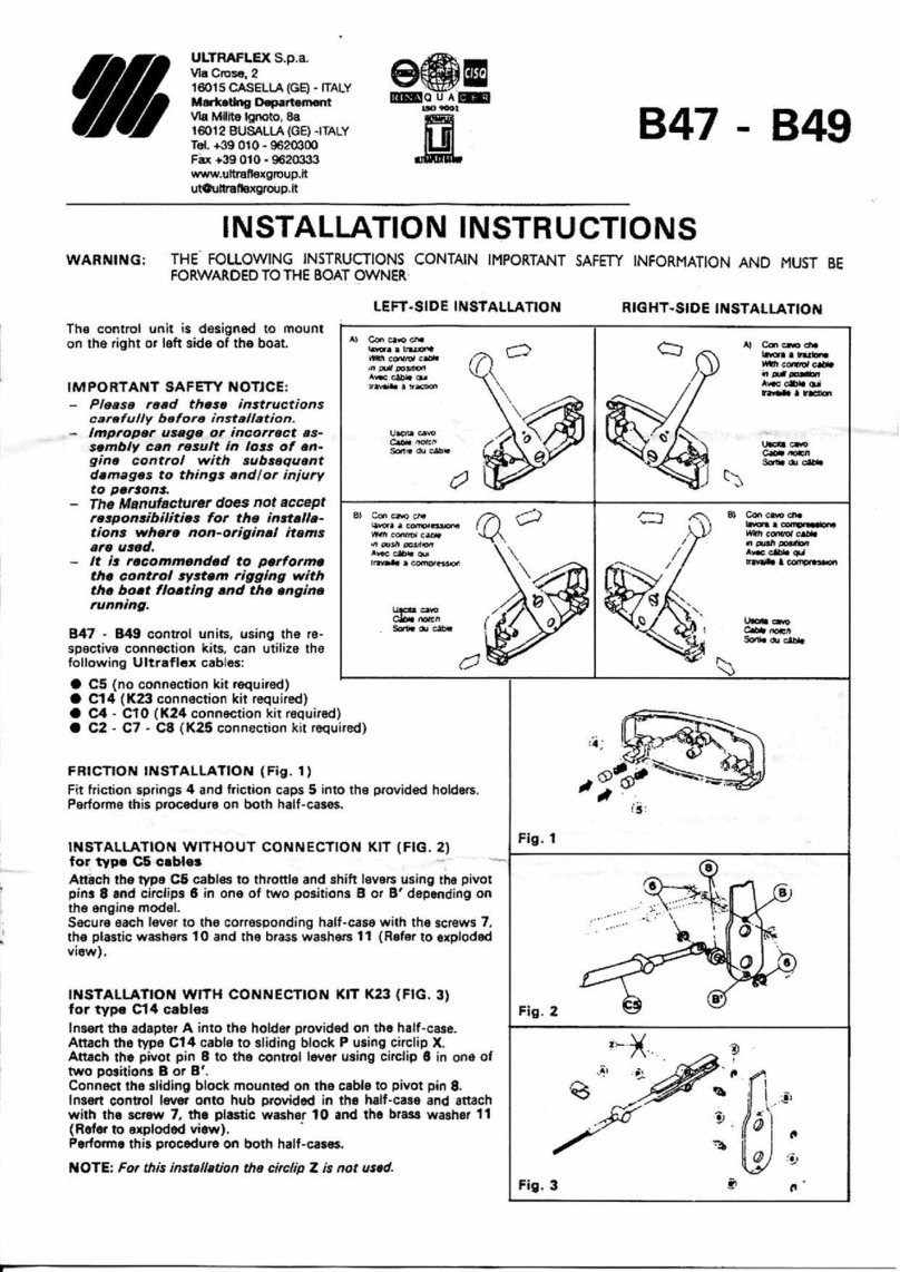
Ultraflex Power A Mark II User manual

PARTNER
ITALIANO
(Dr. No.28394/a16/02/2015)
ELECTRONICCONTROLSYSTEM
R
ENGLISH
Owner'smanual

DearCustomer,
We wouldliketo thankyoufor choosingan ULTRAFLEX product.
ULTRAFLEX hasbeenaleader insteeringsystemsforpleasureandprofessionalboatsfor manyyears.
ULTRAFLEX productionissinceeversynonimousof reliabilityandsafety.
All ULTRAFLEX productsare designedandmanufacturedtoensurethebestperformance.
To ensure yoursafety andto maintainahighquality level, ULTRAFLEX productsare guaranteedonlyif
theyareusedwithoriginalspareparts.
ULTRAFLEX and UFLEX QualityManagementSystemsare certifiedCISQ-IQNet bytheItalianShipping
Registry(RINA),inconformitywiththeUNIENISO9001:2008 rule. ULTRAFLEX certificationNo.6669/02/S
(former420/96). UFLEX certificationNo.8875/03/S.
Thequality managementsysteminvolvesall thecompanyresourcesandprocessesstartingfromthe
design,inorderto:
- ensure productqualitytothecustomer;
-maintainandimprove thequality standardsconstantly;
-pursueacontinuous process improvementto meet themarket needsandto increasethecustomer
satisfaction
ULTRAFLEX EnvironmentalManagementSystemiscertifiedCISQ-IQNet bytheItalianShippingRegistry
(RINA),inconformitywiththeUNIENISO14001rule. ULTRAFLEX certificationNo.EMS-1282/S.
Productsforpleasure boatsare constantlytestedtochecktheirconformitywiththe2013/53/EU.
ULTRAFLEX S.p.A.
ULTRAFLEX
16015Casella(Genova)Italia -ViaCrose,2
"ULTRAFLEX hasover 80 yearsof experience inthemarineindustry andisaworldleader intheproduction
ofmechanical,hydraulicandelectronicsteeringsystems,controlboxesandsteeringwheelsforany
kindof pleasure,fishingor commercialboats.
Thekey factorswhichexplaintheincreasingsuccess of ourproductsall over theworldare thereliability
of ourproductsandthebefore andafter saleservice,thequality of thecompanyorganizationandof the
humanresourcesandthecontinuousspendinginresearchanddevelopment".
ENGLISH

Owner'smanual
ULTRAFLEX
ENGLISH
POWERAMK2 -page 3 of36
TABLEOFCONTENTS
DOCUMENTREVISIONS....................................................................................................................4
MANUALUSEANDSYMBOLSUSED......................................................................................5
INFORMATIVE LETTER................................................................................................................................6
WARRANTY................................................................................................................................6
SECTION1-PRODUCTDESCRIPTION
1PRODUCT DESCRIPTION...................................................................................................................................7
SECTION2-USE
2.1 CONTROL DESCRIPTION...............................................................................................................9
2.2 OPERATIONOFTHECONTROLSTATIONLEVERS......................................................10
2.3 SYSTEMSTART................................................................................................................................................11
2.3.1 SYSTEMPOWER SUPPLY.........................................................................................................11
2.3.2 PANEL KEY ENABLING.........................................................................................................................11
2.3.3 ENGINESWITCHINGON.........................................................................................................12
2.3.4 CONTROLENABLING.........................................................................................................12
2.3.5 MULTIPLECONTROLSTATIONS.............................................................................................13
2.4 USEMODES......................................................................................................................................................14
2.4.1 WARMUPMODE............................................................................................................................14
2.4.2 AUTOSYNCMODE.................................................................................................................................15
2.4.3 HIGH-IDLE MODE................................................................................................................................16
2.4.4 TROLL MODE.......................................................................................................................................17
2.4.5 DOCKINGMODE..............................................................................................................................18
2.4.6 PANELBRIGHTNESSADJUSTMENT.................................................................................................19
SECTION3-WARNINGSANDALARMS
3.1 CONTROLSTATION.........................................................................................................................................21
3.2 V-THROTTLE,I-THROTTLE,PWM-THROTTLE,SAEJ-THROTTLE.............................................................23
3.3 SHIFTUNIT.......................................................................................................................................................24
3.4 MECHANICAL ACTUATOR USEDASTHROTTLE..........................................................................................26
3.5 MECHANICAL ACTUATOR USEDASSHIFT..................................................................................................28
3.6 CONTROL UNIT.................................................................................................................................................30
SECTION6-DISMANTLING
6.1 DISMANTLING..................................................................................................................................................34
ENCLOSURES
SECTION5-MAINTENANCE
5.1 ROUTINEMAINTENANCE................................................................................................................................33
5.1.1 CLEANING.........................................................................................................................................................33
5.1.2 ONEMONTHAFTER PRODUCT INSTALLATION...........................................................................................33
5.1.3 EVERY THREE MONTHS..................................................................................................................................33
5.1.4 EVERY YEAR.....................................................................................................................................................33
5.2 EXTRAORDINARY MAINTENANCE..................................................................................................................33
SECTION4-SAFETYWARNINGS
4.1 SAFETY STANDARDS DURINGINSTALLATIONAND USE..........................................................................32
4.2 CLOTHING.........................................................................................................................................................32

Owner'smanual
ULTRAFLEX
page 4 of36-POWERAMK2
ENGLISH
DOCUMENTREVISIONS
Rev. Date Revisiondescription
002/09/2011 Firstedition

Owner'smanual
ULTRAFLEX
ENGLISH
POWERAMK2 -page 5 of36
In thismanualthefollowingsymbols are usedto ensure theuser safety andto guarantee thecorrect
productworking:
MANUALUSEANDSYMBOLSUSED
THEINSTALLATIONAND MAINTENANCE MANUAL isthedocumentaccompanyingtheproduct fromsaleto
replacementanddischarge.Themanualisanimportantpartoftheproductitself.
Itisnecessaryto readcarefullythemanual,beforeANYACTIVITY involvingtheproduct,handlingand
unloadingincluded.
STERN
BOW
STARBOARD PORT
Thepictureasideexplainsthemeaningofsome
nauticalwordscontainedinthismanual.
DANGER Immediate hazardswhichCAUSEseverepersonalinjuryordeath.
WARNING
CAUTION
Thesymbolasideindicatesall theoperations whichmustbecarriedout
byqualifiedorskilledstaff,inordertoavoidhazards.
Werecommendtrainingthestaffinchargeof theproductinstallation
andcheckingtheirknowledge.
NOTICE Importantinformationfor thecorrect installationandfor maintenance,that
doesnot causeanydamage.
Denotesthat ahazardexistswhichcanresultininjury or deathifproper
precautions are not taken.
Denotesareminderofsafety practicesordirectsattentiontounsafe
practiceswhichcouldresultinpersonalinjury or damageto thecraft or
componentsor totheenvironment.

Owner'smanual
ULTRAFLEX
page 6 of36-POWERAMK2
ENGLISH
WARRANTY
TECHNICALASSISTANCE SERVICE
INFORMATIVELETTER
UFLEX S.r.l.
ViaMilite Ignoto,8A
16012 Busalla(GE)-Italy
Ph.: +39.010.962.0239(Italy)
Ph.:+39.010.962.0244 (abroad)
Fax:+39.010.962.0333
Email: ut@ultraflexgroup.it
www.ultraflexgroup.it
North-South-CentralAmerica:
UFLEX USA
6442ParklandDrive
Sarasota,FL34243
Ph.:+1.941.351.2628
Fax:+1.941.360.9171
Email: uflex@uflexusa.com
www.uflexusa.com
Thisinstallationandmaintenance manualisanintegrantpart of theproduct andshouldbeeasilyavailable
tostaff inchargeofuseandmaintenance.
Theuser mustknow thecontentof thismanual.
ULTRAFLEX declinesallresponsibility for possiblemistakesinthismanualdueto printingerrors.
Althoughthemainfeaturesof thetypeof product describedare not subject to change,ULTRAFLEX Company
reservestherightto modify anyparts,detailsandaccessoriesitdeemsnecessary to improvetheproduct
orformanufacturingor commercialrequirements,at anytimeandwithoutbeingobligedto updatethis
manualimmediately.
ALLRIGHTSARE RESERVED.Publishingrights,trademarks,part numbersandphotographs of ULTRAFLEX
productscontainedinthismanualare ULTRAFLEX property.Great care hasbeentakenincollectingand
checkingthedocumentationcontainedinthismanualtomakeitascompleteandcomprehensibleas
possible.Nothingcontainedinthismanualcanbeinterpretedaswarranty either expressedor implied-
including, not inarestrictedway,thesuitability warranty for anyspecialpurpose.Nothingcontainedinthis
manualcanbeinterpretedasamodificationor confirmationof thetermsofanypurchasecontract.
Toensurethecorrectproductandcomponentworking,theproductmustbeinstalledbyqualifiedstaff.
In theeventof partdamageormalfunction,pleasecontact thequalifiedstafforourTechnicalAssistance
Service.
WARNING
ULTRAFLEX guaranteesthat itsproductsare well designedandfree frommanufacturingandmaterialdefects,
foraperiodoftwo yearsfromthedate of manufacturing.
Fortheproductswhichareinstalledandusedonworkingorcommercialboatsthewarrantyislimitedto
oneyearfromthedateofmanufacturing.
Ifduringthisperiodtheproduct provestobedefective dueto improper materialsand/or manufacture,the
manufacturerwillrepairor replace thedefective partsfreeof charge.
Direct orindirectdamageisnotcoveredbythiswarranty.Inparticularthecompanyisnotresponsibleandthis
warranty willnot cover thedamageresultingfromincorrect installationor useof theproduct(exceptfor
replacementorrepairof defective partsaccordingto theconditions andtermsabove).
Thiswarrantydoesnotcover theproductsinstalledonrace boatsor boatsusedincompetitions.
Thedescriptionsandillustrationscontainedinthismanualshouldbeusedasgeneralreferenceonly.
For anyfurther informationpleasecontact ourTechnicalAssistance Service.
ULTRAFLEX steeringsystemcomponentsaremarkedaccordingto theDirective 2013/53/EU.
We remindyouthat only markedsteeringsystemsmustbeusedontheboatsmarked .

Owner'smanual
ULTRAFLEX
ENGLISH
POWERAMK2 -page 7 of36
1PRODUCTDESCRIPTION
Thesystemismadeupofaseriesof intelligentmoduleswhichcommunicateviaa
proprietaryCANbus.Theyaltogether controltheboatpropulsionengines,andatthesametimeallowthe
adjustmentoftheboatattitudestabilizers.
Theuser cancontrolthethrottleandtheshift of theboat enginebymeans of thecontrolstation,whichwill
beequippedwithoneortwoleversaccordingtothenumber ofenginesontheboat.
Thetrimsto controltheattitudestabilizerscanbelocatedontheport lever (theonlyoneincaseof single-
engineboats).
CONTROLSTATION
TWIN-ENGINE
WITHTRIM
TWIN-ENGINE
WITHOUTTRIM
SINGLE-ENGINE
WITHTRIM
SINGLE-ENGINE
WITHOUTTRIM
CONTROLUNIT
Theboatcanbe equipped withmaximum fourcontrolstations;theuser will be allowed by thesystem
tocontroltheboatusingonlyonestation atatime.
Thesystem isalwaysprovided with acontrol unitusedtocarryoutcalibrations
anddiagnostic.
Theother componentsvaryaccordingtotheapplication: whenever amechanicalinterface(itmaybe a
throttleor ashift) mustbe controlled,amechanicalactuator has tobe used.
MECHANICALACTUATOR

Owner'smanual
ULTRAFLEX
page 8 of36-POWERAMK2
ENGLISH
If thethrottleiselectronic, there will be ananalogueor digitaldedicated interface.
Throttles with under-voltage analogueinterfaceor PWMare provided withtheV-throttleunit.
Similarly, throttles withunder-currentanalogueinterfaceare provided withtheI-throttleunit,which is
externallyidenticaltotheV-throttleunit.
V-THROTTLE UNIT
If thethrottleisprovided with aCANbusdigitalinterfaceaSAEJ-throttleor aNMEA-throttleunitmust
be used.
SAEJTHROTTLEUNIT
Incase ofelectric shifts,ashift unitallowingthegearsolenoidcontrolisused.
SHIFTUNIT
Thepowerunithas thefunctionofsupplyingthesystemdevices (shift unitandmechanicalactuator)with
power.
POWERUNIT

Owner'smanual
ULTRAFLEX
ENGLISH
POWERAMK2 -page 9 of36
2.1Controldescription
2USE
Thepicture below showsanenlargementof theuser interface locatedonthecontrolstations.Theinterface
isthesamefortwin-enginestationswithor withouttrim switches.
ABCD
1
E
3
G
F
2
H
4
4keysand8LEDindicatorsare locatedontheuser interface.
Thecontrolstationisprovidedwithabuzzersignallingtheoperatingconditionandpossiblefailures.
Item Description Function
1
Key CTRL Enablinganddisablingofthecontrolstation
2
Key WARM Enablinganddisablingofthrottlemodeinneutral position
3
KeyHIGH IDLE Enablinganddisablingof thehigh idleandalarmsilencing
4
Key SYNC Enablinganddisablingoftheenginerevolutionsynchronizingand
dockingmodes
A
GREENLED Enablingof theport stationor single-engine
B
REDLED
Enablingof thethrottle modeinneutral positionfor theport
engine(or single-engine).
Failuresignallingreferringtotheport engine(or single-engine)
C
REDLED
Enablingof thethrottlemodeinneutral positionfor thestarboard
engine.
Failuresignallingreferringtostarboardengine.
D
GREENLED Starboardstationenabled
E
GREENLED Troll modeenabled
F
REDLED Highidlemodeenabled
G
GREENLED Syncmodeenabled
H
REDLED Dockingmodeenabled

Owner'smanual
ULTRAFLEX
page 10 of36-POWERAMK2
ENGLISH
2.2Operationof thecontrol stationlevers
In caseof single-engineboats,thecontrolstations are providedwithalever (theport lever);incaseof twin-
engineboats,thecontrolstationsareprovidedwithtwo levers:theport lever controlstheportengineand
thestarboardlever controls thestarboardengine.
Thepositionof theleversdeterminestheoperatingconditions of theengines.Eachlever anglegivesa
propershift positionandthrottlevalue.
Inthetwin-enginecontrolstation,theleversworkinthesameway.
NEUTRAL FORWARDGEAR
minimumenginespeed
FORWARDSTROKE
Engine speedcan beadjusted
from aminimumtoamaximum
value
FORWARDGEAR
Full speed
REVERSEGEAR
minimumenginespeed
REVERSESTROKE
Engine speedcan be
adjustedfrom aminimum
toamaximum value
REVERSEGEAR
Full speed
80°
80°
15°
15°
NEUTRAL -Whenthelever isincentralposition,theengineisinneutralandat idle.
DETENTFORWARD-Whentheleverhasaforwardinclinationof15°therelevantshiftisenabledandputs
into forwardgear.Thethrottleremainsatidle.
DETENTREVERSE-Whenthelever hasareverseinclinationof 15°therelevantshift isenabledandputsinto
forwardgear.Thethrottleremains atidle.
ACCELERATION-Whenthelever inclinationangleishigher than15°theengineaccelerationstarts.The
maximumaccelerationvalue(fullspeed)isobtainedwithalever inclinationof 80°.
Thethrottledetentforwardanddetentreversearecontrolledinasimilar way.
Thethrottleanswerwithrespecttothelever anglecanbeselectedbytheuserduringcalibration.
RETURNTONEUTRAL-Whentheleverisputinthecentre again,thethrottleisatidleandtheshiftisin
neutralposition.Thecontrolstationsignalsthattheleverhasreachedtheneutralpositionwithashort
sound.

Owner'smanual
ULTRAFLEX
ENGLISH
POWERAMK2 -page 11 of36
2.3Systemstart
Firstofallsupplythesystemwithpowerbymeansof thethermalswitchlocatedonthepowercord.The
switchmustbeset totheONposition(switchclosed).Iftherearetwopowercordsand,therefore,two
thermalswitches,makesure that bothof themare set to theONposition.
2.3.1System powersupply
Tocorrectlystart thesystem, follow thestepsbelow:
Thepanelkeysoftheengineofeachboatmustbeenabled.
Whentheenginepanelkeycontactisclosed(key enabled)thecontrolstationsignalstotheuserthatthe
boat canbecontrolledwithaLEDflashingandanintermittentsoundsignalling.
In single-engineboats,theflashingLEDistheoneshowninthepictureaside.
Thesameoccursintwin-engineboats,iftheport enginekeyisenabled.
Duringthisconditionthesystemcannot becontrolled: anylever movementhas
noeffectsontheengine;therefore,pressureontrimswitchesisignored.
In twin-engineboats,ifthestarboardenginekey isenabled, theflashingLED
willshowthatthestarboardstationhasbeenenabled(see pictureaside).
Inthiscasetoo,thesystemcannot becontrolled.
In twin-engineboats,whenbothenginekeysare enabled, bothLEDswill flash
showingthatthestationhasbeenenabled, asshowninthepicture aside.
Inthiscasetoo,thesystemcannot becontrolled.
Iftheenginekey isdisabledandthecontroliswaitingfor thestationenabling,
therelevantLEDwill switchoff showingthat therelevantsideisdisabled.
2.3.2Panel keyenabling

Owner'smanual
ULTRAFLEX
page 12 of36-POWERAMK2
ENGLISH
Itispossibleto switchontheenginesifthefollowingconditions aremet:
1)Thelevermustbeset totheneutralposition;aclickisheard
whenplacingthelever verticallyinorder to reachsuchaposition.
Amarkonthecontrolstationpackageshowstheleverneutral
position.
2)Thekey mustbeenabled;
3)Nofailuremustpreventtheshiftfrombeingsettotheneutral
positionandthethrottlefrombeingat idle.In thiscaseaproper
acoustic/visualmessagewill warntheuser andtheproblemwill
appearonthecontrolunitdisplay.
2.3.3Engineswitchingon
Theprevious considerations are validforbothenginesincaseof twin-engineinstallations.
Theenginestartinhibitionisensuredonlyiftheproper switcheshavebeenconnectedasindicatedinthe
installationmanual.NOTA
NOTICE
DANGER
2.3.4Controlenabling
Tocontrolthesystemitisnecessarytoenabletherequiredcontrolstation.
To carry outthisoperation,push keyCTRLonce ifthefollowingconditions are
met:
1)Thelevermustbeinneutralposition.
2)Thepanelkey mustbeenabled.
3)Nofailuremustpreventthecontrolstationfromoperating.
4)Theother controlstations aredisabled.
Whenthecontrolstationisenabled,therelevantgreenLEDlightsupandthe
buzzerturnsoff.
Thecontrolstationcanbepartiallyenabledorcannotbeenableddepending
ontheconditions describedabove,since they couldapplyto asingleengineor
to noneof them.
Ifthecontrolstationisenabledpartially,thegreenLEDcorrespondingto the
disabledpart of thesystemwillkeeponblinkingandthebuzzer will keepon
sounding.

Owner'smanual
ULTRAFLEX
ENGLISH
POWERAMK2 -page 13 of36
Tocontroltheother sidetoo,checkthepointsdescribedabovethenpresskeyCTRL.
Iftheenginekey isdisabledwhilethestationisenabled, therelevantLEDwill switchoff indicatingthat that
sideisdisabled.
Ifthere isafailure,thecontrolstationwill produce anacousticsignalandthe
redLEDswill blink:theleft LEDfor theportengine(or single-engineboats)
andtherightonefortherightengine.
Eachfailure hasgotitsownalarmcodewithadifferentsoundsequence.
Thedisplayonthecontrolunitwill providetheuserwithmore information
aboutthekindofalarmenabled.
Ifmorecontrolstations are installedontheboat,itispossibleto useonlyonestationatatime,therefore
onlyonecontrolstationatatimecanbeenabled.
Tochangestation,keepkeyCTRLpressedforafewsecondstodisablethecontrolledstation.
Thestationcanbedisabledif:
1)Theleverisinneutralposition.
2)Nofailure preventsthecontrolstationfromoperating.
Iftheseconditons occur,thecontrolstationwillbedisabledandtheenablingprocedure describedabove
canbecarriedout.
2.3.5Multiple control stations

Owner'smanual
ULTRAFLEX
page 14 of36-POWERAMK2
ENGLISH
2.4Usemodes
Thismodeallowstheuserto varytheenginespeedwiththeshift inneutralposition.
Toenablethismodethefollowingconditionsmustbemet:
-Thestationmustbeenabled.
-Thelevermustbeinneutralposition.
-Theremustbenofailuresthat couldcauseproblemsduringtheenablingofthismode.
ToenabletheWARM-UPmode,presstheproper
keyontheuserinterface.
TheWARMUPred LEDswill lightupwhenthemode
isenabled.
In single-enginesystems,onlytheleft LEDwill light
up.
In twin-enginesystemstheWARM-UPmodecanbeenabledonlyononeengine:theproper LEDwill indicate
theengineonwhichthismodeisenabled. Inthiscasepay great attentionnotto accidentallystart the
enginewhichisnot inWARMUPmode.
TheWARM-UPmodeturnsoffwhenthecontrolledstationisdisabledanditdoesnotturnonwhenthe
stationisenabledagain.
To disabletheWARM-UPmodethefollowingconditionsmustbemet:
- Thelevermustbeinneutralposition.
-Theremustbenofailuresthatcouldpreventthismodefrombeingdisabled.
To disabletheWARM-UPmode,press key WARM-UP.TheWARMUPredLEDsswitchoff indicatingthat the
modehasbeendisabled,
In single-enginesystems,onlytheleft LEDwill switchoff.
2.4.1WARMUP mode
After enablingthedesiredstation,itispossibleto putintoreverseorforwardgear andadjusttheengine
speedbymovingthelevers.
Similarly,ifthisfunctionhasbeensetup, thetrim attitudecanbemodifiedbymeansof thetwo trim
switchesontheportlever.
Moreover there are somefunctions that modify thecontrolnormaloperation:WARM-UP,AUTOSYNC,HIGH-
IDLE,DOCKING,TROLL.
WARNING

Owner'smanual
ULTRAFLEX
ENGLISH
POWERAMK2 -page 15 of36
In twin-enginesystemstheWARM-UPmodecanbedisabledonlyononeengine:theproper LEDwill
indicatetheengineonwhichthismodeisenabled.
Itispossiblethat theWARM-UPmodeisenabledonlyononeengineandthecontrolstationmeetsthe
conditionslistedpreviously(leversinneutralpositions,nofailure):inthiscase,whenpressingkeyWARM
again,thismodewillbedisabledontheengineonwhichitwasenabledandviceversa.
To disabletheWARM-UPmodeonboththeengines,doasfollows:
-Putthelever of theengineinWARM-UPmodeto theforwardposition.
- Press keyWARM-UP.
-Movetheaforementionedlever to theneutralposition.
-Press key WARM-UPagain.
WARNING
Thismodeallowstheautomaticsynchronizationof theenginespeedof boththeboat propulsors:thestarboard
enginewilladjustitsrevolutionsaccordingtotheportengine.
Thismodecanbefoundontwin-enginesystemsonly.
Thismodecanbeenabledifatleastonestationiscontrolledregardlessoftheleverpositionbypressing
keySYNContheuser interface.
ThegreenSYNCLEDwill lightupwithoutflashing
indicatingthat thismodehasbeenenabled.
Underthiscondition,theenginesynchronization
occursifthefollowingrequirementsaremet:
-Thedifference ininclinationbetweenthelevers
islower than15°.
-Thethrottlepercentageof boththeengines(which
isgivenbythelevers)ishigher thanthe20%of
thetotalamount.
-Boththeenginesareputintoforwardgear.
TheSYNCLEDwill blinkwhentheenginesaresinchronized.
TheenginesynchronizationisenabledonlywhentheproperLEDisblinking.
Whenoneof theprevious conditions isnot met anymore,thesynchronizationis
disabledbuttheSYNCmodeisstill on.Whenalltheconditionsaremet,the
synchronizationcanbeenabledagain.
TheSYNCLEDontheuserinterfacelightsupwithoutblinkingwhenthe
synchronizationisdisabled.
To disabletheAUTOSYNCmode,press key SYNC:thegreenSYNCLEDswitches
off.
Whenchangingthecontrolstation,theAUTOSYNCmodeisdisabled.
2.4.2AUTOSYNCmode
WARNING

Owner'smanual
ULTRAFLEX
page 16 of36-POWERAMK2
ENGLISH
TheHIGH-IDLE modeallowstheusertoincreasetheengineidlespeed.
Toenablethismodethefollowingconditionsmustbemet:
-Thestationmustbeenabled.
-TheDOCKINGmodemustnot beenabled.
-Theremustbenofailuresthat couldpreventthismodefrombeingenabled.
To enabletheHIGH-IDLE modejustpress theproper
keyontheuserinterface.
Theproper redLEDwill lightupindicatingthat the
HIGH-IDLE modeison.
In theengineaccelerationcurve thehighidlevalue
isset astheidlespeed.
To disabletheHIGH-IDLE mode,press theproper key ontheuser interface:theHIGH-IDLE redLEDswitches
offwhenthismodeisdisabled.
In atwin-enginesystemtheHIGH-IDLE modecanbeenabledononeengine
only.In thiscasetheHIGH-IDLE redLEDwill blink.
TheHIGH-IDLEmodeisdisabledwhenchangingthecontrolstation.
2.4.3HIGH-IDLEmode
WARNING

Owner'smanual
ULTRAFLEX
ENGLISH
POWERAMK2 -page 17 of36
TheTROLLmodeallowstheusertocontrolthetrolling-valve ofeachengine.
Toenablethismodethefollowingconditionsmustbemet:
-Thestationmustbeenabled.
-Alltheotherfucntions mustbedisabled.
-Theleversmustbeinneutralposition.
-Theremustbenofailuresthat couldpreventthismodefrombeingenabled.
ToenabletheTROLLmode,keepkeyHIGH-IDLE
pressedforafewseconds.Themodeisenabled
whenthekeyisreleased.
Theproper greenLEDwill blinkindicatingthat the
TROLL modeison.
To disabletheTROLL mode,keeptheproper key
ontheuserinterfacepressedforafewseconds:
theTROLL greenLEDwill switchoff.
Inatwin-enginesystem,theTROLLmodecannot beenabledononeengineonly.
TheTROLLmodeisdisabledwhenchangingthecontrolstation.
2.4.4Troll mode
WARNING

Owner'smanual
ULTRAFLEX
page 18 of36-POWERAMK2
ENGLISH
TheDOCKINGmodeallowstheuser to reduce themaximumenginespeedwithoutreducingthelever
angulartravel.
TheDOCKINGmodeallowsahighersensitivityonthrottle,thereforeitissuitablefordocking.
Toenablethismodethefollowingconditionsmustbemet:
-Thestationmustbeenabled.
-HIGH-IDLE andTROLL modesmustbeoff.
- Theremustbenofailuresthat couldpreventthismodefrombeingenabled.
To enabletheDOCKINGmode,keepkey SYNC
pressed; themodewill beenabledwhenthekey is
released.
Theproper redLEDwill lightupindicatingthat the
DOCKINGmodeison.
In theengineaccelerationcurve,themaximum
enginespeedisset ashalfof thenormalspeed.
To disabletheDOCKINGmode,presstheproper
key ontheuser interfacefor afew seconds:the
DOCKINGredLEDwill switchoff.
Inatwin-enginesystem, theDOCKINGmodecanbeenabledononeengine
only.In thiscasetheDOCKINGredLEDwill blink.
TheDOCKINGmodeisdisabledwhenchangingthecontrolstation.
2.4.5Dockingmode
WARNING

Owner'smanual
ULTRAFLEX
ENGLISH
POWERAMK2 -page 19 of36
Itispossibleto increaseor reduce theLEDbrightness ontheuser interface bykeepingkey WARMpressed
forafewseconds.
Eachsecondthekey iskeptpressed, theLEDbrightness will increaseupto the
maximumvalue.By keepingthekey pressed, thebrightness will bereducedto
theminimum,thenincreasedagainuntilthekeyisreleased.
To changetheLEDbrightness,itisnot necessary to enablethestation.
TheLEDbrightness will bechangedonlyonthestationwhichwascontrolledby
means of key WARM.
Thenew brightness valuewill bemantaineduntilthesystemisswitchedoff bymeans of theproper thermal
switch.
2.4.6Panelbrightnessadjustment

Owner'smanual
ULTRAFLEX
page 20 of36-POWERAMK2
ENGLISH
3WARNINGSAND ALARMS
Thesystemwarns theoperator aboutfailuresbymeans of thecontrolstation(visualand
acousticsignals)andthecontrolunitdisplay.
ThecentralredLEDsontheuserinterface show failures.
Abuzzer insidethelever producesasoundthat canbestoppedbykeepingkey
HIGHIDLE pressedfor afew seconds.
Novisualsignals will beshownwhenanalarmisstopped.
Failuresare dividedinto two categories:warnings(not severe failures)and
errors(severefailures).
Theleft redLEDwill indicate afailure ontheport engine(or onsingle-engineboats)andtherightonefor
thestarboardengine.
Toacknowledgethefailureitisnecessarytoreadtheerrorcodeonthecontrolunitdisplay.
Theerrorisshownonthediagnosticmainpage.
Insingle-enginesystems,iftherearenoerrors,thispageisdisplayedasfollows:
Ifthere isanerror,indication"ER"isdisplayedasfollows:
Intwin-enginesystems,iftherearenoerrors,thispageisdisplayedasfollows:
Ifthere isanerror,indication"ER"isdisplayedasfollows:
IndicationER canbepresentononesideonly.Inthiscase,theerrorisdetectedontherelevantside(the
firstlinereferstoport,thesecondoneto starboard).
Formoreinformationaboutthefailureitisnecesarytoconsulttheitemdiagnosticpage.
Toscrollthediagnosticpagespresstherightarrowofthenavigationswitch.
To select thedesireditems(markedbyanasteriskonitsright) press key OKat thecentre of thenavigation
switch.
Thefollowingpagesshow onetablefor eachdiagnosticpageonthecontrolunitthat canhelpto acknowledge
thefailure.
Table of contents
Other Ultraflex Controllers manuals