5
illing the tank
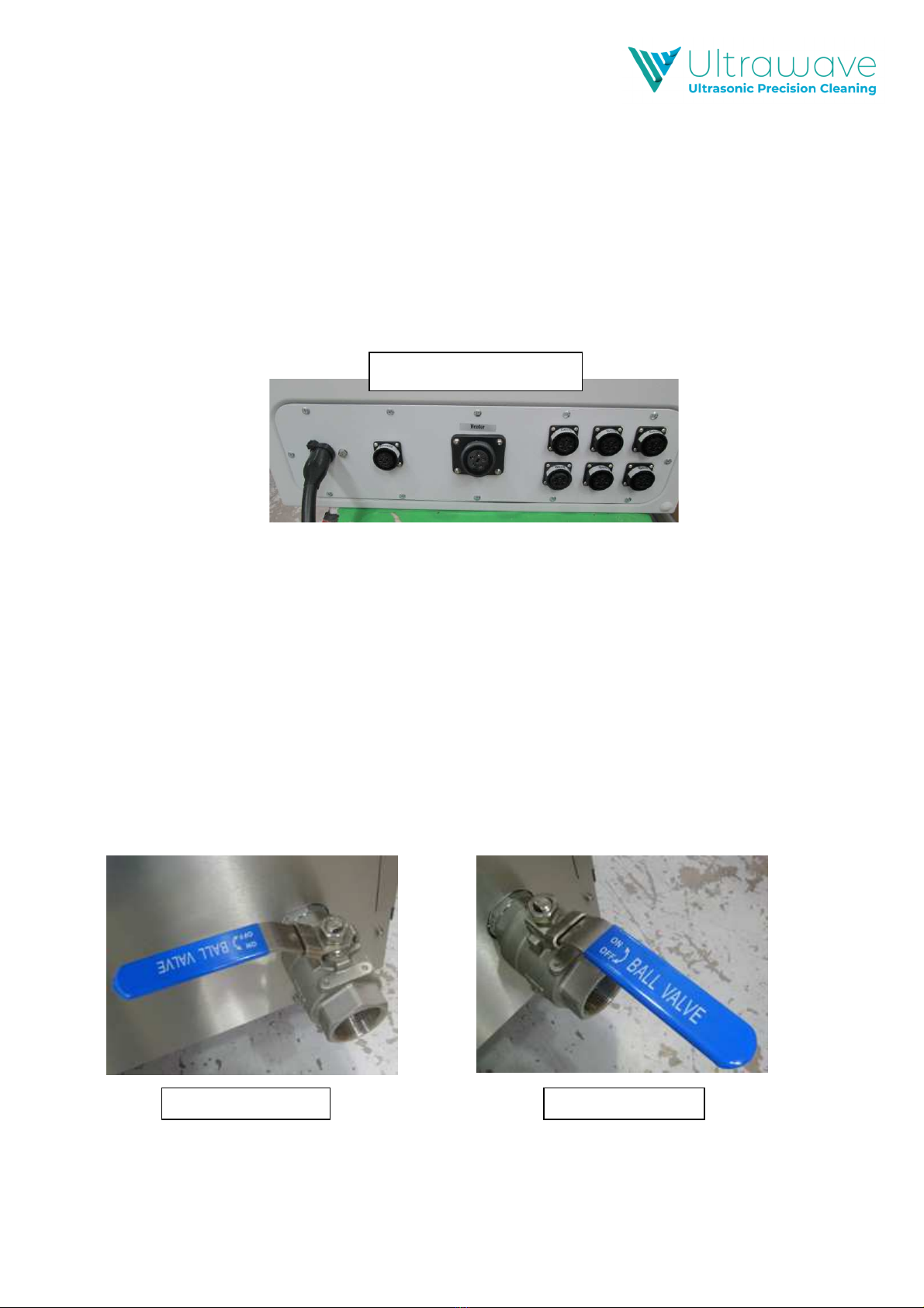
Ensure both tank drain valves are in the closed position
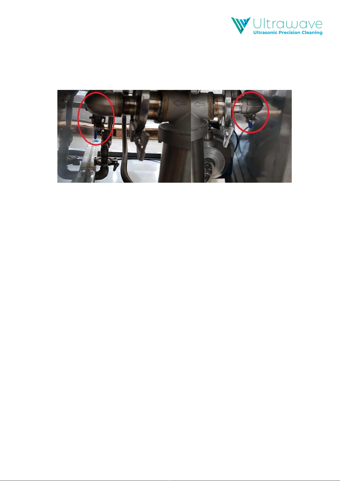
Ensure both recirculation isolation valves are in the open position
Fill the weir area with cold or warm water as required
Wait until the weir area is full to the top of the weir divider plate weir
Confirm water is now filling the process area via the recirculation system at the bottom
of the weir divider plate:
If no water is visible in the process area, recheck the position of the recirculation
filter isolation valves
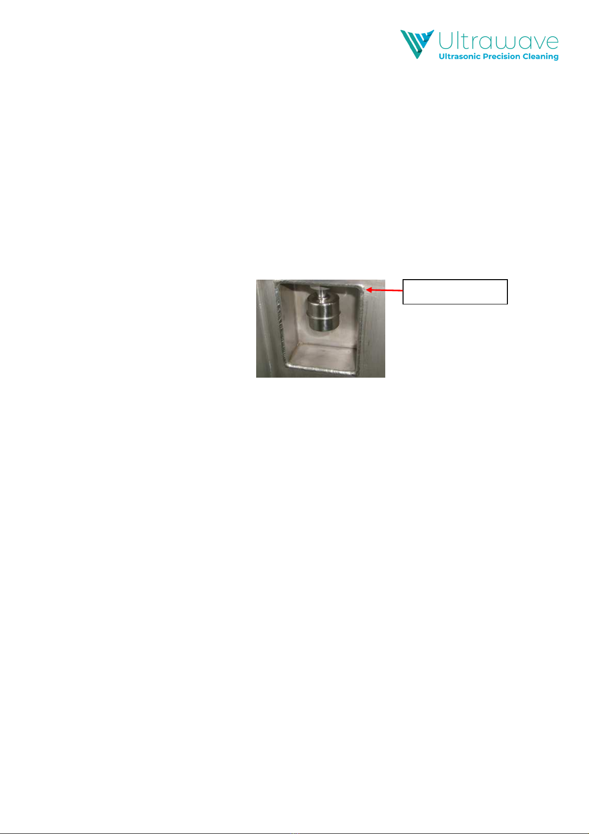
If water is visible, move the hose to fill the process area until the upper float
pocket is covered.
he Argon Series of units are fitted with two float level sensors. he lower float allows
the heaters to operate, and the upper float allows the ultrasonic and recirculation pump
to operate. Please ensure the fluid reaches over the top level sensor or the ultrasonics
will not operate
Add the required dose of detergent (see pg. 14).
Quick Operating Guide
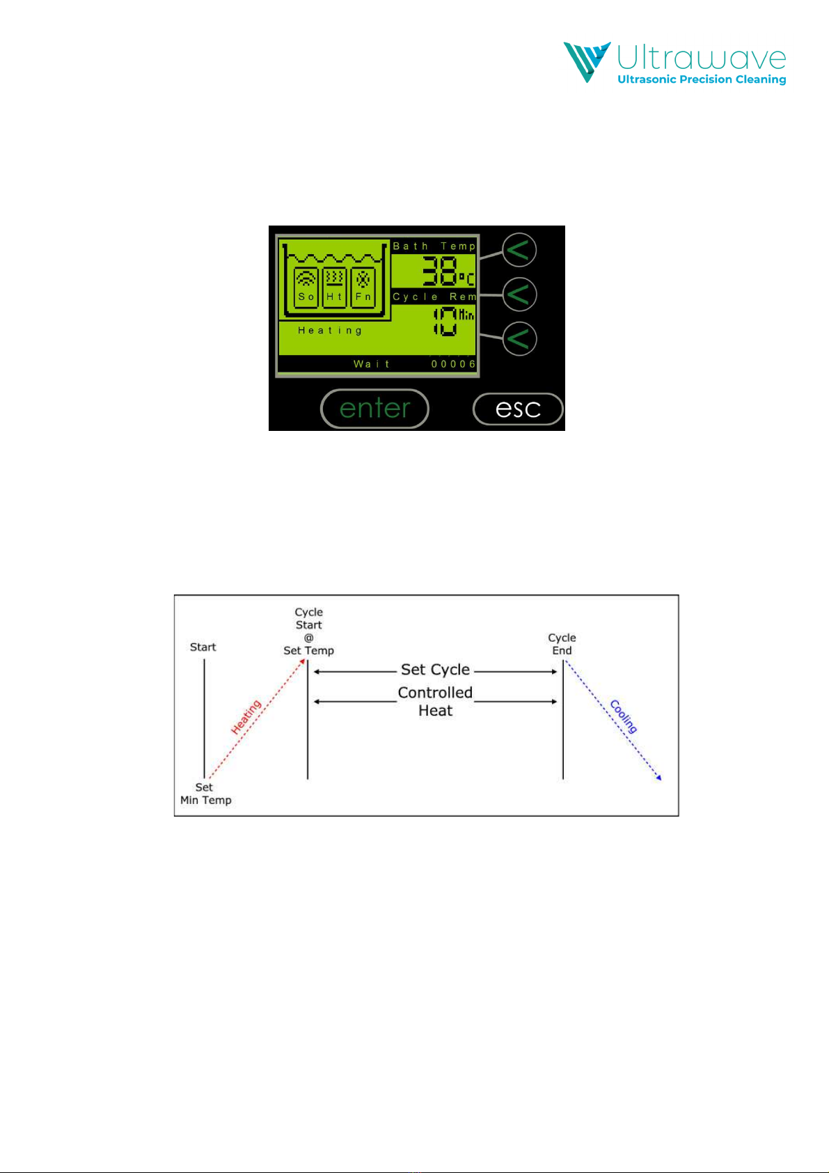
Switch on the machine via the switch at the front of the unit/control panel.
Press the “enter” key or the Start/Stop button to accept the programmed cleaning cycle
settings and start the cleaning cycle.
Pressing again will terminate the cycle.
At the end of the cycle, remove the basket from the bath and rinse the items under
clean running water.
REMEMBER
-Always ensure the liquid is above the float level sensor when in operation.
-Do not put hot water above 50°C into the tank.
-Always use the basket.
-Never expose hands to cleaning solutions.
-Never use toxic, flammable, acidic, caustic or corrosive solutions.
-Never breathe the fumes from strong solutions.
-Rinse the items in clean water once the cycle is complete.
Subjecting the Argon Series ultrasonic cleaning system to improper treatment or
misuse will invalidate the warranty.
Minimum Level