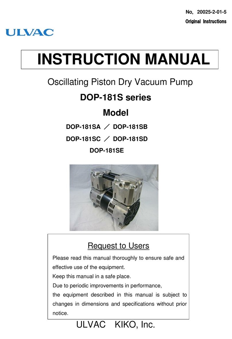
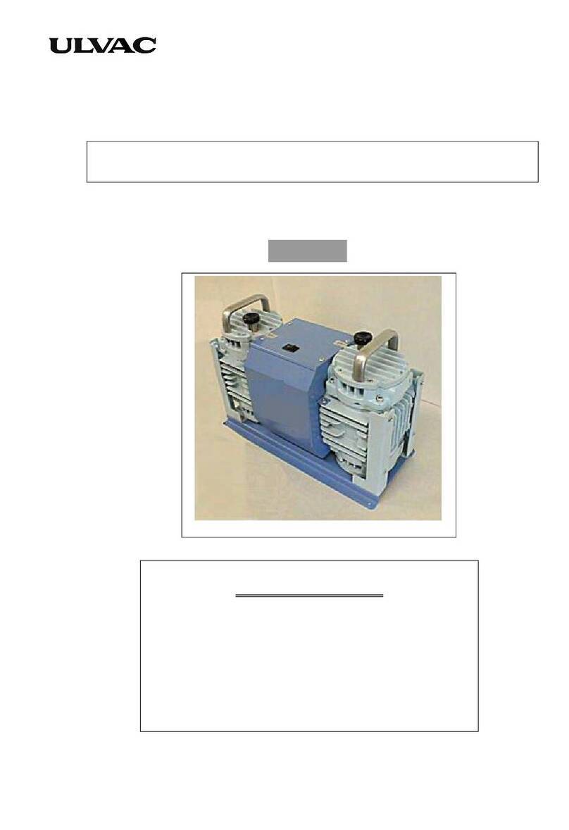
Ulvac CRYOPUMP CRYO-U Series User manual

D/N.MA18A00E, 2022AL07 ULVAC CRYOGENICS INCORPORATED
CRYOPUMP
CRYO-U® SERIES
Instruction Manual
CRYO-U®18H
Export Control Policy
Vacuum pumps that pump nitrogen gas at pumping speed of 15000L/s or
more fall under row 2(35) of appended table 1 of Japan’s
Export Trade
Control Order, which is based on international export control regimes.
Also, when applying a refrigerator system to a cryocooler for optical
sensors, the cryocooler falls under row 10(2) of appended table 1 of Japan’s
Export Trade Control Order as well.
Customers must follow all related rules and regulations such as Foreign
Exchange and Foreign Trade Act and take appropriate
procedures when
exporting or re-exporting those products.


MZ0F001E,2013OR03 ULVAC CRYOGENICS INCORPORATED F-1
Introduction
Thank you for choosing our products. This instruction manual gives
information and precautions on handling, installation, operation, and
maintenance of the product.
This product is intended for use by qualified personnel who recognize shock
hazards and are familiar with the safety precautions required to avoid possible
injury. To ensure proper use of this product, read this instruction manual
carefully and keep this manual close at hand so that you can use for reference
during operation.
If you purchased our other products and/or optional devices with this product,
read relevant instruction manuals carefully.
1. About the personnel who are involved in handling our products
All personnel involved in handling our products should take a general safety
education and training that is officially accepted in the country where our product
is used. The personnel are also required to have specialized knowledge/skills and
qualification on the electricity, the machinery, the cargo handling, and the vacuum.
Especially, the personnel should be familiar with handling a cryopump in order to
use it safely. Since we offer a training session (which is subject to fees) as needed
for people who use cryopumps for the first time, please do not hesitate to contact
our Service Engineering Division to join the training session.
2. Warranty
2.1 Gratis warranty period and Warranty coverage
【Gratis warranty period】
Note that an installation period of less than one year after installation in your
company or your customer’s premises or a period of less than 18 months (counted
from the date of production) after shipment from our company, which is shorter, is
selected.
【Coverage】
(1) Failure diagnosis
As a general rule, diagnosis of failure should be done on site by customer.
However, ULVAC CRYOGENICS or our service network can perform this service
for an agreed fee upon the customer’s request. There will be no charge if the cause

F-2 ULVAC CRYOGENICS INCORPORATED
of the breakdown is found to be a fault of ULVAC CRYOGENICS.
(2) Damage during transportation
When damage by delivery/transportation is admitted, the product will be
repaired free of charge within the range of the guarantee expressed in the sales
contract.
(3) Breakdown repairs
There will be a charge for breakdown repairs, replacements and on-site visits
for the following seven conditions. In those cases the cost shall be your own
expense even though the product is within the warranty period.
①Breakdowns due to improper storage or handling, careless accident, software
or hardware design by the customer.
②Breakdowns due to modifications of the product without consent of the
manufacturer.
③Breakdowns due to maintenance of the product without authentic parts or
breakdowns resulting from using the product outside the specified
specifications of the product.
④Breakdowns due to contamination or corrosion caused by user’s use
conditions.
⑤Breakdowns due to natural disasters (such as fire, earthquake, flood,
lightning, salt damage, and so on) , environmental pollution, irregular voltage,
and /or usage of undesignated power source.
⑥Breakdowns that are outside the terms of warranty.
⑦Consumables and/or replacement service.
Since the above services are limited to within Japan, diagnosis of failures, etc are
not performed abroad. If you desire the after service abroad, please contact
ULVAC CRYOGENICS and consult us for details in advance.
2.2 Exclusion of opportunity loss from warranty liability
Regardless of the gratis warranty term, compensation to opportunity losses
incurred to your company or your customers by failures of ULVAC CRYOGENICS
products and compensation for damages to products other than ULVAC
CRYOGENICS products and other services are not covered under warranty.

MZ0F001E,2013OR03 ULVAC CRYOGENICS INCORPORATED F-3
2.3 Repair period after production is discontinued
ULVAC CRYOGENICS shall accept product repairs for seven years after
production of the product is discontinued.
3. Service Form
After the products are delivered, please fill out the following information in the
blanks. If you have any questions or technical problems, please feel free to contact
the nearest Customer Support Center or headquarters. Please refer to “Service
Network”.
Cryopump/Super trap Model :
Cryopump/Super trap Serial No. :
Refrigerator Model :
Refrigerator Serial No. :
Compressor Model :
Compressor Serial No. :
Temperature controller/Thermal display Model :
Temperature controller/Thermal display Serial No. :
Option Part Model :
Optional Part Serial No. :
4. Notes for repair and maintenance requests
We may decline your request for the repair or the maintenance of our products if
you refuse to give us information about the presence of the hazardous substance
and/or contaminant.
Also, please be aware that we do not accept liability for damages by the
contaminant, which might be caused during transportation to our office or the
nearest customer support center. To avoid such accident, please pay careful
attention to packing of the product
5.In case of breakdown and accident
When breakdown or accident occurs, we may ask for keeping the product on site
as it is or retrieving the product to investigate its cause. Also we may ask for
reporting the detailed process and/or the operating condition. When unidentified
malfunction was generated, please contact our Service Engineering Division or

F-4 ULVAC CRYOGENICS INCORPORATED
the nearest customer support center with reference to the chapter of Service
Network. We ask for cooperation about the above.
6.General Precautions
(1) It is strictly prohibited to duplicate, open, and transfer this instruction
manual or any of its parts to a third person without written permission from
ULVAC CRYOGENICS.
(2) Information in this document might be revised without a previous notice for
the specification change and the improvement of the product.
(3) If you have any questions or comments on this document, please do not
hesitate to contact us. The phone numbers of local customer support centers
are listed at the end of this manual.

MZ0F001E,2013OR03 ULVAC CRYOGENICS INCORPORATED F-5
Safety Considerations
Our products have been designed to provide extremely safe and dependable operation
when properly used. Following safety precautions must be observed during normal
operation and when servicing them.
CAUTION
WARNING
A warning describes safety hazards or unsafe practices
which could result in severe injury or loss of life.
Acaution describes safety hazards or unsafe practices which
could result in personal injury or equipment damage.
Toxic gas or chemicals used.
There is a risk of severe injury upon contact.
Corrosive chemicals used.
There is a risk of severe injury upon contact.
Flammable gas used.
There is a danger of fire or burn injury.
Explosive gas used.
There is a risk of fire or explosion.
Hazardous voltage .
Electric shock may cause severe injury or loss of life.
Hot heating part present.
There is a risk of burn injury.

F-6 ULVAC CRYOGENICS INCORPORATED
This page intentionally left blank

CRYO-U®cryopump instruction manual
TABLE OF CONTENTS
Safety Instructions・・・・・・・・・・・・・・・・・・・・・・・・・・・・・・・・・・・・・・・・・・ S-1
Disposal Consideration・・・・・・・・・・・・・・・・・・・・・・・・・・・・・・・・・・・・・・ IW-1
SECTION 1 Cryopump Description
1.1 The General・・・・・・・・・・・・・・・・・・・・・・・・・・・・・・・・・・・・・・・・・・ 1-1
1.2 Specifications・・・・・・・・・・・・・・・・・・・・・・・・・・・・・・・・・・・・・・・・・ 1-2
1.3 Environmental Requirements・・・・・・・・・・・・・・・・・・・・・・・・・・ 1-3
SECTION 2 Inspection
2.1 Shipping List・・・・・・・・・・・・・・・・・・・・・・・・・・・・・・・・・・・・・・・・・・2-1
2.2 First Inspection of Cryopump・・・・・・・・・・・・・・・・・・・・・・・・・・・ 2-2
SECTION 3 Quick Installation・・・・・・・・・・・・・・・・・・・・・・・・・・・・・・・・・・・ 3-1
SECTION 4 Installation
4.1 Auxiliary Equipments Required・・・・・・・・・・・・・・・・・・・・・・・・・4-1
4.2 Mounting the Cryopump to the Vacuum System・・・・・・・・・・ 4-3
4.3 Connecting Roughing Pump・・・・・・・・・・・・・・・・・・・・・・・・・・・・ 4-5
4.4 Connecting Purge Gas Line・・・・・・・・・・・・・・・・・・・・・・・・・・・・・4-5
4.5 Connecting Exhaust Pipe・・・・・・・・・・・・・・・・・・・・・・・・・・・・・・・4-6
4.6 Connecting Cooling Water Pipe・・・・・・・・・・・・・・・・・・・・・・・・・ 4-7
4.7 Connecting the Cryopump to the Compressor Unit
(Connecting Flexible Hoses)・・・・・・・・・・・・・・・・・・・・・・・・・・・・ 4-7
4.8 Connecting Remote Wiring・・・・・・・・・・・・・・・・・・・・・・・・・・・・・ 4-8
4.9 Connecting Electrical Cables・・・・・・・・・・・・・・・・・・・・・・・・・・ 4-8
SECTION 5 Operation
5.1 Prior to Startup・・・・・・・・・・・・・・・・・・・・・・・・・・・・・・・・・・・・・・・ 5-1
5.2 Rough Pumping・・・・・・・・・・・・・・・・・・・・・・・・・・・・・・・・・・・・・・・ 5-1
5.3 Pressure Buildup Test・・・・・・・・・・・・・・・・・・・・・・・・・・・・・・・・・・5-2
5.4 Startup and Cooldown・・・・・・・・・・・・・・・・・・・・・・・・・・・・・・・・・ 5-2
5.5 Normal Operation・・・・・・・・・・・・・・・・・・・・・・・・・・・・・・・・・・・・・ 5-3
5.6 Crossover・・・・・・・・・・・・・・・・・・・・・・・・・・・・・・・・・・・・・・・・・・・・・ 5-4
ULVACCRYOGENICSINCORPORATED Ⅰ

Table of Contents
ⅡULVAC CRYOGENICS INCORPORATED
5.7 Shutdown Procedures・・・・・・・・・・・・・・・・・・・・・・・・・・・・・・・・・・ 5-6
5.8 Handling of Hazardous Materials・・・・・・・・・・・・・・・・・・・・・・・ 5-6
SECTION 6 Regeneration
6.1 The General・・・・・・・・・・・・・・・・・・・・・・・・・・・・・・・・・・・・・・・・・・・6-1
6.2 Regeneration Time・・・・・・・・・・・・・・・・・・・・・・・・・・・・・・・・・・・・ 6-2
6.3 Warm-up Method・・・・・・・・・・・・・・・・・・・・・・・・・・・・・・・・・・・・・・ 6-2
6.4 Regeneration Flow Chart・・・・・・・・・・・・・・・・・・・・・・・・・・・・・・・6-4
SECTION 7 Disconnecting and Storage
7.1 Disconnecting Flexible Hose・・・・・・・・・・・・・・・・・・・・・・・・・・・・7-1
7.2 Storage・・・・・・・・・・・・・・・・・・・・・・・・・・・・・・・・・・・・・・・・・・・・・・・7-2
SECTION 8 Maintenance
8.1 Scheduled and Unscheduled Maintenance・・・・・・・・・・・・・・・ 8-1
8.2 Consumables・・・・・・・・・・・・・・・・・・・・・・・・・・・・・・・・・・・・・・・・・・ 8-3
8.3 Cleaning the Cryopump・・・・・・・・・・・・・・・・・・・・・・・・・・・・・・・・ 8-4
8.4 Charging Helium Gas・・・・・・・・・・・・・・・・・・・・・・・・・・・・・・・・・・ 8-5
8.5 Helium Circuit Decontamination・・・・・・・・・・・・・・・・・・・・・・・・8-8
APPENDICES
A. Troubleshooting・・・・・・・・・・・・・・・・・・・・・・・・・・・・・・・・・・・・・・・・・A-1
B. Flexible Hose・・・・・・・・・・・・・・・・・・・・・・・・・・・・・・・・・・・・・・・・・・・ B-1
C. Conversion of Thermometer Readings・・・・・・・・・・・・・・・・・・・・・C-1
D. Principle of Cryopump Operation・・・・・・・・・・・・・・・・・・・・・・・・・D-1
E. Principle of Refrigerator Operation・・・・・・・・・・・・・・・・・・・・・・・ E-1
F. Dew Condensation・・・・・・・・・・・・・・・・・・・・・・・・・・・・・・・・・・・・・・ F-1
Service Network・・・・・・・・・・・・・・・・・・・・・・・・・・・・・・・・・・・・・・・・・・・・・・・CS-1

CRYO-U®cryopump instruction manual
FIGURES
Figure 1-1 Typical CRYO-U®Cryopump System・・・・・・・・・・・・・・・・・・・・・・・ 1-1
1-2 External Drawing of CRYO-U®Cryopump・・・・・・・・・・・・・・・・・・・ 1-4
1-3 Major Components・・・・・・・・・・・・・・・・・・・・・・・・・・・・・・・・・・・・・・・・ 1-8
3-1 Quick Installation Process Flow・・・・・・・・・・・・・・・・・・・・・・・・・・・・ 3-2
4-1 Example of CRYO-U®Cryopump Vacuum System・・・・・・・・・・・・ 4-2
4-2 Examples of Cryopump Installation・・・・・・・・・・・・・・・・・・・・・・・・・4-3
4-3 Maintenance Space・・・・・・・・・・・・・・・・・・・・・・・・・・・・・・・・・・・・・・・・4-4
4-4 Pressure Loss of Regeneration Gas Purge PR Unit・・・・・・・・・・・ 4-6
4-5 Connecting Flexible Hoses・・・・・・・・・・・・・・・・・・・・・・・・・・・・・・・・・ 4-9
7-1 Disconnecting Flexible Hose・・・・・・・・・・・・・・・・・・・・・・・・・・・・・・・ 7-2
8-1 Charging Helium Gas・・・・・・・・・・・・・・・・・・・・・・・・・・・・・・・・・・・・・ 8-7
8-2 Disconnecting Flexible Hose・・・・・・・・・・・・・・・・・・・・・・・・・・・・・・・ 8-9
8-3 Connecting Charging Adapter・・・・・・・・・・・・・・・・・・・・・・・・・・・・・・ 8-9
8-4 Cryopump Decontamination Procedures(1)・・・・・・・・・・・・・・・・・・ 8-10
8-5 Cryopump Decontamination Procedures(2)・・・・・・・・・・・・・・・・・・ 8-12
8-6 Connecting Flexible Hoses・・・・・・・・・・・・・・・・・・・・・・・・・・・・・・・・・ 8-13
D-1 Vapor Pressure of Various Kinds of Gas・・・・・・・・・・・・・・・・・・・・・ D-2
E-1 Principle of Refrigeration・・・・・・・・・・・・・・・・・・・・・・・・・・・・・・・・・・ E-1
E-2 Principle of G-M Cycle Operation・・・・・・・・・・・・・・・・・・・・・・・・・・・E-4
E-3 Two-stage Refrigerator・・・・・・・・・・・・・・・・・・・・・・・・・・・・・・・・・・・・ E-4
TABLES
Table 1-1 CRYO-U®Specifications・・・・・・・・・・・・・・・・・・・・・・・・・・・・・・・・・・・ 1-2
1-2 Environmental Specifications・・・・・・・・・・・・・・・・・・・・・・・・・・・・・・ 1-3
2-1 Shipping List for Cryopump System・・・・・・・・・・・・・・・・・・・・・・・・ 2-1
2-2 Shipping List for Cryopump assembly・・・・・・・・・・・・・・・・・・・・・・ 2-1
3-1 Quick Installation・・・・・・・・・・・・・・・・・・・・・・・・・・・・・・・・・・・・・・・・・ 3-1
5-1 Cryopump Temperature Indication
(When used at room temp.of 20℃)・・・・・・・・・・・・・ 5-3
5-2 Maximum Quantity of Sucked Gas Processable by Cryopump
(Guideline Quantity to the Air)・・・・・・・・・・・・・・・・ 5-5
8-1 Maintenance Parts and Intervals・・・・・・・・・・・・・・・・・・・・・・・・・・・ 8-2
ULVACCRYOGENICSINCORPORATED Ⅲ

Table of Contents
ⅣULVAC CRYOGENICS INCORPORATED
8-2 CRYO-U®18H Consumables・・・・・・・・・・・・・・・・・・・・・・・・・・・・・・・ 8-3
A-1 Cryopump Fault Diagnosis・・・・・・・・・・・・・・・・・・・・・・・・・・・・・・・・ A-2
A-2 Operating Log・・・・・・・・・・・・・・・・・・・・・・・・・・・・・・・・・・・・・・・・・・・・ A-7
F-1 Dew Point Temperature・・・・・・・・・・・・・・・・・・・・・・・・・・・・・・・・・・・ F-2

ULVAC CRYOGENICS INCORPORATED S-1
Safety Instructions
The following precautions contain information regarding to safety of handling CRYO-U®
Cryopump. For employing it correctly and safely, please read these precautions carefully and
fully understand them before designing and setting up your entire pumping system with the
cryopump.
A cryopump captures gases and vapors by condensing them on a cryogenic surface within
the vacuum chamber. In the warm-up process during regeneration, the captured gases
vaporize again and the pressure inside the cryopump rises. The pressure changes
depending on the kinds and the amounts of the gases captured, as well as the size of the
cryopump. For example, when Argon is pumped to its pumping capacity shown in the
catalog while the cryopump is sealed up, the pressure inside the cryopump becomes
several MPaG. To prevent main valve failure, CRYO-U® cryopump is equipped with a
pressure relief valve which releases this pressure rise.
The spring of the pressure relief valve opens when the internal pressure exceeds the set
pressure between 10 and 20kPaG. The outlet of pressure relief valve must not be closed.
In addition, never attempt to strengthen the spring of pressure relief valve, nor use a
pressure relief valve for other purposes such as a roughing port or a gauge port as it is
extremely dangerous.
For handling the pressure relief valve, take notice to the following matters as well;
While the pressure relief valve is working, dust in the cryopump may cause a
leakage by sticking to the valve sheet. Clean the valve each time if used under
the condition that the pressure relief valve works during regeneration. In
addition, remove and clean the valve regularly to prevent sticking of O-ring
even when used under the condition the valve does not work.
When pumping toxic or flammable gases, the quantity of captured gas should
be monitored and controlled to prevent the pressure relief valve from working
during regeneration. Also, it is required to install an exhaust duct which is
connected to the pressure relief valve in order to process the gases safely. If
the use of such toxic or flammable gases is planned, please consult with us as
necessary.
1. Pressure Relief Valve

S-2 ULVAC CRYOGENICS INCORPORATED
KF25 flange is attached to the pressure relief valve for installing a duct.
Figure 1 Pressure Relief Valve (from ULVAC CRYOGENICS)
Some gases are generated in vacuum processes as by-products. They may include
flammable, oxidizing, explosive, or toxic gases.
For example, water in vacuum chamber, which comes from the atmosphere or the
substrate, dissociates into hydrogen and oxygen in plasma. Those gases may be also
discharged in large volume from some vapor or sputter materials. Oxygen is one of the
gases which helps combustion, hydrogen is flammable and explosive. At
atmospheric pressure, the mixed gas with hydrogen of 4% or more and oxygen of 5% or
more cause explosion momentarily if there is an ignition (refer to “2.Do not pump
flammable or explosive gases”).
In addition, ozone might be secondarily generated when oxygen (O2) or carbon dioxide
(CO2)is resolved in plasma. Ozone is a toxic gas,and liquefied ozone is extremely
unstable and when in high density it may explode by reacting with organic substances or
any impact.
It is necessary to check the safety of the secondarily generated gases as well as gases to
be introduced in the vacuum chamber.
For handling flammable or explosive gases, refer to “4.When pumping flammable or
explosive gases” and “5.When pumping oxygen” in this chapter. Implement safety
precaution and preventive maintenance as necessary.
2. Check the safety of secondary-
generated gases in process

ULVAC CRYOGENICS INCORPORATED S-3
For handling toxic gases, specific safety measures to the gas may have to be taken as
well as the safety precautions for flammable or explosive gases. For example, purge of
pump or dilution of exhaust duct with inert gas corresponds to it.
Customers are requested to take safety measures for cryopump operation
appropriate for the equipment or processes.
Table 1 Combustion range and detonation range of major gases
(Volume percentage against air)
Gas
Molecular
Weight
Specific
Gravity
0
℃
, 1atm
Boiling
Point
K
Combustion
Range
Vol. %
Detonation
Range
Vol. %
Hydrogen
Carbon
Monoxide
Hydrogen
Sulfide
Silane*
Arsine*
Phosphine*
Diborane*
Ammonium
Methane
Ethane
Propane
Etylene
Acetylene
H
2
CO
H2S
SiH4
AsH3
PH3
B2H6
NH3
CH4
C2H6
C3H8
C2H4
C2H2
2.016
28.01
34.08
32.14
77.94
34.00
27.67
17.03
16.04
30.07
44.10
28.05
26.04
0.070
0.970
1.190
1.107
2.692
1.146
0.955
0.590
0.555
1.040
1.550
0.978
0.907
20.3
81.7
213.6
161.2
210.7
185.5
180.7
239.8
111.6
184.6
231.1
169.5
198.2
4.0-75.0
12.5-74.0
4.3-45.0
0.8-98
0.8-98
1.3-98
0.8-98
15-28
5.3-14
3.0-12.5
2.2-9.5
3.1-32
2.5-100
18.3- 59
4.2- 50
(*): Hikaru Harada; "Handotai-gas Anzen-ka Souran 1st Edition" (The 1st edition of
Semiconductor gas safing comprehensive manual) published by Science Forum Inc.
1984Except (*): The high pressure gas safety institute of Japan; "Koatsu-gas Kogyo Gijyutu"
(High pressure gas industrial technology) published by Kyoritsu Shuppan Co., Ltd. 1977
Table 2 Combustion range and detonation range of
mixture of oxygen and flammable gas
Gas
Combustion Range
(Vol. %)
Detonation Range
(Vol. %)
Hydrogen
Acetylene
Methane
Propane
Carbon Monoxide
Ammonium
4 - 94
2.3 - 94.5
5.1 - 61
2.3 - 55
15.5 - 94
15 - 79
15 - 90
3.5 - 93
-
3.7 - 37
38 - 90
25.4 - 75
The high pressure gas safety institute of Japan; "Koatsu-gas Kogyo Gijyutu" (High pressure gas industrial
technology) published by Kyoritsu Shuppan Co., Ltd. 1977

S-4 ULVAC CRYOGENICS INCORPORATED
After shutting down the cryopump operation, proceed with warm-up and rough pumping as
part of regeneration process in order to maintain the cryopump in clean vacuum.
In many vacuum pumping processes, large amount of moisture is often captured and
condensed inside the cryopump. If the cryopump is left without appropriate care after
shutdown, captured moisture will react with internal parts, resulting in corrosion.
Moreover, if corrosion of internal parts continues, pumping performance may deteriorate
resulting in extended cooling time or rise of ultimate temperature.
Make sure to perform regeneration immediately after shutting down the cryopump in order
to remove water vapor. Following three steps in the regeneration sequence mentioned in
Section 6.4 are required; 1) Warm-up, 2) Discharge (desorption) of captured gas, and 3)
Pressure buildup check.
Such corrosion of inner kits might occur depending on the kind or amount of the process
gases. Also, note that when the inner kits need to be replaced due to corrosion, such
service should be payed even within the guaranteed term.
Hydrogen has both flammability and explosiveness. When a flammable or explosive
gas is pumped with the cryopump, it must be removed safely from the pump in the
warm-up process of regeneration. Be sure to take the following safety precautions.
(1). Control and manage the process condition, the time period and method of
regeneration in order to keep the concentration of the hazardous gases
discharged to the exhaust duct below an allowable value.
(2). Eliminate ignition factors completely from the pump and duct.
(3). Make sure that the safety precautions mentioned above can work well even in
any abnormal events.
Possible causes of ignition in the vacuum equipment are as follows:
Ignition by a vacuum gauge filament being turned on
Ignition by a heater with heating element(s) exposed into the process
circumstance or the like
3. Perform regeneration immediately
after shutting down cryopump
4. Cautions when pumping flammable
or explosive gases

ULVAC CRYOGENICS INCORPORATED S-5
Ignition by static electricity
Ignition by liquid ozone
If a roughing pipe or exhaust line is made of plastic such as vinyl chloride, it may produce
static electricity.
On the other hand, ozone may generate under the process utilizing plasma with oxygen or
COX gas. Captured and condensed ozone in the pump liquefies in the warm-up process of
regeneration. Note here is the following. The liquid ozone is so unstable that it might
explode by impact or ignition resulting from the reaction with organic matter.
In case of a pumping flammable or explosive gas(es), appropriate safety precaution must
be taken with reference to “6. Regeneration after pumping flammable, explosive, or
combustion enhancing gas”.
Mixing oxygen and flammable gas invites danger.
Oxygen enhances combustion. Use the cryopump after confirming the safety
precautions or measures when pumping the mixture of oxygen and flammable
gas into the cryopump. In particular, mixed gas of oxygen and hydrogen has a
broad range of combustion/detonation and is extremely dangerous.
The mixes gas with hydrogen of 4% or more and oxygen of 5% or more at atmospheric
pressure could cause explosion momentarily (refer to “4.When pumping flammable or
explosive gases”).
When oxygen is used as a process gas, appropriate safety precautions must be taken with
reference to “6. Regeneration after pumping flammable, explosive, or combustion
enhancing gas”.
Oxygen may generate ozone.
Ozone may be unexpectedly generated in plasma production process (e.g.,
sputtering, etching, glow discharge, EB deposition). Ozone pumped and
condensed in the cryopump liquefies in the warm-up process of regeneration. The liquid
ozone at high concentrations might explode by impact or ignition by the reaction with
organic matter. In case that large amount of ozone is generated in the process and
accumulated in the cryopump, following may be observed at the time of regeneration:
(1) Cracking/popping sounds (as in electrical arching) is heard in the first few minutes
of regeneration.
5. When pumping oxygen

S-6 ULVAC CRYOGENICS INCORPORATED
(2) Gases exhausted from cryopump have pungent odor, similar to that produced in
arc welding operation.
Large volume of ozone may invite an intense explosion. If ozone has been pumped
with the cryopump, the following safety precautions must be taken.
1. Perform regeneration more frequently to minimize the amount of ozone captured
in the cryopump. Required frequency varies depending on the oxygen flow rate or
other process conditions.
2. Minimize the flow rate of oxygen gas to the extent it does not affect the process.
3. Make sure the safety again when the process is changed, as it might bring
increase in ozone generation.
When using oxygen as a process gas, appropriate safety precaution and measures must
be taken with reference to “6. Regeneration after pumping flammable, explosive, or
combustion enhancing gas”.
When regenerating the cryopump after pumping flammable, explosive, or oxidizing gases,
those gases must be safely vaporized again and exhausted. Following safety measures on
the regeneration method are extremely important for employing the cryopump safely.
Please take proper safety measures with both hardware and software. Also, note that such
hazardous gases may be produced as by-product in the vacuum chamber as a result of
plasma reaction.
1. Safety measures for regeneration
Following are the safety measures that customers are required to supply and
implement regarding regeneration process after pumping flammable, explosive, or
oxidizing gases. Refer to Figure 2 and take necessary measures. You may have to
take additional safety measures depending on the kind of the gas used, the process
conditions, or the environment used. Be sure to take required and sufficient safety
precautions according to actual conditions.
6. Regeneration after pumping flammable,
explosive, or combustion enhancing gas

ULVAC CRYOGENICS INCORPORATED S-7
Figure 2 Dilution of Oxygen/Flammable Gas
(1) Whenever a cryopump stops, it is required to perform assisted regeneration
immediately to remove flammable, explosive or oxidizing gases from the cryopump
regardless of the cause of shutdown. Use nitrogen gas with dew point
temperature of below -40ºC or argon as the inert gas. (In this book, the terms “inert
gas” or “dry nitrogen or argon” mean “nitrogen gas with dew point temperature of
-40 ºC or below or argon”.)
Both the purge of the cryopump and the dilution of the exhaust duct with the inert
gas are required to reduce the concentration of hazardous gas and keep it under a
certain level where the gas does not burn or explode even when it evaporates
during warm-up.
Fix the purge flow rate, dilution flow rate, and regeneration cycle (pumping capacity
of flammable gas) and take necessary safety measures before starting cryopump
operation.
(2) When the above regeneration is delayed or is not conducted, all the gases captured
in the cryopump will evaporate by natural temperature rise. If the volume of such
gases is large, cryopump pressure may easily reach or exceed the atmospheric
pressure. Note that a roughing pump should not be used to pump such hazardous
gases remaining inside the cryopump as it may lead to gas explosion.
In order to exhaust the vaporized gases from the cryopump safely, make sure
to purge the cryopump with inert gas before initiating vacuum pumping.
(3) Eliminate ignition factor. Insure that there are no sources of ignition (refer to “4.
When pumping flammable or explosive gases”) on the cryopump side during
IN
R
OUT
Dilution
Inertgas
Pressurereliefvalve
C
RY
O-
U
C h am be r
Out d o o r
- Use metallic pipe and grounding.
- Determine the pipe diameter that can
prevent the pressure loss, considering the
length to the outside.
Exhaust line
Pressure relief valve
Chamber
CRYO-U®
Inert gas
Inert gas
Outdoor

S-8 ULVAC CRYOGENICS INCORPORATED
regeneration.
(4) Be sure to use metallic pipes for the roughing system and exhaust lines in order to
prevent generation of static electricity. Ground the pipes with the grounding
resistance of 100 Ωor less.
(5) In case that the gas to be exhausted is hazardous and lighter than the dilution gas
(such as hydrogen gas), design and install the exhaust pipes so that its lighter gas
should not be accumulated in the pipes.
(6) Perform inert gas purge into the exhaust line in order to reduce the flammable gas
concentration below its combustion range before exhausting them away to
atmosphere.
(7) Perform inert gas purge as the regeneration starts.
(8) Assuming the pressure relief valve would work, connect the pressure relief valve to
the exhaust line in order to dilute the gases which might spout out from the valve.
(9) Be sure not to rough pump the cryopump without inspecting the state of the pump
just after power failure. As mentioned in the above ②, reduce the concentration of
hazardous gases in the pump and exhaust line by adding inert gas before rough
pumping. It helps to exhaust the vaporized gas safely out of the pump in case power
failure occurred.
(10) When adopting an oil-sealed rotary pump as a roughing pump, change lubricating
oils with Fomblin grease which is insensitive to oxygen. Instead, a drypump will be
fully recommended.
2. Safety measures in emergency
If troubles such as blackout, water outage, or pneumatic abeyance cause
suspension of a cryopump, take either among the following two actions.
1) When the cause of failure is eliminated before the temperature of the 2nd stage
reaches 20K, restart the cryopump.
2) When the temperature of the 2nd stage exceeds 20K, perform regeneration even if
the cause is eliminated. It is necessary to prepare some adequate devices to
introduce an inert gas automatically into both the cryopump and exhaust duct.
The devices include a thermometer, a valve for purge inert gas to the cryopump, a
valve for exhausting gases from the cryopump, an atmospheric pressure sensor
in the cryopump and a valve for introducing dilution gas into the exhaust line.
UPS (Uninterruptible Power Supply system) installation
In case that the cryopump stops because of blackout etc, hydrogen explosion or
high-temperature combustion which must occur if high concentration of O2 or H2 is
This manual suits for next models
1
Table of contents
Other Ulvac Water Pump manuals

Ulvac
Ulvac GCD-051X User manual

Ulvac
Ulvac DOP-400SB User manual

Ulvac
Ulvac G-20DA User manual

Ulvac
Ulvac PKS-030 User manual

Ulvac
Ulvac UTM300B User manual

Ulvac
Ulvac MD 4U NT User manual

Ulvac
Ulvac DOP-120SX User manual

Ulvac
Ulvac GLD-051 User manual

Ulvac
Ulvac PRC-003A User manual
Ulvac
Ulvac PVD-180 User manual

Ulvac
Ulvac GHD-031A User manual

Ulvac
Ulvac VPC-051 User manual

Ulvac
Ulvac VD30C User manual

Ulvac
Ulvac DAL-181D User manual

Ulvac
Ulvac Desktop YTP User manual

Ulvac
Ulvac UTM3400 Series User manual

Ulvac
Ulvac MD 4UC NT User manual

Ulvac
Ulvac DA-60D User manual

Ulvac
Ulvac PBL Series User manual

Ulvac
Ulvac CRYO-U Series User manual