Underwater Lights USA Sea Vision SV 10 User manual

The Sea Vision SV 10 model
offers the largest aperture of
all the fiberglass models giving
maximum light output from the 150
watt HID metal halide lamp. It can
be installed in the transom or the
hull and is suitable for boats with
110-230 volt AC power, includ-
ing sportfish, yachts and cruisers.
The vessel must be hauled out for
installation although lamp change
and any maintenance can be done
in the water from within the hull. SV10 technical specifications
Application for: GRP/fiberglass/wood hulls
———————————————————————
Lamp: 150 watt HID metal halide
———————————————————————
Life length: approx. 3,000 hours plus
———————————————————————
Lumens: 12,000
———————————————————————
Kelvin colour temp: 7500
———————————————————————
Glass lens: Borosilicate glass
Thickness: 12.7mm / 0.5”
Diameter: 58mm / 2.3”
———————————————————————
Power supply: 120 VAC 50/60Hz input -
running current 1.33 amps
230 VAC 50/60Hz input -
running current 0.59 amps
———————————————————————
Casing material: Marine Bronze / Marine Aluminum
Dimensions: Flange diameter: 130 mm (5.12”)
Body length: 203 mm (8.0”)
———————————————————————
Angles available: Flush
———————————————————————
Weight: 3.5 Kgs /8 lbs
———————————————————————
Code: SV10
———————————————————————
Ballast: SV18
120 VAC 50/60Hz
230 VAC 50/60 Hz
———————————————————————
Weight: 1.9 Kg / 5 lbs
———————————————————————
Cable: Only required between the light and ballast
(maximum distance 50 feet / 15 meters).
High temperature silicone, 18/3 shielded
copper wire. Normal ships cable can be used
from the ballast to the power supply.
———————————————————————
Total shipping weight: 5.3 Kg/14 lbs
———————————————————————
This is a guideline only, for specific requirements please contact us.
———————————————————————
Note: Please specify voltage when ordering.
All information is subject to change without prior notice,
please confirm details prior to ordering.
USCG Ignition Protected
Patent Pending
SV10-150WSV10-150W
light load waterline between 3 - 8 feet
(100mm) 4” cut out hole
(1-2.5 meters) apart.
Installation: Recommended at minimum 10" (250mm) below
3406 SW 26th Terrace, C-6/7, Fort Lauderdale, FL 33312USA
T. 954 760 4447 Toll Free 1 866 772 0130 F. 954 525 3261

Introduction:
Congratulations on the purchase of your new thru hull light (Patent Pending). Underwater Lights®USA, LLC takes pride in
providing well designed, high quality and thoroughly tested lights that allow you to “enhance your boating experience”. These
lights can be installed in your vessel for aesthetics, to attract fish, for security and safety.
General Operating Information:
The 150W, HID, gas discharge lamp used in this light is not an instant re-strike lamp. This means that it must be allowed to cool
for approximately 10 to 20 minutes after being shut off before being restarted. HID lamps generally require approximately 2
minutes to reach full brightness and should be left on for a minimum of 10 minutes. Failure to do so may cause the lamp to flicker
when it is turned on the next time.
The light can be operated for a brief period of time when the vesselisoutofthewater,but,itiscrucialthatthevesselisinthe
water to ensure proper lamp cooling, however, the light can be operated while the vessel is underway.
The main body is designed and tested to act as a cofferdam for added security.
Depending upon water clarity conditions, the light beam can reach up to 30 meters (100 feet).
General Safety Information:
This light is intended for use on fiberglass and wood hulled vessels.
Never try to install or remove this light while the vessel is in the water.
High temperature silicone electrical cable must be used between the light and the ballast, standard ships cable can be used from
theA/Cpowersourcetotheballast.
The body of the light must be electrically joined to the vessels grounding and cathodic protection system. Failure to do so may
cause corrosion.
Always disconnect and lock-out power before working on light.
The light should be visually inspected every six months.
The light electrical cabling and ballast box should be visually inspected for proper operating condition every six months.
Marine growth should be removed from the glass using a soft brush to allow both heat and illumination to exit the light.
Technical Specifications:
Lamp = 150 Watt - Metal halide - 12,000 Lumens - 7500 Kelvin color temperature - Approximately 3,000 hours life
Glass = Borosilicate glass - 12.7mm (0.5”) thick - 58mm (2.3”) diameter net aperture
Dimensions = 130mm (5.12”) diameter x 203mm (8.0”) long - 3.5 kilograms (8 pounds)
Construction = Marine bronze - Black anodized marine aluminum alloy
Power supply = 120VAC 50/60Hz input, 1.33 Amps - Minimum operating temperature -30°C (-22°F)
OR
Power supply = 240VAC 50/60Hz input, 0.59 Amps - Minimum operating temperature -30°C (-22°F)
Troubleshooting:
Please contact our technical support staff in Florida at 1-954-760-4447, Monday to Friday from 8:00 am to 5:00 pm EST.
Warranty:
Underwater Lights®USA, LLC warrants this light to be free from defects in workmanship and materials for a period of two years
from the date of original purchase (except lamps). Further, misuse, abuse, improper installation, neglect, improper shipping,
damage caused by disasters such as fire, flood and lightning, unauthorized repair or modifications will void said warranty. Should
your light prove defective during the warranty period, promptly contact Underwater Lights®USA, LLC for an RMA number and then
return the light freight prepaid with the RMA number clearly marked on the outside of the shipping container.
Underwater Lights Europe Sarl
16, rue Rouaze
06400 Cannes, France
Phone: 33-(0)-4-97-21-02-96
Fax: 33-(0)-4-97-21-10-96
Internet: www.seavision.com
Underwater Lights USA, LLC
3406 SW 26th Terrace, C-6/7
Fort Lauderdale, FL 33312USA
Phone: 1-954-760-4447
Fax: 1-954-525-3261
Internet: www.seavision.com
Email: sales@seavision.com DOC:101205-14 Email: [email protected]
SV10 Light 120VAC/150W
240VAC/150W

MODELS A13A11A13-10A16B, 120VAC/150W & A13A11A13-11A16B, 240VAC/150W
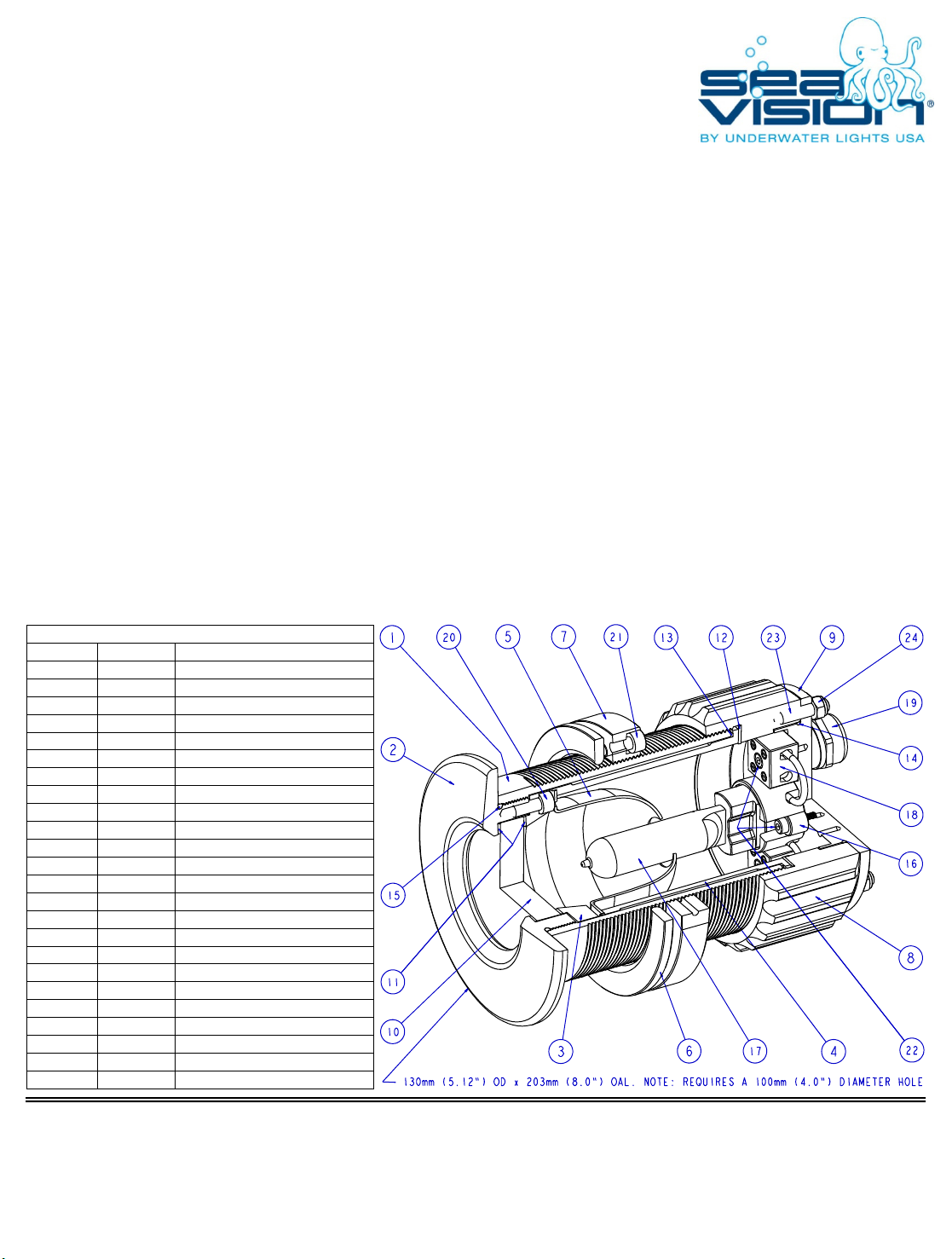
BALLOON PART DESCRIPTION
1 10001 MAIN BODY / COFFERDAM
2 10002 FRONT FLANGE
3 10003 GLASS RETAINING RING
4 10004 REFLECTOR TUBE
5 10005 REFLECTOR
6 10006 COMPRESSION RING
7 10007 LOCKING RING
8 10008 CONNECTING RING
9 10009 PROJECTOR LID
10 10010 GLASS
11 10011 GLASS GASKET
12 10012 CONNECTING RING GASKET
13 10013 REFLECTOR TUBE O-RING
14 10014 PROJECTOR LID O-RING
15 10015 FRONT FLANGE O-RING
16 10016 LAMP SOCKET
17 10034 LAMP, 150 WATT
18 10018 PORCELAIN TERMINAL BLOCK
19 10019 CABLE STRAIN RELIEF
20 10020 M6 x 1.0 x 14LG SST SHCS
21 10020 M6 x 1.0 x 14LG SST SHCS
22 10032 M4 x 0.7 x 16LG SST SHCS
23 10024 M6 x 1.0 x 25LG SST SET SCREW
24 10025 M6 x 1.0 SST HEX LOCKNUT
Installation:
To be installed by qualified personnel only at minimum 250-300mm (10-12”) below the light load water line using proper tools and materials. The
minimum hull thickness is 10mm (0.4”) and maximum (for sufficient light cooling) is 90mm (3.5”) with an access area of at least 75mm (3”) left
behind the light for lamp servicing and general ventilation.
After selecting a flat surface, cut a 100mm (4”) diameter hole through the vessel hull in the desired location. Caution! Check that no electrical
wiring, fuel lines, oil lines, water lines etc., pass near or through the intended hole location.
For light disassembly remove six nuts (24), remove Projector Lid (9), carefully disconnect ground wire, remove Connecting Ring (8), remove
LockingRing(7)andremoveCompressionRing(6)fromMainBody(1). Warning! Do not rotate Connecting Ring (8) while attached to
Projector Lid (9) or ground wire damage will occur! Carefully coat Main Body (1), Front Flange (2) and inner surface of hull hole with 3M
5200 Marine Adhesive or equivalent. Caution! Avoid placing excess adhesive on Main Body (1) threads. Note: Exposed inner hole surface must be
properly sealed before light installation to prevent potential water intrusion into the hull proper. Holding Front Flange (2), push Main Body (1)
through hull hole, slide Compression Ring (6) over Main Body (1) and then tighten Locking Ring (7) hand tight. Note: Ensure that the tips of all six
fasteners (21) are NOT touching Compression Ring (6). After the 3M 5200 Marine Adhesive is fully cured, tighten six fasteners (21) to 9 Nm (7
ft/lbs) using a 5mm allen wrench.
Upon making proper electrical connections (see ballast manual), reverse aforementioned light disassembly procedure and tighten six nuts (24) in a
criss-cross pattern to 2 Nm (1.5 ft/lbs). Note: Apply anti-seize compound to Connecting Ring (8) internal threads. Upon completing light
installation, it is highly recommended that Front Flange (2) be coated with antifouling paint. Also, hand tighten 4mm set screw located in Locking
Ring (7), then connect wire lead from 4mm screw provided on Locking Ring (7) to the vessels grounding and cathodic protection system.
Serviceable Parts:
For Lamp replacement remove six nuts (24), remove Projector Lid (9), carefully pull Lamp (17) out of Lamp Socket (16), push new Lamp (17) into
Lamp Socket (16), install Projector Lid (9) and tighten six nuts (24) in a criss-cross pattern to 2 Nm (1.5 ft/lbs). Caution! Ensure that the new lamp
is clean and free of dust, dirt, grease, oil, water and finger prints.
For glass replacement remove six nuts (24), remove Projector Lid (9), carefully disconnect ground wire, remove Connecting Ring (8), remove
Reflector Tube (4), remove Glass Retaining Ring (3), remove six fasteners (20) and remove Glass Gasket (11). Upon thoroughly cleaning all
surfaces, reverse said procedure to assemble and tighten six nuts (24) in a criss-cross pattern to 2 Nm (1.5 ft/lbs). Note: Six fasteners (20) are
tightened in a criss-cross pattern to 9 Nm (7 ft/lbs) using a 5mm allen wrench.
SV10 Light 120VAC/150W
240VAC/150W
Underwater Lights Europe Sarl
16, rue Rouaze
06400 Cannes, France
Phone: 33-(0)-4-97-21-02-96
Fax: 33-(0)-4-97-21-10-96
Internet: www.seavision.com
Underwater Lights USA, LLC
3406 SW 26th Terrace, C-6/7
Fort Lauderdale, FL 33312USA
Phone: 1-954-760-4447
Fax: 1-954-525-3261
Internet: www.seavision.com
Email: sales@seavision.com DOC:101205-14 Email: [email protected]

Introduction:
Congratulations on the purchase of your new thru hull light ballast box. Underwater Lights®USA, LLC takes pride in providing well
designed, high quality and thoroughly tested lights that allow you to “enhance your boating experience”. These lights can be
installed in your vessel for aesthetics, to attract fish, for security and safety.
Features Include:
Latest microprocessor control technology to guarantee high levels of performance.
Flicker free lighting and enhanced lamp life is provided by a square wave lamp current waveform.
Constant power feature ensures excellent color maintenance throughout the extended life of the lamp.
Transient, short circuit, thermal, open circuit, no lamp, hot lamp shutdown, retry and ignition failure protections.
Electrical wiring terminal block with VAC input fuse protection.
General Safety Information:
This ballast box is specifically designed for use with matching Underwater Lights USA, LLC brand lights only.
Always ensure that VAC power is disconnected and locked out before performing ballast box installation and/or service.
The ballast box should be opened and visually inspected every six months.
Ballast box electrical cabling should be visually inspected for proper operating condition every six months.
Technical Specifications:
Box Dimensions = 220mm (8.66”) long x 120mm (4.72”) wide x 91mm (3.58”) deep - 1.9 kilograms (4.2 pounds)
Box Construction = Molded gray, glass reinforced polyester with integral rubber (EDPM) gasket, IP66/NEMA 4X rated
OR
Box Dimensions = 221mm (8.70”) long x 121mm (4.76”) wide x 80mm (3.15”) deep - 2.1 kilograms (4.7 pounds)
Box Construction = Gray powder coated diecast aluminum alloy with integral silicone rubber gasket, IP66/NEMA 4X rated
Ballast = 120 VAC, 50/60 Hz, 1.38 Ampere input - 150 Watt output - Minimum operating temperature -30°C (-22°F)
OR
Ballast = 240 VAC, 50/60 Hz, 0.69 Ampere input - 150 Watt output - Minimum operating temperature -30°C (-22°F)
Cable to Ballast Box = Marine grade electrical cable, 14/3 stranded copper wire, with as short a length as possible
Cable from Ballast Box to Light = High temperature silicone cable, 16/3 shielded copper wire, 15 meters (50 feet) max length
Terminal block fuse = Fast blow 10 Amp cylindrical, 6.3mm diameter x 25mm or 32mm long (0.25” diameter x 1.0” or 1.25” long)
Troubleshooting:
Pleased contact our technical support staff in Florida at 1-954-760-4447, Monday to Friday from 8:00 am to 5:00 pm EST.
Warranty:
Underwater Lights®USA, LLC warrants this ballast box to be free from defects in workmanship and materials for a period of two
years from the date of original purchase. Further, misuse, abuse, improper installation, neglect, improper shipping, damage caused
by disasters such as fire, flood and lightning, unauthorized repair or modifications will void said warranty. Should your ballast box
prove defective during the warranty period, promptly contact Underwater Lights®USA, LLC for an RMA number and then return the
ballast box freight prepaid with the RMA number clearly marked on the outside of the shipping container.
SV18 Ballast Box
120VAC/150W
240VAC/150W
Underwater Lights Europe Sarl
16, rue Rouaze
06400 Cannes, France
Phone: 33-(0)-4-97-21-02-96
Fax: 33-(0)-4-97-21-10-96
Internet: www.seavision.com
Underwater Lights USA, LLC
3406 SW 26th Terrace, C-6/7
Fort Lauderdale, FL 33312USA
Phone: 1-954-760-4447
Fax: 1-954-525-3261 Internet:
www.seavision.com Email:
sales@seavision.com DOC:092005-11 Email: [email protected]

Installation:
Select a location that affords good access to the ballast box. Preferablytheballastboxshouldbeplacedinacool,dryandwell
ventilated area. Attach the ballast box to a fixed wall or similar secure structure using appropriate M6 fasteners. Note: Whereas,
the ballast box can be placed in any orientation, it is recommended that the cable strain relief connectors face down.
Using marine grade cable, run a VAC input line into the ballast box and secure by way of one cable strain relief connector.
Using a high temperature 18/3 shielded silicone cable, run a line from the ballast box to the underwater light and secure each end
by way of a strain relief connector. Caution! Avoid making tight bends and/or passing cable over sharp edges/surfaces.
Connect cable leads at both the ballast box and underwater light as shown in the wiring diagram below.
Serviceable Parts:
Upon opening the ballast box by unscrewing four captive lid fasteners, replacement of the HID ballast and/or terminal block with
fuse is accomplished by removal and replacement of three phillips pan head screws and associated wiring. Further, a 10 Amp fuse
located in the fused terminal block may be pulled out and replaced as required. Caution! Ensure that VAC power is disconnected
andlockedoutbeforeservicingballastbox.
SV18 Ballast Box
120VAC/150W
240VAC/150W
Underwater Lights Europe Sarl
16, rue Rouaze
06400 Cannes, France
Phone: 33-(0)-4-97-21-02-96
Fax: 33-(0)-4-97-21-10-96
Internet: www.seavision.com
Underwater Lights USA, LLC
3406 SW 26th Terrace, C-6/7
Fort Lauderdale, FL 33312USA
Phone: 1-954-760-4447
Fax: 1-954-525-3261 Internet:
www.seavision.com Email:
sales@seavision.com DOC:092005-11 Email: [email protected]
FAST BLOW FUSE18013
M3.5 x 0.6 x 12LG PPHS18011
M4 x 0.7 x 8LG SST PPHS18010
M6 x 1.0 x 8LG SST PPHS18009
FUSED TERMINAL BLOCK18008
240VAC BALLAST, MODEL 11A16B18007
120VAC BALLAST, MODEL 10A16B18006
BLANKING PLUG18005
CABLE STRAIN RELIEF18004
TERMINAL BLOCK MOUNT18003
MOUNTING PLATE18002
ENCLOSURE, PLASTIC
ENCLOSURE, ALUMINUM
18001
18020
DESCRIPTIONPART
120VAC BALLAST, MODEL 10A19B18017
240VAC BALLAST, MODEL 11A19B18018
16/3 HIGH TEMP SHIELDED SILICONE ELEC CABLE
18019
MODELS 10A16B & 10A19B, 120VAC/150W
MODELS 11A16B & 11A19B, 240VAC/150W
8-18 x 6LG THREAD FORMING SST PPHS18021
GROUND WIRE ASSEMBLY18022

English:
All drawings of general management, design detail and invention are the property of Underwater Lights USA, LLC and
may be used solely for work contracted or by express written permission of Underwater Lights USA, LLC.This applies
to first hand use and material on loan to others.Any infringement may be liable to penalty and/or compensation
without regard to the question of guilt. All drawings are subject to detail development during the course of
construction, and all rights of reproduction are reserved.Any information provided by Underwater Lights USA, LLC in
either hard copy or electronic format may be subject to change/s without prior purchaser, customer or end user
notice.
French:
Tous les dessins, détails généraux,de conception et d’invention sont la propriété de Underwater Lights USA, LLC et ne
peuvent être utilisés que pour des travaux sous contrat ou avec l’autorisation écrite expresse de Underwater Lights
USA, LLC.Ceci s'applique à la fois à la première utilisation et au matériel emprunté ou visualisé par des tiers.Toute
infraction peut faire l’objet de sanctions et /ou d’une indemnisation sans qu'il soit nécessaire d'établir la preuve de
culpabilité. Tous les dessins font l’objet de développements détaillés pendant la construction et tous les droits de
reproduction sont réservés.Les informations fournies par Underwater Lights USA, LLC, en version papier ou
électronique,peuvent être sujettes à modification(s) sans notification préalable à l'acheteur,au client ou à l'utilisateur
final.
Italian:
Tutti idisegni,generali,dettagli di progettazione edi invenzione sono di proprietà della Underwater Lights USA, LLC e
possono essere utilizzati esclusivamente per il lavoro contratto omediante espressa autorizzazione scritta della
Underwater Lights USA, LLC. Ciò vale sia per la prima utilizzazione sia per il materiale in prestito o visione a terzi.
Qualsiasi infrazione può essere soggetta asanzioni e/o indennizzi senza considerare la questione del senso di colpa.
Tutti i disegni sono soggetti a sviluppo dettagliato durante la costruzione esono riservati tutti i diritti di riproduzione.
Le informazioni fornite dalla Underwater Lights USA, LLC, in copia cartacea o elettronica, possono essere soggette a
modifica/modifiche senza preavviso all'acquirente, al cliente o all'utente finale.
Spanish:
Todos los dibujos, detalles de diseño y creación son propiedad de Underwater Lights USA, LLC ypueden ser utilizados
únicamente para trabajos relacionados o a través de autorización escrita de Underwater Lights USA, LLC. Esto aplica a
utilizarlos de primera mano o a material prestado aotros.Cualquier violación de estos términos puede ser penalizada
y/o una compensación puede ser requerida sin cuestionar la culpabilidad. Todos los dibujos están sujetos a ser
desarrollados en detalle durante el transcurso de la construcción ytodos los derechos de reproducción son reservados.
Toda la información proporcionada por Underwater Lights USA, LLC tanto en forma impresa como digital está sujeta a
cambios en cualquier momento sin notificarle al comprador, cliente o usuario final.
IMPORTANT NOTICE!
Underwater Lights Europe Sarl
16, rue Rouaze
06400 Cannes, France
Phone: 33-(0)-4-97-21-02-96
Fax: 33-(0)-4-97-21-10-96
Internet: www.seavision.com
Underwater Lights USA, LLC
3406 SW 26th Terrace, C-6/7
Fort Lauderdale, FL33312USA
Phone: 1-954-760-4447
Fax: 1-954-525-3261 Internet:
www.seavision.com Email:
This manual suits for next models
2
Table of contents
Other Underwater Lights USA Underwater Lighting manuals

Underwater Lights USA
Underwater Lights USA Sea Vision SV20 LED User manual

Underwater Lights USA
Underwater Lights USA Sea Vision SV14 User manual

Underwater Lights USA
Underwater Lights USA Sea Vision SV10 LED User manual

Underwater Lights USA
Underwater Lights USA sea vision SV60 User manual

Underwater Lights USA
Underwater Lights USA Sea Vision SV16 User manual

Underwater Lights USA
Underwater Lights USA Sea Vision SV16 User manual

Underwater Lights USA
Underwater Lights USA sea vision SV18 User manual

Underwater Lights USA
Underwater Lights USA Sea Vision SV14 LED User manual