Uni-ram UG7500 Series User manual

REV 2018-01
OPERATING MANUAL
AUTOMATIC SPRAY GUN CLEANERS
UG7500 SERIES
PATENTS
U.S.A. 4,785,836 CANADA 1293909
U.S.A. 5,213,117 ENGLAND EP 0300248 (UK)
EUROPE 0300248 ITALY 69760/BE/92
SWEDEN 0300248 GERMANY DE 38 75 412
FRANCE 8110528.0 JAPAN 1-302098
UNI-RAM CORPORATION • ONTARIO • CANADA

MANUAL - SPRAY GUN CLEANERS - UG7500 SERIES REVISION 2011-05
2
CONTENTS
INTRODUCTION . . . . . . . . . . . . . . . . . . . . . . . . . . . . . . . . . . . . . . . . . . . . . . . . . . . . . . . . . . . . . . 3
CAUTIONS AND WARNINGS . . . . . . . . . . . . . . . . . . . . . . . . . . . . . . . . . . . . . . . . . . . . . . . . . . . . 3
FEATURES AND OPTION COMPARISON . . . . . . . . . . . . . . . . . . . . . . . . . . . . . . . . . . . . . . . . . . 3
STRUCTURE OF SPRAY GUN CLEANERS. . . . . . . . . . . . . . . . . . . . . . . . . . . . . . . . . . . . . . . . . 4
SETUP
INSPECTION . . . . . . . . . . . . . . . . . . . . . . . . . . . . . . . . . . . . . . . . . . . . . . . . . . . . . . . . . . 5
LOCATION . . . . . . . . . . . . . . . . . . . . . . . . . . . . . . . . . . . . . . . . . . . . . . . . . . . . . . . . . . . . 5
LEVELING, VENT AND AIR SUPPLY. . . . . . . . . . . . . . . . . . . . . . . . . . . . . . . . . . . . . . . . 5
SOLVENT SELECTION . . . . . . . . . . . . . . . . . . . . . . . . . . . . . . . . . . . . . . . . . . . . . . . . . . 5
SOLVENT PAIL SETUP . . . . . . . . . . . . . . . . . . . . . . . . . . . . . . . . . . . . . . . . . . . . . . . . . . 6
GROUND WIRE INSTALLATION . . . . . . . . . . . . . . . . . . . . . . . . . . . . . . . . . . . . . . . . . . . 7
OPERATION
PRE - CLEAN . . . . . . . . . . . . . . . . . . . . . . . . . . . . . . . . . . . . . . . . . . . . . . . . . . . . . . . . . . 7
CLEANING SPRAY GUNS AND CUPS . . . . . . . . . . . . . . . . . . . . . . . . . . . . . . . . . . . . .7-8
USING THE MANUAL WASH and RINSE . . . . . . . . . . . . . . . . . . . . . . . . . . . . . . . . . . . . 8
SPRAY GUN TESTING. . . . . . . . . . . . . . . . . . . . . . . . . . . . . . . . . . . . . . . . . . . . . . . . . . . 8
HOSE CLEANING (FACTORY OPTION). . . . . . . . . . . . . . . . . . . . . . . . . . . . . . . . . . . . . 8
AFTER CLEANING. . . . . . . . . . . . . . . . . . . . . . . . . . . . . . . . . . . . . . . . . . . . . . . . . . . . . . 8
CONNECTING TO A SOLVENT RECYCLER. . . . . . . . . . . . . . . . . . . . . . . . . . . . . . . . . . 8
DAILY MAINTENANCE
FILTER PADS AND SCREEN. . . . . . . . . . . . . . . . . . . . . . . . . . . . . . . . . . . . . . . . . . . . . . 9
REPLACING SOLVENT . . . . . . . . . . . . . . . . . . . . . . . . . . . . . . . . . . . . . . . . . . . . . . . . . . 9
TROUBLESHOOTING CHART . . . . . . . . . . . . . . . . . . . . . . . . . . . . . . . . . . . . . . . . . . . . . . . .10-11
TROUBLESHOOTING PROCEDURES. . . . . . . . . . . . . . . . . . . . . . . . . . . . . . . . . . . . . . . . . . . . 12
FLOW DIAGRAMS. . . . . . . . . . . . . . . . . . . . . . . . . . . . . . . . . . . . . . . . . . . . . . . . . . . . . . . . 13 & 16
REPLACEMENT PARTS . . . . . . . . . . . . . . . . . . . . . . . . . . . . . . . . . . . . . . . . . . . . . . . . . . . . .14-15
ACCESSORIES, OPTIONS AND CONSUMABLES . . . . . . . . . . . . . . . . . . . . . . . . . . . . . . . . . . 17
WARRANTY
EXTENDED WARRANTIES For North American Customers. . . . . . . . . . . . . . . . . . . . . 17
FULL PRODUCT WARRANTY. . . . . . . . . . . . . . . . . . . . . . . . . . . . . . . . . . . . . . . . . . . . 18

3
MANUAL - SPRAY GUN CLEANERS - UG7500 SERIES REVISION 2011-05
INTRODUCTION
Uni-ram holds many patents on designs used in its innovative products. Every machine is rigorously
tested for compliance with stringent Quality Assurance standards. Follow the directions in this manual
under Setup, Operation and Maintenance in order to operate this machine safely and effectively. Not
following these instruction can lead to malfunction or damage to the machine. Follow directions under
the section below, Cautions and Warnings, and on labels attached to the machine. Ensure that the
manual is readily available for the operator at all times. If you have any questions about the operation
of this machine, call your distributor or a Uni-Ram Service Engineer.
CAUTIONS AND WARNINGS
• Always disconnect this machine from power sources before performing maintenance
• Do not smoke or use near open flames, sparks or heat.
• Ground pails and cabinet using supplied grounding wires
Basic UG7500 Model has the following features
• Auto Wash, Clean rinse and air purge
• Manual Wash - Brush and Rinse - Flexible Spigot
• Three Diaphragm Pumps and Rinse Pumps
• Hand free - Foot pedal Operation
• Manual and Automatic Fume exraction
• Clean 2 Guns and 2 Cups (2 Nozzles and 14 Jets)
• One Pail
• Hood - Stainless Steel
North America:
Uni-ram Technical Service
1-800-417- 9133
Other Continents:
Contact Your Supplier

MANUAL - SPRAY GUN CLEANERS - UG7500 SERIES REVISION 2011-05
4
VAPOUR FILTER
UG7500LE
AIR SUPPLY OUTLET
TEST - UG7500LEPRESSURE GAUGE
SPRAY GUN TESTING
UG7500LE AIR ON/OFF, SPRAY GUN
TESTING - UG7500LE
AIR RINSE
(on “NG” Model, this pedal
operates the Manual
Rinse Spigot)
CLEAN RINSE
(except “NG” Model)
MANUAL RINSE
SPIGOT (on “NG”
Model, use left pedal)
MANUAL WASH
BRUSH
AUTOMATIC
WASH TIMER
(except “NG” Model)
AIR VENT
ON/OFF
HOOD DOOR
FLOW-THROUGH
BRUSH FOR
MANUAL WASH
SPIGOT FOR
MANUAL WASH
WASH SINK WITH
WASH SCREEN
TANK LID
(except “NG” model
WASH TANK
STRUCTURE AND KEY COMPONENTS
(For “NG” model, see page 16)
BRUSH FLOW CONTROL
NOZZLE FLOW CONTROL

5
MANUAL - SPRAY GUN CLEANERS - UG7500 SERIES REVISION 2011-05
SETUP
INSPECTION
• Inspect the shipping carton for signs of damage. It is your responsibility to report damage to the
transport company. Uni-ram Corporation does not accept responsibility for shipping damage
once the machine has left our warehouse. Keep the packaging materials until you are sure the
machine has not been damaged during shipping.
• Remove the machine from the carton by opening the bottom flaps and sliding the carton up over
the machine.
• Make sure the bag of accessories contains the following:
• Manual
• Kit - Plug, Guns W.Trigger Lock Springs, 2 pieces (Part No. 140-2340)
• Nozzle Adapters, 1 each of 2 kinds (Part No. 110-430 and 110-430PPS)
• Hood Door Support (Part No. 780-3723)
• Remove the protective covers on all the oulets.
If any items are missing, contact your supplier.
LOCATION
Position in a well-ventilated area away from sparks, heat and open flames.
LEVELING, VENT AND AIR SUPPLY
• Level the machine using the adjustable legs.
• Attach a vent hose (not supplied) to the vent outlet on top of the
machine. The duct system must not be under continuous vacuum.
• Attach an air supply adapter (not supplied) to Air Inlet Fitting (see
right).
The air supply pressure must be at least 85 PSI and
the air must be free from contaminants such as water, dust, rust, tar,
grease etc.
To prevent damage to the Diaphragm Pump an internal Air Pressure
Regulator has been installed to limit the air pressure to precisely 85
PSI. Do not install a second air pressure regulator or use a pressure
set below 85 PSI.

MANUAL - SPRAY GUN CLEANERS - UG7500 SERIES REVISION 2011-05
6
• Inside the cabinet you will see two pipes strapped together, the Suction Pipe and the Rinse
Pump. Cut the strap holding them together. Do not cut the other straps holding the black and
blue tubes.
• Disconnect the Suction Pipe from the Drain Valve by pushing the gray button and bring both
pipes outside of the cabinet.
• Insert the Rinse Pump into the full pail on the right and the Suction Pipe into the pail with 3 gal
on the left. Insert the Manual Wash Suction Tube into the lid of the left (wash) pail, as shown.
Insert the Manual Rinse Suction Tube through the lid of the right (rinse) pail, as shown.
• Move the pails into the cabinet and re-connect the
Suction Pipe of the left pail to the Drain Valve.
GROUND WIRE INSTALLATION
• Three ground wires are provided to discharge static
electricity. To work properly, all three must be installed
correctly. Connect the two ground wires inside the cabi-
net to Suction Pipe and to Rinse Pump and the wire on
the outside back of the cabinet to an external grounded
object.
OPERATION
PRE - CLEAN
• Disconnect the spray gun from the air hose. Pour paint from the cup (when present) into a 5
gallon pail (not supplied).
Drain Valve
PAIL NO.2
WASH SOLVENT
780-8110P
MANUAL WASH
SUCTION TUBE
SUCTION PIPE
ASSEMBLY
PAIL NO. 1
CLEAN SOLVENT
780-8120P
MANUAL RINSE
SUCTION TUBE
RINSE PUMP
ASSEMBLY
GROUND WIRE
GROUND WIRE
TRANSFER
HOSE OUT
TRANSFER
HOSE IN
Note: The “NG” model has a Stainless Steel Pail Set, see page 16.

7
MANUAL - SPRAY GUN CLEANERS - UG7500 SERIES REVISION 2011-05
SOLVENT SELECTION
The adhesion quality of automotive paint has dramatically improved in recent years. The choice of sol-
vent is critical. Use only good quality solvent that is formulated for your paint and intended for use with
automatic spray guns cleaners.
SOLVENT PAIL SETUP
• Remove the door of the base cabinet
• Move the Drain Valve handle to the "open" (vertical) position if it is not already there. See pic-
ture.
• Two 5-Gal (19 L) pails of solvent are required, one full and one containing 3 Gal. Place the pails
in front of the machine, full pail on the right and the other pail on the left.

MANUAL - SPRAY GUN CLEANERS - UG7500 SERIES REVISION 2011-05
8
• Rinse cup with solvent and pour into the same
5 gallon pail for later disposal or recycling.
CLEANING SPRAY GUNS AND CUPS
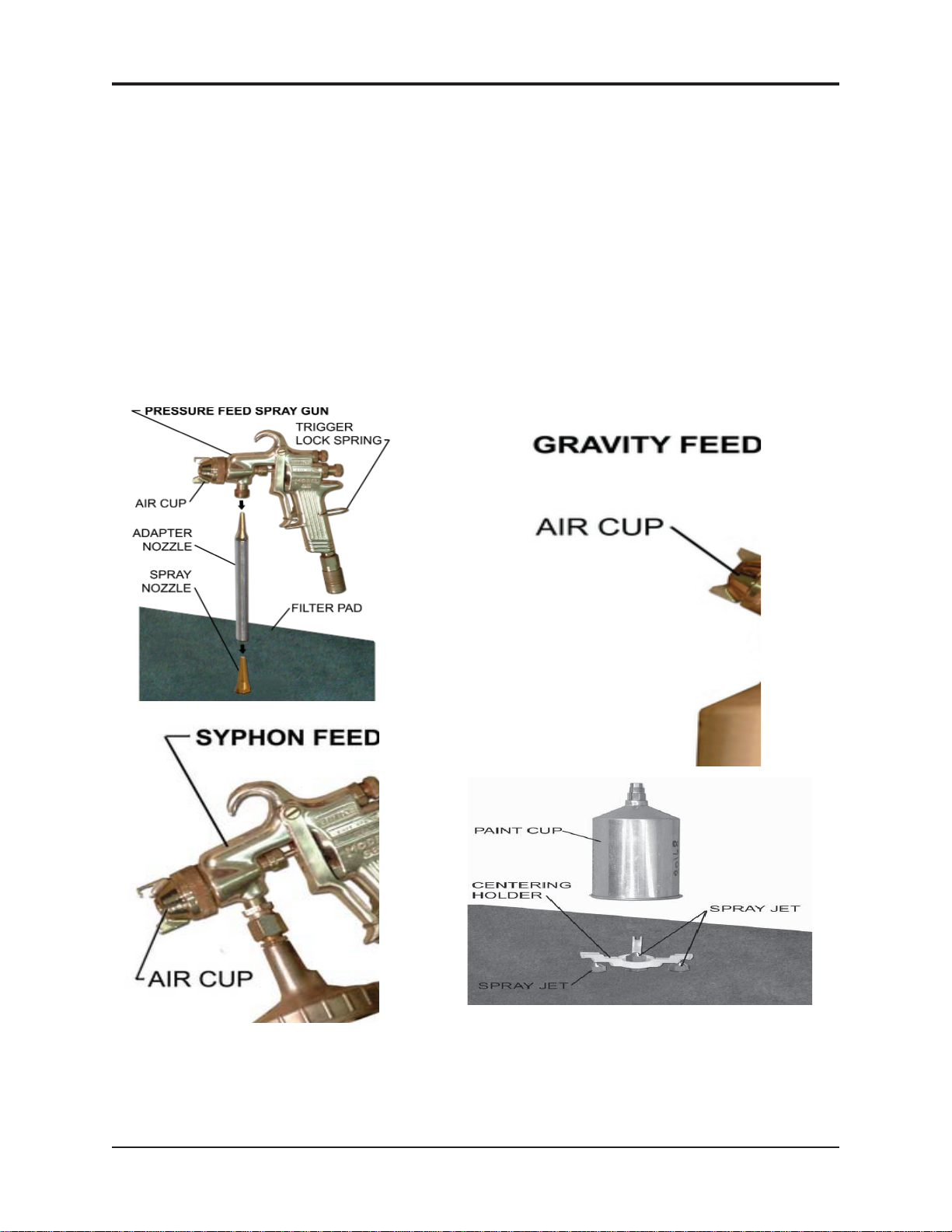
• Loosen the air cap of the spray gun two full turns.
• Lock the trigger in the open position with the Trigger Lock Spring.
• To prevent liquid from entering the air passgae during automatic clean-
ing, insert the white plastic Air Passage Plug into the Spray Gun's air
inlet. If the air inlet has a male threaded connector instead of a quick
connect use the knurled nut attached to the Trigger Clamp (included).
SELECTION OF NOZZLE EXTENSION
780-3530 INSTALLED. HOLES PROVIDE SOLVENT TO CEAN DISPOSABLE CUP ADAPTOR.
CANNOT BE USED FOR CONVENTIONAL SYSTEMS.
110-43099S HOLES PROVIDE SOLVENT TO CLEAN DISPOSABLE CUP ADAPTOR. MAY ALSO
BE USED FOR CONVENTIONAL SYSTEMS WITH LARGER OPENINGS IN NECK OF
CUP.
110-430 FOR CONVENTIONAL SYSTEMS ONLY WITH SMALLER OPENINGS IN NECK OF
CUP.
CLEANING SPRAY GUNS AND CUPS (except for “NG” model)
• Place spray guns facing corner jets. Placement depends on type of spray gun. See pictures.
Place cups onto the low spray jets and cup holders.
• Close the lid and turn the “Auto Wash Timer” knob clockwise to start cleaning. The cleaning takes
about 60seconds
• Push and hold the "Air Rinse" button for about 3 second to air-rinse the guns.
• Push and hold the "Clean Rinse" button for about 5 seconds to rinse guns with clean solvent. This
will send a pre-set amount of clean solvent (100 cc) through the jets. Wait 30 seconds for the
Rinse Pump to fully recharge before repeating.
The s
olvent flow per clean-rinse cycle is limited to 100 cc to minimize consumption. This quantity
is usually sufficient to clean the inside pasages of the spray guns.
USING THE MANUAL WASH and RINSE
Manual Wash Brush (used solvent)
• Step on the manual wash pedal. A dedicated pump delivers wash (used) solvent through the
brush.
Manual Rinse Spigot (clean solvent)
• Step on the manual rinse pedal. Clean solvent is delivered through the spigot.
SPRAY GUN TESTING - LE model only (see picture on page 4 or 14)
• Connect the Spray Gun to the Air Supply Outlet and turn on the Air using the Air On/Off lever.
• Check the air pressure on the Pressure Gauge. Using the Pressure Regulator (inside the cabinet
on the right), adjust the pressure according to the requirements of the Gun (pre-set value is 15-25
PSI).
• Test the Gun and turn off the Air when finished.

9
MANUAL - SPRAY GUN CLEANERS - UG7500 SERIES REVISION 2011-05
HOSE CLEANING - FACTORY OPTION (except “NG” model))
• This feature can be used to clean a paint feeder hose up to 100 feet (30 m) long. Connect the
hose to the two fittings, one on the lid and one on the right side. Rotate the "Mode Selector" han-
dle to the horizontal position and turn the Timer knob clockwise to start the automatic cleaning
cycle.
AFTER CLEANING
• Remove the guns and cups from the tank and wipe them dry. Do not store spray guns in the tank.
CONNECTING TO A SOLVENT RECYCLER
• On the back of the machine, connect the Transfer Hoses to the Solvent-In and Solvent-Out con-
nectors.
DAILY MAINTENANCE
FILTER PADS AND SCREEN
• Inspect the filter pad in the bottom of the cleaning tank and, if there is a build up of paint debris,
clean the pad by removing it from the tank and washing away the paint debris.
REPLACING SOLVENT
• Disconnect the Suction Pipe from the Drain Valve and remove the pipe from the pail. Move the
pail out of the cabinet and recycle or dispose of the dirty wash solvent. .
• Place a new, full-pail of clean solvent in front of the cabinet.
• Move the pail into the cabinet and re-connect the Suction Pipe to the Drain Valve.

MANUAL - SPRAY GUN CLEANERS - UG7500 SERIES REVISION 2011-05
10
…continued next page
SYMPTOM REASON CORRECTIVE ACTION
• Drain valve closed •
Open drain valve (put in verticle
position), if not already open
Check wash solvent level. Add
solvent if less than 1/2 full.
• Solvent level too low • Check wash solvent level. Add
solvent if less than 1/2 full
•Paint debris in pump or
blockage in solvent line •Follow Procedure 1, "Blocked
Fluid Passage in Diaphragm
Pump"
WASH SOLVENTDOES NOT
FLOW AND PUMP MAKES A
HISSING NOISE •Water in air line causes
pump to stall •Follow Procedure 2, "Blockage in
Air Passage in Diaphragm Pump"
• Pump leaks • Replace pump
• Blockage in air passage • Follow Procedure 3, "Blocked
Passage in Air Line".
PUMP DOES NOTSTOP
UNLESS TIMER IS TURNED BY
HAND OR AIR IS SHUT OFF • Defective Timer • Replace timer
TIMER KNOB SPINS BACK
WHEN TURNED • Defective Timer • Replace timer
INSIDE WALL OF TANK IS
COATED WITH PAINT EVEN
THOUGH OPERATOR
MAINTAINS TANK
•Solvent lacks cleaning
strength •
Replace solvent with solvent that
is formulated for type of paint used
and for use with automatic spray
gun cleaning
GUNS NOT CLEAN, PUMP
WORKING, SOLVENT FLOW
NORMAL •Trigger not locked in open
position • Use Trigger Lock Spring
•Spray gun is not properly
installed onto nozzle • Re-install with proper adapter
• Incompatible solvent •
Replace incompatible solvent with
solvent formulated for the type of
paint used and for Automatic
Spray Gun Cleaners.
• Low pressure in air supply • Increase air pressure to a
minimum of 85 PSI
• Plugged jets • Remove and clean by blowing air
through the jets. If not successful,
replace.
GUNS NOT CLEAN, WASH
SOLVENT IS MILKY WHITE •Wash solvent is
contaminated with water • Replace or recycle wash solvent
GUNS NOT CLEAN, WASH
SOLVENT IS MILKY WHITE
WASH SOLVENTDOES NOT
FLOW AND PUMP MAKES A
PUMPING NOISE
WASH SOLVENTDOES NOT
FLOW AND PUMP DOES NOT
MAKE A NOISE
TROUBLESHOOTING CHART - UG7500 SERIES

11
MANUAL - SPRAY GUN CLEANERS - UG7500 SERIES REVISION 2011-05
SYMPTOM REASON CORRECTIVE ACTION
After Each Step Below, start the Timer. If solvent doesnot flow, carry out the next step.
GUNS NOT CLEAN, PUMP
WORKING, SOLVENTFLOW
NORMAL •Trigger not locked in open
position • Use Trigger Lock Spring
•Spray gun is not properly
installed onto nozzle • Re-install with proper adapter
• Incompatible solvent •
Replace incompatible solvent
with solvent formulated for the
type of paint used and for
Automatic Spray Gun
Cleaners.
• Low pressure in air supply • Increase air pressure to a
minimum of 85 PSI
• Plugged jets • Remove and clean by blowing
air through the jets. If not
successful, replace.
GUNS NOT CLEAN, WASH
SOLVENT IS MILKY WHITE •Wash solvent is contaminated
with water •Replace or recycle wash
solvent
TROUBLESHOOTING CHART - UG7500 SERIES … continued
GUNS NOT CLEAN, WASH
SOLVENT IS MILKY WHITE
CLEANING PROBLEMS

MANUAL - SPRAY GUN CLEANERS - UG7500 SERIES REVISION 2011-05
12
TROUBLESHOOTING PROCEDURES
PROCEDURE 1
Blocked Fluid Passage In Diaphagm Pump
If the pump sounds like it is working but liquid does not flow, clear the
fluid passage as follows:
• Remove suction tube from the pail and blow air at 85 PSI into the
INLET Sovent Hose (see diagram). Step on foot pedal. This
procedure may have to be repeated several times. If this pro-
cedure does not help, blow some water into the suction hose
using a spray gun, wait one minute and step on foot pedal.
This procedure may have to be repeated several times. If this
procedure does not work, the pump must be replaced.
If you need to replace the pump call your local dealer. The warran- ty
on the diaphragm pump is two years from date of purchase.
This procedure will also clear a blockage in the fluid line for the wash gun.
PROCEDURE 2
Blocked Air Passage In Diaphragm Pump
If there is a steady hissing sound and the pump is not cycling, the spool valve has stalled due to a
blocked air passage. Follow the procedure below to clear the blockage.
• Connect a blow gun to an 85 PSI source. Locate the
blue hose that extends from the air exhaust port of the dia-
phragm pump. Use a blow gun to blow air into the open end
of this hose. Turn timer. If the procedure is successful, the
pump will start working. The procedure may have to be
repeated several times. If this procedure does not work,
replace the pump.
• Cause: Contaminants in the air supply (water, oil, solid parti- cles
etc)
• Preventative Action: If necessary, install an Airline (Moisture)
Filter.
PROCEDURE 3
Blocked Passage in Air Line
The components in the air line are the diaphragm pump, air valve, foot pedal, 3-way ball valve and regu-
lator. See the Flow Diagram and the section: Replacement Parts.
To troubleshoot a component:
1) Disconnect the air line to the component using the quick disconnect.
2) Step on foot pedal and check for presence of positive air pressure in the air line. If there is ample
positive air pressure, replace the component.
If air pressure is absent, there is a faulty component upstream. Reconnect the air line and check the
operation of the next component upstream by following steps 1 and 2 above.

13
MANUAL - SPRAY GUN CLEANERS - UG7500 SERIES REVISION 2011-05
FLOW DIAGRAM(S)
Use the diagram(s) to trace the flow of compressed air and solvent (see page 17 for
the “NG” model).

MANUAL - SPRAY GUN CLEANERS - UG7500 SERIES REVISION 2011-05
14
115-200/K, Timer Kit
Cleaning Tank
144-390, Flow-
Through Brush
KIT-SRP, Spigot Kit
10-235F, Air Vent
On/Off Lever
Pedal/Valve
Assembly:
780-4300
Valve Only:
115-400BF
Wash Sink
REPLACEMENT PARTS UG7500 SERIES
(see page 16 for the “NG” model)
780-520, Vent
Tube
36-110J, Air Jet
(not shown)
Diaphragm
Pump,
UDP4TA
Adjustable Foot,
110-530L
Hood
Hood Door
FILTER, 780-3042
FRAME, 780-3050
UG7500LE
140-230A, Kit - Air Barrier
Kit 2 Pail Set.
780-8000
(except “NG” model,
see page 16) CARD SUPPORT, 780-3047
S-HOOK, 780-3045

15
MANUAL - SPRAY GUN CLEANERS - UG7500 SERIES REVISION 2011-05
144-390, Flow-
Through Brush
KIT-SRP, Spigot Kit
Wash Sink with Screen
Only (no Cleaning tank)
REPLACEMENT PARTS UG7500NG

MANUAL - SPRAY GUN CLEANERS - UG7500 SERIES REVISION 2011-05
16
FLOW DIAGRAM - UG7500NG ONLY

17
MANUAL - SPRAY GUN CLEANERS - UG7500 SERIES REVISION 2011-05
ACCESSORIES, OPTIONS AND CONSUMABLES
EXTENDED WARRANTIES For North American Customers
An extended warranty may be purchased within 3 months from the date of purchase.
There are two types of warranty:
1) parts
2) parts and labour
The warranty period is 2, 3 or 4 years.
If you would like to purchase an extended warranty call Uni-ram at:
Canada 1-800-417-9133
USA 1-800-735-4331
Model Part No. Description
Non “NG” 110-430 Nozzle Adapter, Conventional Systems Only
Non “NG” 110-430PPS Nozzle Adapter, All models, Push On
Non “NG” 780-3530 Nozzle Adapter, Disposable Cup Systems Only
Non “NG” 100-413F Paint Cap Holder
Non “NG” 115-200/K Mechanical Timer Assembly, 5 minutes
Non “NG” 140-340S Rotating Spray Jet Assembly
All 140-230 Air Passage Plug
All 100-835 Ground Wire for Gun Cleaner, 18G, Green, 4 FT
All 600-8901 Ground Wire for Pail
Non “NG” 780-8000 2-Pail Set required for connection to Solvent Recycler
Non “NG” FP6500-10 Flilter Pad, Pkg of 10
NG only FP7500NG-1 Filter Pad, Single
All UDP4TA Diaphragm Pump

MANUAL - SPRAY GUN CLEANERS - UG7500 SERIES REVISION 2011-05
18
Full Product Warranty
These Uni-ram products have been engineered and manufac-
tured to high performance standards. Each unit has been subjected to detailed factory testing
before shipment.
This product comes with a one-year full warranty from the date of purchase. Uni-ram Corporation
reserves the right to repair or replace the unit, free of charge, to the original purchaser if a part is
found to be defective in material or workmanship as determined by factory service personnel. The
items listed below under "Conditions of Warranty" as consumables are not covered.
Uni-ram reserves the right to direct the customer to ship the unit collect to the Uni-ram factory or to
an approved Service Center for repair using the Uni-ram Return Goods Procedure or to repair the
unit on-site. To prevent damage in transport, the purchaser must ship the unit in the original pack-
aging or use alternate adequate packaging. All units must be shipped clean and free of solvent.
Diaphragm Pump:
We are pleased to advise that the warranty on the diaphragm pump, the heart of the spray gun
cleaner, comes with a 2 year replacement warranty. If, in the unlikely event your diaphragm pump
fails during the first two years of service, call Uni-ram Service at 1-800-417-9133. We will send you
a new pump free of charge and arrange for the return of your original pump.
Conditions of Warranty:
As Uni-ram Corporation has no control over the working conditions or circumstances under which
the purchaser stores, handles or uses the product, Uni-ram makes no warranty or claim, either
expressed or implied with respect to this product's fitness for any purpose or the result to be
obtained from its use. This condition applies to the sale of all products and no representative or dis-
tributor of Uni-ram Corporation has the authority to waive or change these conditions.
This warranty applies only to the original purchaser and does not apply if the unit has been mis-
used, overloaded, neglected, altered or used for any purpose other than those specified in the
operating and installation instructions. Deterioration due to normal wear is not covered by this war-
ranty. Damage due to accident, transportation, fire, floods or acts of God is also not covered. Units
whose serial numbers have been altered or removed are not covered. The warranty is invalid if
unauthorized chemicals as noted in the manual or solvents with acid content are used in this unit.
Unauthorized attempts at self-repair or alterations by the owner also invalidate this warranty.
Interior or exterior finishes are not covered by this warranty.
Consumable Items are not covered by this warranty (eg: gaskets, screens, bags, filters, nozzles
and air jets).
This warranty replaces all other warranties expressed or implied by statute or otherwise.
To make a claim, call Uni-ram Service at 1-800-417-9133 and quote the serial number of the
unit.
Table of contents
Other Uni-ram Ultrasonic Jewelry Cleaner manuals

Uni-ram
Uni-ram UG2000DMV User manual

Uni-ram
Uni-ram UG7500W User manual

Uni-ram
Uni-ram UG2000DM Series User manual

Uni-ram
Uni-ram UG110 User manual

Uni-ram
Uni-ram UG5000W User manual

Uni-ram
Uni-ram UG4000D Manual

Uni-ram
Uni-ram UM80W User manual

Uni-ram
Uni-ram UG4000D User manual

Uni-ram
Uni-ram UG5000W Manual