manuals.online logo
Brands
  1. Home
  2. •
  3. Brands
  4. •
  5. Unipower
  6. •
  7. Power Distribution Unit
  8. •
  9. Unipower 1U Series User manual

Unipower 1U Series User manual

CORPORATION
Call North America: 954-346-2442 • [email protected]
Call Europe: +44(0) 1903 768200 • [email protected]
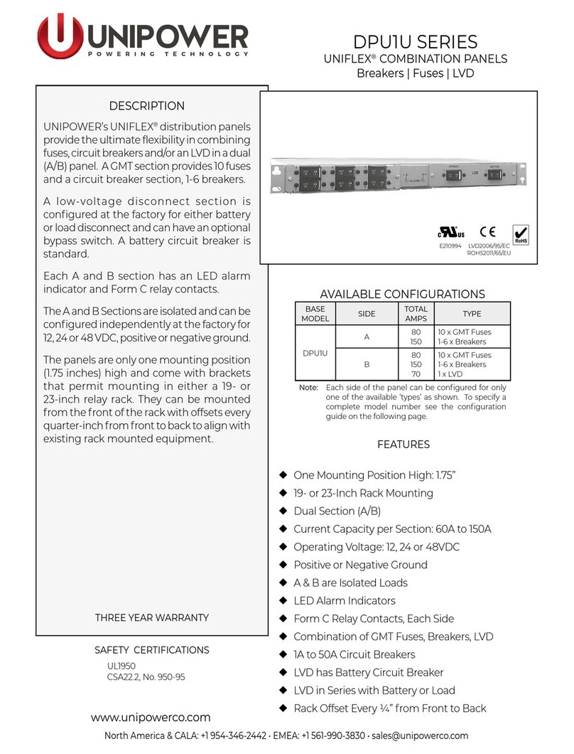
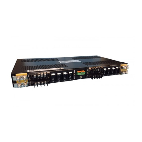
1U High Front End Power System Racks
FEATURES
75A Full Front Access 19-Inch Rack
TPCMR1U2
150A Front or Rear Access 19-Inch Rack
TPCMR1U3
nHolds Two TPCM or TPCP Models
nFits 12-Inch Max. ETSI Depth
nAC Line Cord Ready
nQuick Connect Input/Output
nIndividual AC Inputs
n12, 24 or 48VDC Output
nHot-Swap Operation
nUp to 1200W 1+1 Redundant
nUp to 2400W Non-Redundant
nOnly 1U High (1.72 inches)
n19- or 23-Inch Rack Mounting
nStackable for Expansion
n+5V, 250mA Standby Output
nI2C Serial Data Bus Option
nModule Present Signal
nControl & Monitoring Signals
NORTHAMERICA•3900 CoralRidgeDrive, CoralSprings,Florida 33065,USA• Tel:+1954-346-2442• Fax:+1954-340-7901 •[email protected]
EUROPE•ParklandBusinessCentre, ChartwellRoad, LancingBN158UE,England• Tel+44(0)1903768200• Fax+44(0)1903 764540•[email protected]
RACK ORDERING GUIDE
TPCMR1U3-E 3 ACFrontEntry 120A
(for TPCM DCRear Entry
OptionEonly) SignalsRearEntry
RACK
MODEL NO. MAX.NO.
MODULES CONNECTIONS
FEATURES
nHolds Three TPCM or TPCP Models
nCase Only 11.56 Inches (294 mm) Deep
nAC Line Cord Ready
nFront or Rear AC Entry (TPCM)
nIndividual AC Inputs
n12, 24 or 48VDC Output
nHot-Swap Operation
nUp to 2400W 2+1 Redundant
nUp to 3600W Non-Redundant
nOnly 1U High (1.72 mm)
n19- or 23-Inch Rack Mounting
nStackable for Expansion
n+5V, 250mA Standby Output
nI2C Serial Data Bus Option
nModule Present Signal
nControl & Monitoring Signals
nRear Output & Signal Connections
RACK ORDERING GUIDE
TPCMR1U2 2 AllFrontEntry 75A
RACK
MODEL NO. MAX.NO.
MODULES CONNECTIONS MAX.
CURRENT
MAX.
CURRENT
UL Listed
TPCM MODULE ORDERING GUIDE
600W 12VDC@50.0A 85-264VAC TPCM3000
700W 24VDC@29.2A 85-264VAC TPCM5000
800W 48VDC@16.7A 85-264VAC TPCM7000
480W [email protected] 85-264VAC TPCM3000E
525W [email protected] 85-264VAC TPCM5000E
600W [email protected] 85-264VAC TPCM7000E
MAX.
POWER OUTPUT VOLTAGE
AND CURRENT MODEL NO.
AC INPUT
RANGE
For a complete system, order a rack plus the required number of modules. For complete
specifications on the modules see PCM/TPCM or PCP/TPCP
PowerCassette
® datasheets. TWO-YEAR WARRANTY
TPCMR1U3 3 AllRearEntry 150A
For I2C version of rack, add suffix -Z to model number.
TPCP MODULE ORDERING GUIDE
800W 12VDC@66.7A 85-264VAC TPCP3000
1000W 24VDC@41.7A 85-264VAC TPCP5000
1200W 48VDC@25.0A 85-264VAC TPCP7000
MAX.
POWER OUTPUT VOLTAGE
AND CURRENT MODEL NO.
AC INPUT
RANGE
CORPORATION
North America: 954-346-2442 • [email protected]
Europe: +44(0) 1903 768200 • [email protected]
SPECIFICATIONS, 75-AMPERE FULL FRONT ACCESS 19-INCH RACK
1. Inputvoltage rangeis85-264VAC formaximum
powerin eitherredundant ornon-redundant
operation.
2. Theoutputs of thetwoPowerCassette modules are
connectedin parallelinthe rack.
3. Therack depthis11.56 inches(294mm).
4. Module A is on the left and module B on the right as
seenfromthe front of the rack.ACinputconnector
J1 goes to module A and J2 to module B.
5. Forfurther details onthecontrol signals on J3see
the PowerCassette PCM/TPCM or PCP/TPCP
datasheet or operatingmanuals.
6. For details on I2C data (J3 pins 9 and 13) see PCM/
TPCMoperatingmanual or contact factory.
7. TheModule Presentoutputs(J3 pins 20and21)
aregrounded (to -Sense)when the moduleis
pluggedin and openwhen the moduleis out.
ALL DIMENSIONS IN INCHES (mm). All specifications subject to change without notice.
FUNCTION
AC Power Fail - A
DC Power Good - A*
AC Power Fail - B
DC Power Good - B*
NC
NC
ModulePresent -A
ModulePresent - B
NC
- Sense
V Adj. - A
NC
PIN
14
15
16
17
18
19
20
21
22
23
24
25
J3 PIN CONNECTIONS
PIN
1
2
3
4
5
6
7
8
9
10
11
12
13
FUNCTION
Inhibit
Overtemp.Warning -A*
CurrentMonitor-A*
Overtemp.Warning-B*
CurrentMonitor-B*
NC
NC
+5VStandby
SDA
CurrentShare
+Sense
V Adj. - B
SCLK
NC = No Connection
OUTPUT: ANDERSON-TYPE CONNECTORS
ANDERSON No. 5916 WITH 5952 CONTACTS
RED = + Output
BLACK=-Output
Amatingconnectorkitissuppliedwiththerack
providingmatingconnectorstoJ3andtheAnderson
typeconnectors.
*These signalsare openwhen I2Coption isused.
NOTE: Standbyreturnisconnectedto-Senselead.Currentrating
of+5V standby is250mA. All signalsare referenced to-Sense.
NORTHAMERICA•3900 CoralRidgeDrive, CoralSprings,Florida 33065,USA• Tel: +1954-346-2442• Fax:+1954-340-7901 •[email protected]
EUROPE•ParklandBusinessCentre, ChartwellRoad, LancingBN158UE,England• Tel+44(0)1903768200• Fax+44(0)1903 764540•[email protected]
17.19
(437)
t
t
t
t
FRONT VIEW
J3J2J1AB
DC OUT
- +
1.72
(43.7)
BACK VIEW
TPCM MAXIMUM RATED OUTPUT
12VDC@75A 900W 12VDC@ 50A 600W
24VDC@58.3A 1400W 24VDC@ 29.2A 700W
48VDC@33.3A 1600W 48VDC@16.7A 800W
NOTES:
NON-REDUNDANT 1+1 REDUNDANT
J3
TPCP MAXIMUM RATED OUTPUT
12VDC@75A 900W 12VDC@ 66.7A 800W
24VDC@75A 1800W 24VDC@ 41.7A 1000W
48VDC@50A 2400W 48VDC@25A 1200W
NON-REDUNDANT 1+1 REDUNDANT
AC IN
CORPORATION
Call North America: 954-346-2442 • [email protected]
Call Europe: +44(0) 1903 768200 • [email protected]
FRONT
VIEW
SPECIFICATIONS, 150-AMPERE FRONT OR REAR ACCESS 19-INCH RACK
NOTES:
1. Allelectrical connections aremadeto the rear ofthe
standardrack.For Option E,theAC inputs are made
to the IEC60320 connectors on the front of each
Option E module. There is one AC connector for each
module.ConnectorJ1 goes to module A,connector
J2 to module B and connector J3 to module C.
2. ModuleA is ontheleft, module B inthecenterand
module C on the right as seen from the front of the
rack.
3. Theoutputs ofallPowerCassette modules are
connectedin parallelinthe rack.
4. Therack depthis11.56 inches (294mm).
5. Theinput voltagerangeis 85-264 formaximumpower
ineither redundantor non-redundantoperation.
6. TheModule Presentoutputs(J4 pins 20,21and 22)
aregrounded (to -Sense)when themoduleis plugged
inand open whenthemodule isout.
7. Forfurther detailsonthe control signals onJ4,see the
PowerCassette PCM/TPCM or PCP/TPCPdata sheet
oroperating manuals.
8. For details on I2C data (J4 pins 9 and 13) see PCM/
TPCMoperatingmanual or contact factory.
ALL DIMENSIONS IN INCHES (mm). All specifications subject to change without notice.
FUNCTION
AC Power Fail - A
DC Power Good - A*
AC Power Fail - B
DC Power Good - B*
AC Power Fail - C
DC Power Good - C*
ModulePresent -A
ModulePresent - B
ModulePresent - C
- Sense
V Adj. - A
V Adj. -C
PIN
14
15
16
17
18
19
20
21
22
23
24
25
J4 PIN CONNECTIONS
PIN
1
2
3
4
5
6
7
8
9
10
11
12
13
FUNCTION
Inhibit
Overtemp.Warning - A*
CurrentMonitor-A*
Overtemp.Warning-B*
CurrentMonitor-B*
Overtemp.Warning - C*
CurrentMonitor-C*
+5VStandby
SDA
CurrentShare
+Sense
V Adj. - B
SCLK
OUTPUT: Copper bus bars with no. 1/4-20
studs with nuts.
*These signalsare openwhen I2Coptionisused.
NOTE: Standbyreturnisconnectedto-Senselead.Currentrating
of+5Vstandbyis250mA.Allsignalsarereferencedto-Senselead.
NORTHAMERICA•3900 CoralRidgeDrive, CoralSprings,Florida 33065,USA• Tel:+1 954-346-2442•Fax: +1954-340-7901• [email protected]
EUROPE•ParklandBusinessCentre, ChartwellRoad, LancingBN158UE,England• Tel+44(0)1903768200• Fax+44(0)1903 764540•[email protected]
17.19
(437)
t
t
t
t
1.72
(43.7)
6/11/03tpcmr1u2-3revE.p65
TPCM OPTION E FRONT
VIEW
BACK
VIEW
J4 +V -V
12VDC@150A 1800W 12VDC@100A 1200W
24VDC@87.5A 2100W 24VDC@58.3A 1400W
48VDC@50.0A 2400W 48VDC@33.3A 1600W
TPCM MAXIMUM RATED OUTPUT
NON-REDUNDANT 2+1 REDUNDANT
*Outputcurrentsreduced.
J4
BACK
VIEW
J4 +V -V J3 J2 J1
OPTION E*
12VDC@120A 1440W 12VDC@80.0A 960W
24VDC@ 65.7A 1576W 24VDC@43.8A 1051W
48VDC@37.5A 1800W 48VDC@25.0A 1200W
ABC
TPCP MAXIMUM RATED OUTPUT
12VDC@150A 1800W 12VDC@ 133A 1600W
24VDC@125A 3000W 24VDC@ 83.4A 2000W
48VDC@75A 3600W 48VDC@50A 2400W
NON-REDUNDANT 2+1 REDUNDANT
DC OUT AC IN
This manual suits for next models

3

Other Unipower Power Distribution Unit manuals

Unipower DPP2U Series User manual

Unipower

Unipower DPP2U Series User manual

Unipower PDUAC3U-120-08 User manual

Unipower

Unipower PDUAC3U-120-08 User manual

Unipower UNIFLEX DRU1U Series User manual

Unipower

Unipower UNIFLEX DRU1U Series User manual

Unipower Sageon II 200A (N+1) User manual

Unipower

Unipower Sageon II 200A (N+1) User manual

Unipower DPP1U-A1 User manual

Unipower

Unipower DPP1U-A1 User manual

Unipower Sageon II User manual

Unipower

Unipower Sageon II User manual

Unipower DPB1U SERIES User manual

Unipower

Unipower DPB1U SERIES User manual

Unipower DPBF1U Series User manual

Unipower

Unipower DPBF1U Series User manual

Unipower DPP1U Series User manual

Unipower

Unipower DPP1U Series User manual

Popular Power Distribution Unit manuals by other brands

Shure WA405 user guide

Shure

Shure WA405 user guide

ETA Systems PD620 owner's manual

ETA Systems

ETA Systems PD620 owner's manual

Shunyata Research HYDRA TRITON v2 user guide

Shunyata Research

Shunyata Research HYDRA TRITON v2 user guide

Raritan PX Quick setup guide

Raritan

Raritan PX Quick setup guide

SC&T PD009 user manual

SC&T

SC&T PD009 user manual

Raritan Dominion Px user guide

Raritan

Raritan Dominion Px user guide

Vertiv Knürr DI-Strip Rack PDU user manual

Vertiv

Vertiv Knürr DI-Strip Rack PDU user manual

DRIESCHER-WEGBERG KSP2132 Operation – and Assembly Instruction

DRIESCHER-WEGBERG

DRIESCHER-WEGBERG KSP2132 Operation – and Assembly Instruction

Siemens SIPROTEC 7ST6 manual

Siemens

Siemens SIPROTEC 7ST6 manual

LevelOne IPS-1201 Quick installation quide

LevelOne

LevelOne IPS-1201 Quick installation quide

Siemens SIVACON S 8PQ Series operating instructions

Siemens

Siemens SIVACON S 8PQ Series operating instructions

MGE UPS Systems Comet EXtreme Series Startup guide

MGE UPS Systems

MGE UPS Systems Comet EXtreme Series Startup guide

Botex BO-6-PW user manual

Botex

Botex BO-6-PW user manual

Gude Expert PDU basic 8110 manual

Gude

Gude Expert PDU basic 8110 manual

Lucent Technologies J85568C-1 product manual

Lucent Technologies

Lucent Technologies J85568C-1 product manual

ATEN PE5340SL user manual

ATEN

ATEN PE5340SL user manual

CHIEF PAC525P2-KIT installation instructions

CHIEF

CHIEF PAC525P2-KIT installation instructions

Huawei PDU8000 Series user manual

Huawei

Huawei PDU8000 Series user manual

manuals.online logo
manuals.online logoBrands
  • About & Mission
  • Contact us
  • Privacy Policy
  • Terms and Conditions

Copyright 2025 Manuals.Online. All Rights Reserved.