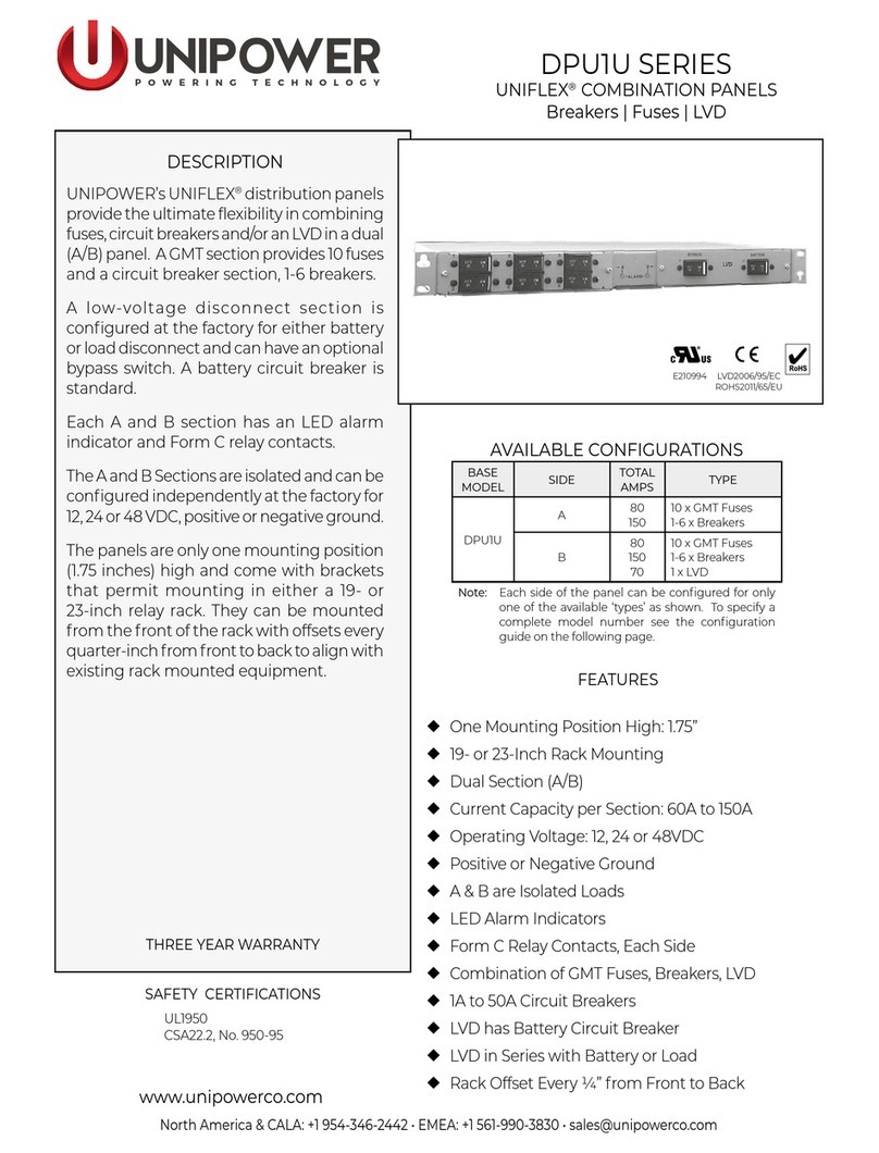
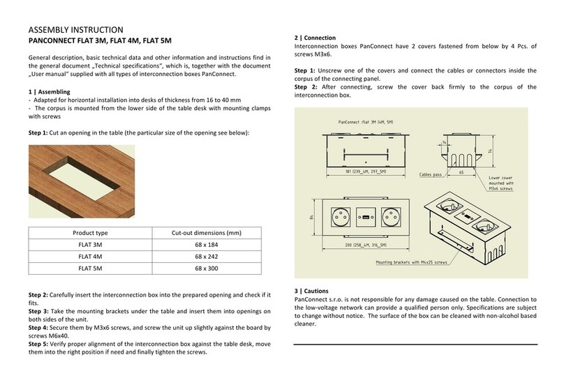
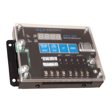
Unipower DPB1U SERIES User manual

Page 2
DPB1U & DPG1U SERIES
OPERATING MANUAL
POWERING TECHNOLOGY
Manual No. DPB-DPG-4 dpb_dpg-man-rev4-0317.indd
Contents
1.0 INTRODUCTION ...............................................................................................................4
2.0 FEATURES & OPTIONS....................................................................................................5
3.0 PRODUCT LINE.................................................................................................................5
4.0 SAFETY & INDUSTRY STANDARDS.............................................................................6
5.0 WARRANTY (summary) ....................................................................................................6
6.0 DESCRIPTION OF OPERATION......................................................................................7
7.0 SPECIFICATIONS..............................................................................................................8
8.0 FRONT PANEL DESCRIPTION........................................................................................8
9.0 BACK PANEL DESCRIPTION........................................................................................10
10.0 UNPACKING AND INSPECTION...................................................................................13
11.0 INSTALLATION...............................................................................................................14
12.0 SETUPAND TESTING ....................................................................................................16

Page 3
DPB1U & DPG1U SERIES
OPERATING MANUAL
POWERING TECHNOLOGY
Manual No. DPB-DPG-4 dpb_dpg-man-rev4-0317.indd
FIGURES
Figure 1. DPG1U & DPU1U Front Views....................................................................................4
Figure 2. Block Diagram...............................................................................................................7
Figure 3. DPB1U Front Panel View..............................................................................................8
Figure 4. DPG1U Front Panel View..............................................................................................8
Figure 5. Back Panel View..........................................................................................................10
Figure 6. Input Bus Bar Detail ....................................................................................................10
Figure 7. Output Barrier Strip Detail...........................................................................................11
Figure 8. Alarm Contact & Ground Detail..................................................................................12
Figure 9. Series Connection of Multiple Panels..........................................................................14
TABLES
Table 1. Basic Congurations......................................................................................................5
Table 2. LED State Denitions....................................................................................................7
Table 3. GMT Fuse Values...........................................................................................................9
Table 4. Input Cable Lug Sizes & Types ...................................................................................11
Table 5. Alarm Relay Contacts..................................................................................................12
Table 6. Relay State Denitions ................................................................................................12

Page 4
DPB1U & DPG1U SERIES
OPERATING MANUAL
POWERING TECHNOLOGY
Manual No. DPB-DPG-4 dpb_dpg-man-rev4-0317.indd
OPERATING MANUAL
DPB1U & DPG1U SERIES
DC POWER DISTRIBUTION PANELS
1.0 INTRODUCTION
These distribution panels provide protected power distribution to telecommunication equipment.
They oer fuse or circuit breaker positions on the A and B sides of the panel. The A and B loads
of the distribution panel are totally independent and isolated from each other. There is a green/red
LED for each load to indicate normal operation or an open circuit due to a blown fuse or tripped
circuit breaker.
The panels areonly 1.75inches (1 mountingposition) high tominimize rack spaceand canbe mounted
in either a 19- or 23-inch relay rack with corresponding brackets. They can be mounted from the
front of the rack with osets every ¼-inch from front to back to align with existing rackmounted
equipment.
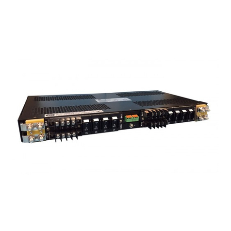
Figure 1 shows the two series of panels. The rst is the DPG1U Series which has 10 GMT fused
circuits on bothAand B sides. The second is the DPB1U Series with up to 6 circuit breaker circuits
on both A and B sides.
DPG1U: GMT Fuse Distribution Panel
DPB1U: Circuit Breaker Distribution Panel
Figure 1. DPG1U & DPU1U Front Views
The panels can be congured for 12, 24 or 48 volts and are polarity neutral. Because the A and B
sides are independent and isolated, they can be congured separately. For example, the A side can
be 48V and the B side can be 24V. The voltage and of each side must be congured at the factory..
Each bus (Aand B) has a green/red visual alarm and one Form C relay alarm contact for connection
to external audible or visual alarms.

Page 5
DPB1U & DPG1U SERIES
OPERATING MANUAL
POWERING TECHNOLOGY
Manual No. DPB-DPG-4 dpb_dpg-man-rev4-0317.indd
2.0 FEATURES & OPTIONS
2.1 The following is a summary of the important features of the Series.
Thin Height: 1.75 inches (1RU)
19 or 23-Inch Rack Mounting
Dual A/B Loads
Current Capacity: 80 to 150A per Load (Depends on Model)
Operating Voltage: 12, 24 or 48VDC
POLARITY NEUTRAL
Red/Green LED Indicators
1 Form C Relay Contacts per bus
Protection: GMT Fuses or Magnetic Circuit Breakers
Independent and Isolated Loads
Input Connections: Crimp Type Lugs
Output Connections: Barrier Terminal Strips
2.2 Options. There are two standard options available:
Option S - This option internally links the A bus to the B bus so that a fully congured unit
can be supplied DC from a single feed. TheA and B sides must have the same voltage and
polarity. Not available with option F.
Option F (special order only) - Fail safe operation for 24 and 48V units. Aand B sides with
separate feeds operate redundantly so that one feed takes over both sides in case of failure of
the other feed. Voltage and polarity of both sides must be the same. Note that this option
requires an extended depth chassis. Not available with option S.
3.0 PRODUCT LINE
The following table shows the basic conguration that are available for each type of panel. ‘x’
denotes the voltage and polarity. Full conguration details are given in section 8.
INPUT
FEEDS MAX. #
BREAKERS / FUSES AMPS
EACH FEED TOTAL
AMPS BASE MODEL
16 Breakers 150 150 DPB1U-Ax
12 Breakers 150 150 DPB1U-Ax-Bx-S
2 6 Breakers Each Bus 150 300 DPB1U-Ax-Bx
110 Fuses 80 80 DPG1U-Ax
20 Fuses 80 80 DPG1U-Ax-Bx-S
2 10 Fuses Each Bus 80 160 DPG1U-Ax-Bx
Table 1. Basic Congurations

Page 6
DPB1U & DPG1U SERIES
OPERATING MANUAL
POWERING TECHNOLOGY
Manual No. DPB-DPG-4 dpb_dpg-man-rev4-0317.indd
4.0 SAFETY & INDUSTRY STANDARDS
4.1 DPB1U & DPG1U Series power distribution panels meet the following safety requirements:
STANDARD
UL60950-1, 2nd Edition
CSA22.2 No. 60950-1, 2nd Edition
EN60950-1, 2nd Edition
4.2 DPB1U & DPG1U Series power distribution panels are CE marked to indicate conformance
to the European Union’s Low Voltage, EMC and RoHS Directives.
4.3 Inadvertent short circuiting of the system battery and/or rectier by mis-connection or
other error could be harmful. This product should be handled, tested and installed only by
qualied technical persons who are trained in the use of power systems and are well aware
of the hazards involved.
4.4 When operating this Distribution Panels the chassis ground terminal must be connected to
the system frame ground or other proper safety ground for the protection of personnel.
4.5 All connections to the Distribution Panels should be carefully checked for errors before
applying power to them.
4.6 The internal circuits maypresent an energy hazardous. The top covershould not be removed.
There are no user-serviceable components in these units. Removing the top cover will void
the warranty.
5.0 WARRANTY (summary)
DPB1U & DPG1U Series power distribution panels are warranted for two (2) years from date of
shipment against defects in material and workmanship. This warranty does not extend to products
which have been opened, altered or repaired by persons other than persons authorized by the
manufacturer or to products which become defective due to acts of God, negligence or the failure
of customer to fully follow instructions with respect to installation, application or maintenance.
For a complete text of UNIPOWER’s warranty conditions please request a copy from your local
Sales Oce.

Page 7
DPB1U & DPG1U SERIES
OPERATING MANUAL
POWERING TECHNOLOGY
Manual No. DPB-DPG-4 dpb_dpg-man-rev4-0317.indd
6.0 DESCRIPTION OF OPERATION
6.1 Power Distribution Circuits. A simplied schematic diagram of the distribution panels
is shown in Figure 2. The battery input to each load connects to a high-current copper bus
bar from which the individual fuses or circuit breakers distribute power to the loads. The
return input connects to a similar bus bar to which the individual loads terminate. The A
and B loads are totally independent and isolated with the exception of models incorporating
the ‘S’ option.
CIRCUIT
BREAKERS
or
GMT FUSES
BATT. BATT.
INPUT
RET.
INPUT
RET.
HI-CURRENT BUS BAR HI-CURRENT BUS BAR
LOADS LOADS
1 2 3... N N ...3 2 1
A SIDE
ALARM
CIRCUITS
b SIDE
ALARM
CIRCUITS
A SIDE B SIDE
-S OPTION
-S OPTION
Figure 2. Block Diagram
6.2 Alarm Circuits. The alarm circuits detect a tripped circuit breaker or blown and, in this
event, turn on the red part of the LEDs. The alarm circuits also each drive Form C relay
contacts. If one or more circuits open or if there is an input power failure, the relays are
de-energized and the contacts are used to control external audible or visual alarms. The A
and B alarm circuits are also independent and isolated from each other.
LED STATE MEANINGS
LED State Meaning
Green OK
Red
Breaker Trip
or
Breaker OFF
or
Fuse Blown
OFF No Input Power
Table 2. LED State Denitions

Page 8
DPB1U & DPG1U SERIES
OPERATING MANUAL
POWERING TECHNOLOGY
Manual No. DPB-DPG-4 dpb_dpg-man-rev4-0317.indd
7.0 SPECIFICATIONS
The following specications are typical at 25°C unless otherwise noted.
INPUT / OUTPUT
Panel Capacity ...........................................See Panel Conguration Table
Conguration
DPB1U
Single Bus .............................................................. 1 to 12 Breakers
Dual Bus..........................................................1 to 6 Breakers Each
DPG1U
Single Bus ...........................................................1 to 20 GMT Fuses
Dual Bus.....................................................1 to 10 GMT Fuses Each
Breaker/Fuse Capacity1 ............................................................. ½A to 50A
Voltage2
48V Nominal..........................................................................42-60VDC
24V Nominal..........................................................................21-30VDC
12V Nominal.......................................................................10.5-15VDC
Polarity.....................................................................POLARITY NEUTRAL
ALARMS
Alarm Indicator .....................................................Dual-Color LED Per Bus
LED Status Indication........................................................Green = Normal
Red = Alarm
O = No Power
Alarm Connections.............................One Form C Relay Contact Per Bus
SAFETY STANDARDS..............................................UL1950, UL60950-1
CAS22.2 No.950-1, EN60950-1
ENVIRONMENTAL
Operating Temp. Range ..................................................... -10°C to +70°C
Storage Temp. Range........................................................ -40°C to + 85°C
Humidity........................................................0% to 95%, Non-Condensing
PHYSICAL SPECIFICATIONS
Case Material ......................................................................................Steel
Finish............................................................................Powder Coat Black
Dimensions3, Inches (mm)................................1.75 H x 19.00 W x 9.00 D
(44.5 x 483 x 229)
Weight ....................................................................... 10.30 lbs. ( 4.67 kg.)
Rack Mounting Width ....................................................... 19 or 23 Inches
CONNECTIONS
Input Connections.......................................Crimp Type Lug or ¼ - 20 Stud
Output Connections
1-30A.................................................. Barrier Terminal Strips, No. 6-32
40A-50A............................................ Barrier Terminal Strips, No. 10-32
Chassis Ground Connection..................................................No. 8-32 Stud
Fail Alarm Connections...........................................045” sq. Wirewrap Pins
NOTES: 1. See tables for available breaker & fuse sizes.
2. See Ordering Guide to specify voltage.
3. For units with fail safe option the case depth is 10.44 inches (265mm).
8.0 FRONT PANEL DESCRIPTION
The front panel of the DPB1U, shown in Figure 3 below, consists of the A and B sides and a center
section. TheAand B sides can each accommodate up to 6 hydraulic magnetic circuit breakers rated
from 1A to 50A.
Alarm
Contacts
Alarm LEDs
B Input
¼-20 Studs
BAT
RTN
BAT
RTN
1 2 3 4 5 6 7 8 9 10
A B
ALARM
Ground
8-32 Stud
A Side Breakers B Side Breakers
A Outputs
6-32 Terminal Strip
B Outputs
6-32 Terminal Strip A Input
¼-20 Studs
BAT
RTN
BAT
RTN
1 2 3 4 5 6 7 8 9 10
B SIDE A SIDE
NO-C-NC NO-C-NC
5
6
3
4
1
2
OFF
OON
I
15
OFF
OON
I
15
OFF
OON
I
15
OFF
OON
I
15
OFF
OON
I
15
OFF
OON
I
15
5
6
3
4
1
2
OFF
OON
I
15
OFF
OON
I
15
OFF
OON
I
15
OFF
OON
I
15
OFF
OON
I
15
OFF
OON
I
15
17.12 (434.9)
1.74
(44.2)
REAR VIEW
FRONT VIEW
Case depth: 8.94 (227.1)
2.28
(57.8)
Clear Perspex
Safety Cover
Figure 3. DPB1U Front Panel View
The front panel of the DPG1U, shown in Figure 4 below, consists of the A and B sides and a center
section. TheA and B sides can each accommodate up to 10 GMT Fuses rated from ½Ato 12A.
Alarm LEDs
A B
ALARM
A Side Fuses B Side Fuses
1 10 1 10
17.12 (434.9)
FRONT VIEW
1.74
(44.2)
Figure 4. DPG1U Front Panel View
In both cases the center section has two green/red LEDs, one for the A side (left) and the other for
the B side (right). At the bottom of this center section is a slot for a wallet and designator card. This
card permits the recording of each output circuit by number.
Page 9
DPB1U & DPG1U SERIES
OPERATING MANUAL
POWERING TECHNOLOGY
Manual No. DPB-DPG-4 dpb_dpg-man-rev4-0317.indd
8.1 DPB1U Conguration Details
Notes: 1. If section B is not used a blank panel is installed at the factory and the “-B” in the
model number is not required.
2. The sum of all fuse currents on either side must not exceed 150 Amperes.
3. When the ‘S’ option is specied each side of the panel is limited to 75A.
4. Failsafe (option F) is to special order only and uses a chassis 10.44” depth. Call
sales to discuss your requirements.
Model No.: DPB1U-A -B -C-
CODE OPTION
FFail Safe 1, 2
SSingle Bus 12-way ²
1. 24 or 48V versions only.
2. Voltage and polarity for A & B
sides must be the same.
CODE VOLTAGE
1 48V
4 24V
6 12V
POLARITY NEUTRAL.
May be connected for Positive or
Negative Ground operation.
BREAKERS
CODE AMPS
F 1
G 2.5
H 5
I 10
J 15
K 20
L 25
M 30
N 40
O 50
Clear Plastic
Rear Safety Cover
(supplied as standard)
8.2 DPG1U Conguration Details
Model: DPG1U-A-B-C-
1. 24 or 48V versions only.
2. Voltage and polarity for A & B sides
must be the same.
CODE OPTION
FFail Safe 1, 2
SSingle Bus 20-way ²
CODE VOLTAGE
1 48V
4 24V
6 12V
POLARITY NEUTRAL.
May be connected for Positive or
Negative Ground operation. Clear Plastic Rear Safety Cover
(supplied as standard)
Notes: 1. If section B is not used a blank panel is installed at the factory and the “-B” in the model number is not required.
2. The sum of all fuse currents on either side must not exceed 80 Amperes.
3. When the ‘S’ option is specied each side of the panel is limited to 75A.
4. Failsafe (option F) is to special order only and uses a chassis 10.44” depth. Call sales to discuss your requirements.
GMT FUSES (ORDER SEPARATELY)
AMPS PART NUMBER COLOR AMPS PART NUMBER COLOR
½ 401-1500-0010 Red 3 401-1500-0060 Blue
¾ 401-1500-0020 Brown 5 401-1500-0070 Green
1 401-1500-0030 Gray 10 401-1500-0080 Red/White
11/3401-1500-0040 White 12 401-1500-0090 Green/Yellow
2 401-1500-0050 Orange DUMMY 401-1500-0100
Table 3. GMT Fuse Values
UNIPOWERrecommendsBussmanfuseswhichcanbeorderedusingthepartnumbersshown.

Page 10
DPB1U & DPG1U SERIES
OPERATING MANUAL
POWERING TECHNOLOGY
Manual No. DPB-DPG-4 dpb_dpg-man-rev4-0317.indd
9.0 BACK PANEL DESCRIPTION
9.1 Back View. Figure 5 shows the back of the DPB1U and DPG1U distribution panel. Inputs
are at the left and right ends of the back panel. Side B outputs are at two rows of barrier
terminal strips on the left side, and side A outputs are the same on the right side. At the
center of the back panel are two spring clamp terminal blocks for the Form C relay contact
outputs.
Below these is a chassis ground terminal.
Alarm
Contacts
Alarm LEDs
B Input
¼-20 Studs
BAT
RTN
BAT
RTN
1 2 3 4 5 6 7 8 9 10
A B
ALARM
Ground
8-32 Stud
A Side Breakers B Side Breakers
A Outputs
6-32 Terminal Strip
B Outputs
6-32 Terminal Strip A Input
¼-20 Studs
BAT
RTN
BAT
RTN
1 2 3 4 5 6 7 8 9 10
B SIDE A SIDE
NO-C-NC NO-C-NC
5
6
3
4
1
2
OFF
OON
I
15
OFF
OON
I
15
OFF
OON
I
15
OFF
OON
I
15
OFF
OON
I
15
OFF
OON
I
15
5
6
3
4
1
2
OFF
OON
I
15
OFF
OON
I
15
OFF
OON
I
15
OFF
OON
I
15
OFF
OON
I
15
OFF
OON
I
15
17.12 (434.9)
1.74
(44.2)
REAR VIEW
FRONT VIEW
Case depth: 8.94 (227.1)
2.28
(57.8)
Clear Perspex
Safety Cover
Figure 5. Back Panel View
9.2 Input Connections. See Figure 6. The DC power inputs to the distribution panels are made
by means of crimp type lugs or direct connection to ¼-20 studs to two copper bus bars on
side A and side B. The upper bus bar is the battery connection (whether + or -) and the
lower bus bar is the return (whether + or -).
0.625”
1.48”
0.5”
0.34”
0.375”
0.65”
0.32”
Figure 6. Input Bus Bar Detail
9.3 Crimp Type Lugs. A list of compatible crimp type lugs is shown in the following table
for AWG wire sizes from no. 1 to 8 and one- or two- hole lugs. These lugs can be ordered
directly from the manufacturer, Panduit Corp., using the model numbers shown in table 4.
Astandard kit of four two-hole crimp type lugs for no. 6AWG copper wire is available from
UNIPOWER. Order kit no. 775-1434-0000.

Page 11
DPB1U & DPG1U SERIES
OPERATING MANUAL
POWERING TECHNOLOGY
Manual No. DPB-DPG-4 dpb_dpg-man-rev4-0317.indd
WIRE
AWG .25DIA.
HOLES PANDUIT CORP.
PART NUMBER UNIPOWER
PART NUMBER
81
2LCA8-14-L
LCD8-14A-L 625-1665-0010
625-1665-0110
61
2LCA6-14-L
LCD6-14A-L 625-1665-0020
625-1665-0120
41
2LCA4-14-L
LCD4-14A-L 625-1665-0030
625-1665-0130
21
2LCA2-14-Q
LCD2-14A-Q 625-1665-0040
625-1665-0140
11
2LCA1-14-E
LCD1-14A-E 625-1665-0050
625-1665-0150
Table 4. Input Cable Lug Sizes & Types
9.4 Output Connections. Output connections forA and B loads are shown in Figure 5. There
are 10 sets of barrier terminal strip connections for each side, A and B. The connections
are numbered to correspond with the numbers of the front panel breakers. The upper strip
connections are from the battery through the breakers; the lower strip connections are the
returns. Side B is on the left and side A on the right, as shown.
Each terminal is a no. 6-32 screw and is rated at 30 amperes. Wire sizes from no. 10 AWG
up to no. 22AWG may be used for connections. Figure 7 below shows detailed spacing of
the terminals.
When DPB1U is tted with either 40A or 50A breakers the additional load rating is
accomodated by tting adaptors that bridge two barrier strip terminals and provide a single
#10-32 screw. Minimum wire size for these connections is 8 AWG.
A maximum of two high current breakers is allowed on each bus.
1 2 3 4 5 6 7 8 9 10
40-50A
LOADS
#10-32
1A to 30A
LOADS
#6-32
0.75
(19.1)
0.5
(12.7)
0.378
(9.60)
Figure 7. Output Barrier Strip Detail

Page 12
DPB1U & DPG1U SERIES
OPERATING MANUAL
POWERING TECHNOLOGY
Manual No. DPB-DPG-4 dpb_dpg-man-rev4-0317.indd
9.5 Form C Relay Contact Outputs. The center of the back panel has connections to the
Form C relay contact outputs for connection to external audible or visual alarm circuits.
See Figure 8.
Alarm
Contacts
Alarm LEDs
B Input
¼-20 Studs
BAT
RTN
BAT
RTN
1 2 3 4 5 6 7 8 9 10
A B
ALARM
Ground
8-32 Stud
A Side Breakers B Side Breakers
A Outputs
6-32 Terminal Strip
B Outputs
6-32 Terminal Strip A Input
¼-20 Studs
BAT
RTN
BAT
RTN
1 2 3 4 5 6 7 8 9 10
B SIDE A SIDE
NO-C-NC NO-C-NC
5
6
3
4
1
2
OFF
OON
I
15
OFF
OON
I
15
OFF
OON
I
15
OFF
OON
I
15
OFF
OON
I
15
OFF
OON
I
15
5
6
3
4
1
2
OFF
OON
I
15
OFF
OON
I
15
OFF
OON
I
15
OFF
OON
I
15
OFF
OON
I
15
OFF
OON
I
15
17.12 (434.9)
1.74
(44.2)
REAR VIEW
FRONT VIEW
Case depth: 8.94 (227.1)
2.28
(57.8)
Clear Perspex
Safety Cover
Figure 8. Alarm Contact & Ground Detail
Connection is made via two Phoenix Contact spring clamp terminal blocks. “B SIDE” is
for the Form C relay contact of side B and “A SIDE” is for the Form C relay contact of side
A. The terminals, viewed from left to right, are the normally open (NO) common (C) and
normally closed (NC) contacts, respectively. See table 5 below.
PIN FUNCTION CONTACT SCHEMATIC
NC N.C. (normally closed)
RELAY
C
ONTACTS
OUTPUTS
N.C.
C
N.O.
C C (common)
NO N.O. (normally open)
Table 5. Alarm Relay Contacts
“Normally Closed” and “Normally Open” are dened with the distribution panel powered
and providing power to all outputs, i.e. no circuit breakers tripped AND when the input
power is connected to a side (A or B), the Form C relay of that side is energized. If there
is either loss of input power, one or more circuit breakers trip or the relay is de-energized,
the normally open contacts close and the normally closed contacts open. See table 6.
RELAY STATE MEANINGS
Relay State Meaning
Energized (N.C. is closed) OK
De-energized
(N.C. is open)
Breaker Trip
or
Breaker OFF
or
Fuse Blown
No Input Power
Table 6. Relay State Denitions

Page 13
DPB1U & DPG1U SERIES
OPERATING MANUAL
POWERING TECHNOLOGY
Manual No. DPB-DPG-4 dpb_dpg-man-rev4-0317.indd
The ratings of the relay contacts are 0.6A at 125VAC or 2A at 30VDC. The spring clamp
terminals accept wire sizes nos. 16 to 26 AWG.
9.6 Chassis Ground Connection. Just below the Form C relay contact terminals is the chassis
ground terminal. This terminal is a no. 8-32 stud with a nut.
NOTE THAT IT IS ESSENTIAL THAT THIS TERMINAL IS CONNECTED TO THE
SYSTEM FRAME GROUND TO ENSURE SAFE OPERATION.
10.0 UNPACKING AND INSPECTION
10.1 This power distribution panel was carefully tested, inspected and packaged for shipment
from our factory. The unit and circuit breakers are shipped separately. Upon receipt of the
unit it should be carefully unpacked and inspected for any damage in shipment.
10.2 If there is evidence of damage, do not attempt to test the unit. The freight carrier should
be notied immediately and a claim for the cost of the rectier system should be led with
the carrier for direct reimbursement. Be sure to include the model and serial number of the
damaged unit in all correspondence with the freight carrier. Also save the shipping carton
and packing material as evidence of damage for the freight carrier’s inspection.
10.3 UNIPOWER will cooperate fully in case of any shipping damage investigation.
10.4 Always save the packing materials for later use in shipping the unit. Never ship the rectier
system without proper packing.

Page 14
DPB1U & DPG1U SERIES
OPERATING MANUAL
POWERING TECHNOLOGY
Manual No. DPB-DPG-4 dpb_dpg-man-rev4-0317.indd
11.0 INSTALLATION
11.1 Mounting. This distribution panel can be mounted in either 19- or 23-inch racks by using
the supplied reversible brackets. Mount it from the front of the rack using the correct osets
to align with existing rack-mounted equipment.
The bracket osets are every quarter inch from front to back.
11.2 Power Connections. Input connections should be made with one- or two-terminal crimp
type lugs using copper wire size from no. 1 to 8 AWG, depending on current and wire loop
distance. See Sections 9.2 and 9.3. Output connections are made to the barrier terminal
strips. See Section 9.4 and Figure 7.
11.2.1 Single feed models with option S -Although these models have both left and right
side input bus bars tted, it is only necessary to connect the input feed to one side
for correct operation. As the unused side is directly connected to the live input
feed it can be used for supplying additional panels in series. See gure 9 below.
BAT
RTN
BAT
RTN
1 2 3 4 5 6 7 8 9 10
SIDE A
SIDE B
BAT
RTN
BAT
RTN
1 2 3 4 5 6 7 8 9 10
ALM B ALM A
NO-C-NC NO-C-NC
BAT
RTN
BAT
RTN
1 2 3 4 5 6 7 8 9 10
SIDE A
SIDE B
BAT
RTN
BAT
RTN
1 2 3 4 5 6 7 8 9 10
ALM B ALM A
NO-C-NC NO-C-NC
BAT
RTN
BAT
RTN
1 2 3 4 5 6 7 8 9 10
SIDE A
SIDE B
BAT
RTN
BAT
RTN
1 2 3 4 5 6 7 8 9 10
ALM B ALM A
NO-C-NC NO-C-NC
80A/150A MAX. FEED
RETURN
Figure 9. Series Connection of Multiple Panels
When deploying panels with option S, either individually or in a chain, the following
must be adhered to so as to meet with UL safety requirements:
a) The maximum load drawn through the breaker/fuse outputs either side of the
panel may not exceed 75A.
b) The current drawn from one panel in the chain to the next is limited to 75A less
the total amount being drawn through the breaker/fuse outputs on all previous
panels in the chain.
CAUTION:BOTHPAIRSOFINPUTBUSBARSARECONNECTEDINTERNALLY
ANDMAYPRESENTANENERGYHAZARD. THESAFETYCOVERMUSTBE
FITTEDWHENINSTALLATIONHASBEENCOMPLETEDTOMINIMIZERISK.
11.3 AlarmConnections. Form C relay contact output connections are made to the spring clamp
terminal blocks. See Section 9.5. The chassis ground connection is made to the no. 8-32
stud. See Section 9.6. This safety ground connection should be made before operating the
panel.

Page 15
DPB1U & DPG1U SERIES
OPERATING MANUAL
POWERING TECHNOLOGY
Manual No. DPB-DPG-4 dpb_dpg-man-rev4-0317.indd
11.4 CheckingConnections. Carefully check the polarity of inputconnections to the distribution
panel and output connections to the load before operating the panel. Reverse connections
will not harm the distribution panel as it is POLARITYNEUTRAL. However it may cause
serious harm to the load. Check to make sure that the chassis safety ground connection is
made. Make sure that all connections are clean and secure to minimize contact resistance.
11.5 Rear Safety Cover. Once all of the above have been completed, t the clear plastic safety
cover to the back of the unit using the supplied mounting studs and screws. Instruction for
tting the mounting studs the panel are included in the accessory kit.

Page 16
DPB1U & DPG1U SERIES
OPERATING MANUAL
POWERING TECHNOLOGY
Manual No. DPB-DPG-4 dpb_dpg-man-rev4-0317.indd
This document is believed to be correct at time of publication and UNIPOWER LLC accepts no responsibility for
consequences from printing errors or inaccuracies. Specications are subject to change without notice.
12.0 SETUP AND TESTING
12.1 It is not necessary to have the distribution panel mounted in a rack for initial testing. This
can be done on a bench. It is also not necessary to have loads connected to the panel for
this testing.
12.2 With the input power source o, connect the input wires to the A side of the distribution
panel. Connect ground to the chassis ground terminal. Insert all fuses into fuse holders or
set all circuit breakers to on.
12.3 Turn on the input power source. The A side LED should be green. If it is red, one of the
fuses is blown or a circuit breaker is tripped. If the LED is o, there is no input power to
the unit. Check the output voltage at each set of output terminals with a digital voltmeter.
12.4 With the A side LED green, use an ohmmeter to check the Form C relay contact outputs.
On J4 measure the resistance between pins 1 and 2. This should read “open”. Measure the
resistance between pins 2 and 3. This should read “short”.
12.5 On the A side insert a blown fuse into fuse no. 1 position or trip circuit breaker no. 1. The
A side LED should turn red. On the upper row (side A) of wire wrap terminals, measure
the resistance between pins 1 and 2 and between pins 4 and 5. Both should read “open”.
Measure the resistance between pins 2 and 3 and between pins 5 and 6. Both should read
“short”. Replace the blown fuse with a good one or reset the circuit breaker.
12.6 On the A side check each succeeding fuse by replacing it with a blown fuse, or breaker by
tripping it, and verify that the LED turns red. It is not necessary to recheck the Form C
relay contacts.
12.7 Repeat the same tests of Sections 12.2 through 12.6 on the B side of the distribution panel.
Refer to table 5.
12.8 The distribution panel may now be connected to its intended application.
12.9 If the distribution panel did not operate properly in the above tests, go back and double
check the connections and the polarity of the input source to make sure it is correct.
Please note that there are no user serviceable parts inside and that opening the unit will void
the warranty.
If you are unable to resolve any problem call your nearest UNIPOWER sales oce for
support:
US +1 954 346 2442 UK +44 (0)1903 768200
This manual suits for next models
1
Table of contents
Other Unipower Power Distribution Unit manuals

Unipower
Unipower 1U Series User manual

Unipower
Unipower UNIFLEX DRU1U Series User manual

Unipower
Unipower DPP2U Series User manual

Unipower
Unipower PDUAC3U-120-08 User manual

Unipower
Unipower DPP1U-A1 User manual

Unipower
Unipower Sageon II 200A (N+1) User manual

Unipower
Unipower DPP1U Series User manual

Unipower
Unipower Sageon II User manual

Unipower
Unipower DPBF1U Series User manual