Unipulse F325 User manual

01JUN2015REV.1.01
DIGITAL INDICATOR
F325
OPERATION MANUAL

Introduction
I
Introduction
I
Introduction
F325 is a digital indicator for strain gauge type sensors (DIN96×48mm size).
It is ideal for the quality control of production lines such as pressure load control (press, pressure, force,
etc.) and torque control of rotating machines.
RS-485 (Protocol is Modbus-RTU or UNI-Format.) is equipped as standard and can be easily introduced to
a constituent system using Modbus protocol.
Be sure to read this operation manual before use in order to take full advantage of the superb quality of the
F325 and to use it properly and safely. Use this indicator with accurate understanding of the contents. Keep
this operation manual in a safe place to be used for further reference.
Safety precautions
Make sure that installation, maintenance, and inspection of the F325 are performed by personnel with
electrical expertise.
In this manual, precautions for safe use of the F325 are separately described as and
in the following text. The precautions described in this text are important contents related to
safety. Use this indicator with accurate understanding of the contents.
Be sure to read for safety.
Warning
Events that may cause death or severe injury to personnel in the event of misuse.
Caution
Events that may cause injury to personnel or material damage in the event of misuse.
Warning
Caution

Warning
II
Warning
II
Warning
●Prepare a safety circuit outside the F325 so that the entire system functions safely if the
F325 fails or malfunctions.
●Be sure to contact our sales representative before use if the F325 will be used as follows:
- if the indicator is used in an environment not described in the operation manual;
- if the indicator is used in a way that causes substantial effects on medical devices,
transportation equipment, entertainment devices, safety devices, etc.
●Do not disassemble, repair, or alter the F325. Fire or electric shock may occur.
●Do not install into the following environments:
- Locations with corrosive gas or combustible gas;
- Locations over which water, oil, or chemical splash
●Do not connect commercial power supply directly to a signal I/O terminal.
●Be sure to perform class D grounding when installing the main unit
●The AC cable included is for use in Japan and the rating is AC125V, 7A. Prepare a separate
AC cable if the indicator is used at a voltage higher than the rating or is used overseas.
●Be sure to check that the power is off before the following actions:
- Removal and installation of optional connectors and so forth;
- Wiring and connection of cables to a signal I/O terminal;
- Connection to protective grounding terminals.
●Be sure to check signal names and pin assignment numbers and to wire cables properly
before connecting to a signal I/O terminal.
●Make sure to attach the terminal block cover included after wiring power supply. Electric
shock may occur.
●Be sure to check wiring and so on carefully before turning power on.
●Use power supply voltage and load within the specified range and rating.
●Do not damage power cords. Fire or electric shock may occur.
●Do not touch a signal I/O terminal while the power is on. This may cause electric shock and
malfunction.
●Electric shock may occur inside when the cover of the main unit is opened. Internal
capacitors are charged even if power supply is cut off. Contact us for inspection and repair of
internal parts.
●Turn power off and unplug power cable immediately if smoke, abnormal smell, or abnormal
noise is detected.
Events that may cause death or severe injury
to personnel in the event of misuse.
Design warning
Installation warning
Wiring warning
Startup/maintenance warning

Caution
III
Caution
III
Caution
●The F325 must be incorporated into the control panel and so forth.
●Do not install into the following environments:
- Locations where temperature or humidity exceeds specifications;
- Locations subjected to drastic temperature fluctuations or icing and condensing;
- Outdoors or locations above 2,000m;
- Locations exposed to direct sunlight;
- Locations subject to dust accumulation;
- Locations with poor ventilation;
- Locations with a lot of salt and metal powder;
- Locations where the main unit is subject to direct vibration and shock.
●Perform adequate shielding if the indicator is used in the following locations:
- Near power lines;
- Locations subject to strong electric field and magnetic field;
- Locations subject to noise such as static electricity and relays.
●Install as far away as possible from equipment generating high frequency, high voltage,
large current, surge, etc. Perform wiring of cables separately from these power lines. Do not
perform parallel wiring and identical wiring.
●Do not use the indicator if damaged.
●Tighten signal I/O terminal screws to the torque specified.
Loose tightening may cause short-circuiting, fire, or malfunction.
Tightening torque: 0.2 to 0.6N・m
●Use shielded cables for cables (sensors, external I/O, options).
●Be sure to have a time interval of five seconds or longer between turning power on and off.
●Use after warming up for 30 minutes or longer following the startup of power supply.
●Protective performance of the F325 may be lost if it is not used as specified.
●Care
- Unplug the power supply during maintenance.
- Do not wipe with a wet cloth, benzin, thinner, alcohol, etc. Doing so may cause
discoloration or deformation of the F325.
When dirty, clean using a cloth soaked in diluted neutral detergent followed by a soft, dry
cloth.
Events that may cause injury to personnel or
material damage in the event of misuse.
Installation precautions
Wiring precautions
Startup/maintenance precautions

Caution
IV
Caution
IV
Compliance with EC directives
The F325 digital indicator is a product that complies with EC Directives (based on the European
Community Council) included with CE mark.
- Low Voltage Directive EN61010-1:2010 (overvoltage category II) *1
EN62311:2008 (test distance: 10cm) *1
- EMC Directive EN61326-1:2006
EN55011:2009, A1:2010 Group1, ClassA *2
EN61000-3-2:2006, A1:2009, A2:2009 *1
EN61000-3-3:2008 *1
EN61000-4-2:2009
EN61000-4-3:2006, A1:2008, A2:2010
EN61000-4-4:2004, A1:2010
EN61000-4-5:2006
EN61000-4-6:2009
EN61000-4-8:2010
EN61000-4-11:2004 *1
*1: AC spec. only
*2: Radiated only for DC spec.
Caution
●Although the F325 package is designed to absorb shock sufficiently during shipping, re-use
of the same packaging materials may damage the indicator when shock is encountered.
When sending this product to us for repair and so on, package it using sufficient shock-
absorbing materials.
●Dispose of as industrial waste.
Events that may cause injury to personnel
or material damage in the event of misuse.
Transportation precautions
Disposal precautions
Only for DC spec., the combination of the main unit of the F325 and a lightning surge
protector conforms to EN61000-4-5 (lightning surge immunity) in the EMC Directives.
Refer to P.23 “ ◇Lightning surge protector connection” for information regarding light-
ning surge protector connection.
EN62311 (human exposure) in the Low Voltage Directives conforms at the distance of
10cm.
Key points

Products supporting RoHS directive
V
Products supporting RoHS directive
V
Products supporting RoHS directive
The parts and accessories used in this machine (including the operation manual, package box and so on)
support RoHS Directive, which regulates the use of toxic substances that may have adverse effects on the
environment and human body.
RoHS directive
RoHS stands for Restriction on Hazardous Substances. This is an EU regulation regarding toxic
substances. This Directive prohibits the use of six specific substances in electrical/electronic equipment
products sold in the EU region. The six substances include lead, mercury, cadmium, hexavalent chromium,
PBB (polybrominated biphenyl) and PBDE (polybrominated diphenyl ether).
Contact one of our sales representatives for options supporting RoHS.
Key points

Contents
VI
Contents
VI
Contents
1 Outline . . . . . . . . . . . . . . . . . . . . . . . . . . . . . . . . . . . . . . . . . . . . . . . . . . . . . . 1
1-1. Package contents . . . . . . . . . . . . . . . . . . . . . . . . . . . . . . . . . . . . . . . . . . . . . . . . . . . . . 1
1-2. Connection with other devices . . . . . . . . . . . . . . . . . . . . . . . . . . . . . . . . . . . . . . . . . . . 2
1-3. Name and function of each part . . . . . . . . . . . . . . . . . . . . . . . . . . . . . . . . . . . . . . . . . . 2
■Front panel . . . . . . . . . . . . . . . . . . . . . . . . . . . . . . . . . . . . . . . . . . . . . . . . . . . . . 2
■Rear panel. . . . . . . . . . . . . . . . . . . . . . . . . . . . . . . . . . . . . . . . . . . . . . . . . . . . . . 5
1-4. Operating procedures. . . . . . . . . . . . . . . . . . . . . . . . . . . . . . . . . . . . . . . . . . . . . . . . . . 8
2 Installation & Connection . . . . . . . . . . . . . . . . . . . . . . . . . . . . . . . . . . . . . . . . 9
2-1. Installation to panel. . . . . . . . . . . . . . . . . . . . . . . . . . . . . . . . . . . . . . . . . . . . . . . . . . . 10
2-2. Connection to the signal I/O terminal block . . . . . . . . . . . . . . . . . . . . . . . . . . . . . . . . 11
2-3. Connection of strain gauge type sensors . . . . . . . . . . . . . . . . . . . . . . . . . . . . . . . . . . 12
2-4. Connection of analog monitor output (VOL OUT) . . . . . . . . . . . . . . . . . . . . . . . . . . . 13
2-5. Connection of RS-485 (RS-485 or SI/F standard: not specified at the time of order) . 14
2-6. SI/F Connection (RS-485 or SI/F specified at the time of order: SIF) . . . . . . . . . . . . 15
2-7. External output connection . . . . . . . . . . . . . . . . . . . . . . . . . . . . . . . . . . . . . . . . . . . . . 16
2-8. External input connection . . . . . . . . . . . . . . . . . . . . . . . . . . . . . . . . . . . . . . . . . . . . . . 17
2-9. Power input terminal connection . . . . . . . . . . . . . . . . . . . . . . . . . . . . . . . . . . . . . . . . 19
■AC spec. . . . . . . . . . . . . . . . . . . . . . . . . . . . . . . . . . . . . . . . . . . . . . . . . . . . . . . 19
■DC spec. (specified at the time of order). . . . . . . . . . . . . . . . . . . . . . . . . . . . . . 21
3 Setting Procedure . . . . . . . . . . . . . . . . . . . . . . . . . . . . . . . . . . . . . . . . . . . . 24
3-1. Setting mode configuration. . . . . . . . . . . . . . . . . . . . . . . . . . . . . . . . . . . . . . . . . . . . . 24
3-2. Setting items display. . . . . . . . . . . . . . . . . . . . . . . . . . . . . . . . . . . . . . . . . . . . . . . . . . 26
3-3. Setting procedure . . . . . . . . . . . . . . . . . . . . . . . . . . . . . . . . . . . . . . . . . . . . . . . . . . . . 28
4 Calibration . . . . . . . . . . . . . . . . . . . . . . . . . . . . . . . . . . . . . . . . . . . . . . . . . . 29
4-1. Calibration method . . . . . . . . . . . . . . . . . . . . . . . . . . . . . . . . . . . . . . . . . . . . . . . . . . . 29
4-2. Actual load calibration procedures . . . . . . . . . . . . . . . . . . . . . . . . . . . . . . . . . . . . . . . 30
4-3. Equivalent input calibration procedures . . . . . . . . . . . . . . . . . . . . . . . . . . . . . . . . . . . 30
4-4. Calibration LOCK release. . . . . . . . . . . . . . . . . . . . . . . . . . . . . . . . . . . . . . . . . . . . . . 31
■Calibration LOCK setting method . . . . . . . . . . . . . . . . . . . . . . . . . . . . . . . . . . . 31
4-5. Excitation voltage . . . . . . . . . . . . . . . . . . . . . . . . . . . . . . . . . . . . . . . . . . . . . . . . . . . . 31
■Excitation voltage setting method . . . . . . . . . . . . . . . . . . . . . . . . . . . . . . . . . . . 31

Contents
VII
Contents
VII
4-6. Decimal place setting (Omit if there is no change.) . . . . . . . . . . . . . . . . . . . . . . . . . . 32
■Decimal place setting method . . . . . . . . . . . . . . . . . . . . . . . . . . . . . . . . . . . . . . 32
4-7. Min. scale division setting (Omit if there is no change.) . . . . . . . . . . . . . . . . . . . . . . . 32
■Min. scale division setting method . . . . . . . . . . . . . . . . . . . . . . . . . . . . . . . . . . 32
4-8. Zero calibration. . . . . . . . . . . . . . . . . . . . . . . . . . . . . . . . . . . . . . . . . . . . . . . . . . . . . . 33
4-9. Actual load calibration . . . . . . . . . . . . . . . . . . . . . . . . . . . . . . . . . . . . . . . . . . . . . . . . 33
4-10.Equivalent input calibration . . . . . . . . . . . . . . . . . . . . . . . . . . . . . . . . . . . . . . . . . . . . 34
4-11.Calibration LOCK . . . . . . . . . . . . . . . . . . . . . . . . . . . . . . . . . . . . . . . . . . . . . . . . . . . . 35
■Calibration LOCK setting method . . . . . . . . . . . . . . . . . . . . . . . . . . . . . . . . . . . 35
5 Settings and Operations Related to Indicated Values . . . . . . . . . . . . . . . . . 36
5-1. Display frequency. . . . . . . . . . . . . . . . . . . . . . . . . . . . . . . . . . . . . . . . . . . . . . . . . . . . 36
■Display frequency setting method . . . . . . . . . . . . . . . . . . . . . . . . . . . . . . . . . . . 36
5-2. Analog filter . . . . . . . . . . . . . . . . . . . . . . . . . . . . . . . . . . . . . . . . . . . . . . . . . . . . . . . .36
■Analog filter setting method. . . . . . . . . . . . . . . . . . . . . . . . . . . . . . . . . . . . . . . . 36
5-3. Moving average filter . . . . . . . . . . . . . . . . . . . . . . . . . . . . . . . . . . . . . . . . . . . . . . . . . 37
■Moving average filter setting method . . . . . . . . . . . . . . . . . . . . . . . . . . . . . . . . 37
5-4. Sampling rate . . . . . . . . . . . . . . . . . . . . . . . . . . . . . . . . . . . . . . . . . . . . . . . . . . . . . . . 37
■Sampling rate setting method . . . . . . . . . . . . . . . . . . . . . . . . . . . . . . . . . . . . . . 37
5-5. Digital low-pass filter . . . . . . . . . . . . . . . . . . . . . . . . . . . . . . . . . . . . . . . . . . . . . . . . . 38
■Digital low-pass filter setting method. . . . . . . . . . . . . . . . . . . . . . . . . . . . . . . . . 38
5-6. Motion detect . . . . . . . . . . . . . . . . . . . . . . . . . . . . . . . . . . . . . . . . . . . . . . . . . . . . . . . 39
■Motion detect setting method . . . . . . . . . . . . . . . . . . . . . . . . . . . . . . . . . . . . . . 40
5-7. Zero tracking . . . . . . . . . . . . . . . . . . . . . . . . . . . . . . . . . . . . . . . . . . . . . . . . . . . . . . . 40
■Zero tracking setting method. . . . . . . . . . . . . . . . . . . . . . . . . . . . . . . . . . . . . . . 40
5-8. Digital zero . . . . . . . . . . . . . . . . . . . . . . . . . . . . . . . . . . . . . . . . . . . . . . . . . . . . . . . . .42
■Digital zero by key operation . . . . . . . . . . . . . . . . . . . . . . . . . . . . . . . . . . . . . . . 42
■Digital zero by external signal input . . . . . . . . . . . . . . . . . . . . . . . . . . . . . . . . . 42
5-9. Digital offset . . . . . . . . . . . . . . . . . . . . . . . . . . . . . . . . . . . . . . . . . . . . . . . . . . . . . . . . 43
■Digital offset setting method . . . . . . . . . . . . . . . . . . . . . . . . . . . . . . . . . . . . . . . 43
5-10.ZERO key valid/invalid . . . . . . . . . . . . . . . . . . . . . . . . . . . . . . . . . . . . . . . . . . . . . . . . 43
■ZERO key valid/invalid setting method . . . . . . . . . . . . . . . . . . . . . . . . . . . . . . . 43
6 Setting and Operation Related to Comparison . . . . . . . . . . . . . . . . . . . . . . . 44
6-1. Output selection . . . . . . . . . . . . . . . . . . . . . . . . . . . . . . . . . . . . . . . . . . . . . . . . . . . . . 44
■Output selection setting method . . . . . . . . . . . . . . . . . . . . . . . . . . . . . . . . . . . . 44
6-2. HI limit / LO limit / HH limit / LL limit . . . . . . . . . . . . . . . . . . . . . . . . . . . . . . . . . . . . . 45
■HI limit / LO limit / HH limit / LL limit setting method . . . . . . . . . . . . . . . . . . . . . 46
6-3. HI/LO limit comparison mode . . . . . . . . . . . . . . . . . . . . . . . . . . . . . . . . . . . . . . . . . . . 47
■HI/LO limit comparison mode setting method . . . . . . . . . . . . . . . . . . . . . . . . . . 48
6-4. Hysteresis. . . . . . . . . . . . . . . . . . . . . . . . . . . . . . . . . . . . . . . . . . . . . . . . . . . . . . . . . .48
■Hysteresis setting method . . . . . . . . . . . . . . . . . . . . . . . . . . . . . . . . . . . . . . . . . 49
Contents
VIII
Contents
VIII
6-5. Alarm HI limit, Alarm LO limit . . . . . . . . . . . . . . . . . . . . . . . . . . . . . . . . . . . . . . . . . . . 50
■Alarm HI limit and Alarm LO limit setting method . . . . . . . . . . . . . . . . . . . . . . . 50
6-6. Near zero . . . . . . . . . . . . . . . . . . . . . . . . . . . . . . . . . . . . . . . . . . . . . . . . . . . . . . . . . .51
■Near zero setting method . . . . . . . . . . . . . . . . . . . . . . . . . . . . . . . . . . . . . . . . . 51
7 Settings and Operations Related to Hold. . . . . . . . . . . . . . . . . . . . . . . . . . . 52
7-1. Hold mode . . . . . . . . . . . . . . . . . . . . . . . . . . . . . . . . . . . . . . . . . . . . . . . . . . . . . . . . . 52
■Hold mode setting method . . . . . . . . . . . . . . . . . . . . . . . . . . . . . . . . . . . . . . . . 52
■Peak hold (maintaining a maximum point) . . . . . . . . . . . . . . . . . . . . . . . . . . . . 53
■Sample hold (maintaining arbitrary points) . . . . . . . . . . . . . . . . . . . . . . . . . . . . 56
7-2. Peak hold selection . . . . . . . . . . . . . . . . . . . . . . . . . . . . . . . . . . . . . . . . . . . . . . . . . . 59
■Peak hold selection setting method. . . . . . . . . . . . . . . . . . . . . . . . . . . . . . . . . . 59
7-3. Hold fix section . . . . . . . . . . . . . . . . . . . . . . . . . . . . . . . . . . . . . . . . . . . . . . . . . . . . . . 60
■Hold fix section setting method . . . . . . . . . . . . . . . . . . . . . . . . . . . . . . . . . . . . . 60
7-4. Renewal timing of hold value . . . . . . . . . . . . . . . . . . . . . . . . . . . . . . . . . . . . . . . . . . . 60
■Renewal timing of hold value setting method . . . . . . . . . . . . . . . . . . . . . . . . . . 60
7-5. Hold detection wait . . . . . . . . . . . . . . . . . . . . . . . . . . . . . . . . . . . . . . . . . . . . . . . . . . . 61
■Hold detection wait setting method . . . . . . . . . . . . . . . . . . . . . . . . . . . . . . . . . . 61
7-6. HOLD key valid/invalid . . . . . . . . . . . . . . . . . . . . . . . . . . . . . . . . . . . . . . . . . . . . . . . . 62
■HOLD key valid/invalid setting method . . . . . . . . . . . . . . . . . . . . . . . . . . . . . . . 62
8 Settings and Operations Related to SI/F Print . . . . . . . . . . . . . . . . . . . . . . . 63
8-1. Automatic printing command . . . . . . . . . . . . . . . . . . . . . . . . . . . . . . . . . . . . . . . . . . . 63
■Automatic printing setting method . . . . . . . . . . . . . . . . . . . . . . . . . . . . . . . . . . . 64
8-2. Hold value printing . . . . . . . . . . . . . . . . . . . . . . . . . . . . . . . . . . . . . . . . . . . . . . . . . . . 65
■Hold value printing setting method . . . . . . . . . . . . . . . . . . . . . . . . . . . . . . . . . . 65
9 System Settings and Operations . . . . . . . . . . . . . . . . . . . . . . . . . . . . . . . . . 66
9-1. Set value LOCK . . . . . . . . . . . . . . . . . . . . . . . . . . . . . . . . . . . . . . . . . . . . . . . . . . . . . 66
■Set value LOCK setting method . . . . . . . . . . . . . . . . . . . . . . . . . . . . . . . . . . . . 66
9-2. Password . . . . . . . . . . . . . . . . . . . . . . . . . . . . . . . . . . . . . . . . . . . . . . . . . . . . . . . . . .67
■Password setting method . . . . . . . . . . . . . . . . . . . . . . . . . . . . . . . . . . . . . . . . . 67
9-3. Self-check/Initialization . . . . . . . . . . . . . . . . . . . . . . . . . . . . . . . . . . . . . . . . . . . . . . . . 68
■Self-check . . . . . . . . . . . . . . . . . . . . . . . . . . . . . . . . . . . . . . . . . . . . . . . . . . . . . 68
■Initialization . . . . . . . . . . . . . . . . . . . . . . . . . . . . . . . . . . . . . . . . . . . . . . . . . . . . 69
9-4. I/O input check . . . . . . . . . . . . . . . . . . . . . . . . . . . . . . . . . . . . . . . . . . . . . . . . . . . . . . 70
9-5. I/O output check . . . . . . . . . . . . . . . . . . . . . . . . . . . . . . . . . . . . . . . . . . . . . . . . . . . . . 70
9-6. BCD input check. . . . . . . . . . . . . . . . . . . . . . . . . . . . . . . . . . . . . . . . . . . . . . . . . . . . . 70
9-7. BCD output check. . . . . . . . . . . . . . . . . . . . . . . . . . . . . . . . . . . . . . . . . . . . . . . . . . . . 71
9-8. RS-232C check . . . . . . . . . . . . . . . . . . . . . . . . . . . . . . . . . . . . . . . . . . . . . . . . . . . . . 72
9-9. RS-485 check . . . . . . . . . . . . . . . . . . . . . . . . . . . . . . . . . . . . . . . . . . . . . . . . . . . . . . . 72

Contents
IX
Contents
IX
9-10.Interface . . . . . . . . . . . . . . . . . . . . . . . . . . . . . . . . . . . . . . . . . . . . . . . . . . . . . . . . . . . 73
9-11.Option type . . . . . . . . . . . . . . . . . . . . . . . . . . . . . . . . . . . . . . . . . . . . . . . . . . . . . . . . .73
9-12.Version . . . . . . . . . . . . . . . . . . . . . . . . . . . . . . . . . . . . . . . . . . . . . . . . . . . . . . . . . . . . 73
10Analog Monitor Output (VOL OUT). . . . . . . . . . . . . . . . . . . . . . . . . . . . . . . . 74
11RUN Output . . . . . . . . . . . . . . . . . . . . . . . . . . . . . . . . . . . . . . . . . . . . . . . . . 75
12Interface . . . . . . . . . . . . . . . . . . . . . . . . . . . . . . . . . . . . . . . . . . . . . . . . . . . . 76
12-1.RS-485 Interface (RS-485 or SI/F standard: not specified at the time of order) . . . 76
■Communication specifications. . . . . . . . . . . . . . . . . . . . . . . . . . . . . . . . . . . . . . 76
■Connection of RS-485. . . . . . . . . . . . . . . . . . . . . . . . . . . . . . . . . . . . . . . . . . . . 77
■Setting values related to RS-485 . . . . . . . . . . . . . . . . . . . . . . . . . . . . . . . . . . . 78
■UNI-Format commands. . . . . . . . . . . . . . . . . . . . . . . . . . . . . . . . . . . . . . . . . . . 80
■Transmitting format for continuous transmission/printing . . . . . . . . . . . . . . . . . 86
■Modbus-RTU. . . . . . . . . . . . . . . . . . . . . . . . . . . . . . . . . . . . . . . . . . . . . . . . . . . 87
12-2.SI/F (RS-485 or SI/Specified at the time of order: SIF) . . . . . . . . . . . . . . . . . . . . . . 107
■Connection of SI/F . . . . . . . . . . . . . . . . . . . . . . . . . . . . . . . . . . . . . . . . . . . . . 107
■Regarding indicated values transmitted by SI/F . . . . . . . . . . . . . . . . . . . . . . . 107
13Options . . . . . . . . . . . . . . . . . . . . . . . . . . . . . . . . . . . . . . . . . . . . . . . . . . . . 108
13-1.BCD data output. . . . . . . . . . . . . . . . . . . . . . . . . . . . . . . . . . . . . . . . . . . . . . . . . . . . 108
■Setting values related to BCD data input . . . . . . . . . . . . . . . . . . . . . . . . . . . . 109
■Sink type (BCO option) . . . . . . . . . . . . . . . . . . . . . . . . . . . . . . . . . . . . . . . . . . 110
■Source type (BSC option) . . . . . . . . . . . . . . . . . . . . . . . . . . . . . . . . . . . . . . . . 113
13-2.D/A converter . . . . . . . . . . . . . . . . . . . . . . . . . . . . . . . . . . . . . . . . . . . . . . . . . . . . . . 117
■Voltage output (DAV option) . . . . . . . . . . . . . . . . . . . . . . . . . . . . . . . . . . . . . . 117
■Current output (DAI option) . . . . . . . . . . . . . . . . . . . . . . . . . . . . . . . . . . . . . . . 119
■Setting values related to D/A converter. . . . . . . . . . . . . . . . . . . . . . . . . . . . . . 121
13-3.RS-232C interface . . . . . . . . . . . . . . . . . . . . . . . . . . . . . . . . . . . . . . . . . . . . . . . . . . 123
■Communication specifications. . . . . . . . . . . . . . . . . . . . . . . . . . . . . . . . . . . . . 123
■Cables . . . . . . . . . . . . . . . . . . . . . . . . . . . . . . . . . . . . . . . . . . . . . . . . . . . . . . . 123
■Setting values related to RS-232C . . . . . . . . . . . . . . . . . . . . . . . . . . . . . . . . . 124
■Communication format for commands . . . . . . . . . . . . . . . . . . . . . . . . . . . . . . 126
■Setting value communication format . . . . . . . . . . . . . . . . . . . . . . . . . . . . . . . . 129
■Continuous transmitting format . . . . . . . . . . . . . . . . . . . . . . . . . . . . . . . . . . . 132
14 Error Message Display. . . . . . . . . . . . . . . . . . . . . . . . . . . . . . . . . . . . . . . . 133
■Over scale display. . . . . . . . . . . . . . . . . . . . . . . . . . . . . . . . . . . . . . . . . . . . . . 133
■Calibration error display . . . . . . . . . . . . . . . . . . . . . . . . . . . . . . . . . . . . . . . . . 133
■Error message display . . . . . . . . . . . . . . . . . . . . . . . . . . . . . . . . . . . . . . . . . . 133

Contents
X
Contents
X
15Specifications. . . . . . . . . . . . . . . . . . . . . . . . . . . . . . . . . . . . . . . . . . . . . . . 134
15-1.Specifications . . . . . . . . . . . . . . . . . . . . . . . . . . . . . . . . . . . . . . . . . . . . . . . . . . . . . . 134
■Analog section. . . . . . . . . . . . . . . . . . . . . . . . . . . . . . . . . . . . . . . . . . . . . . . . . 134
■Display section . . . . . . . . . . . . . . . . . . . . . . . . . . . . . . . . . . . . . . . . . . . . . . . . 135
■Setting section. . . . . . . . . . . . . . . . . . . . . . . . . . . . . . . . . . . . . . . . . . . . . . . . . 135
■External I/O signal . . . . . . . . . . . . . . . . . . . . . . . . . . . . . . . . . . . . . . . . . . . . . . 136
■Interface . . . . . . . . . . . . . . . . . . . . . . . . . . . . . . . . . . . . . . . . . . . . . . . . . . . . . 137
■Options . . . . . . . . . . . . . . . . . . . . . . . . . . . . . . . . . . . . . . . . . . . . . . . . . . . . . . 138
■General performance . . . . . . . . . . . . . . . . . . . . . . . . . . . . . . . . . . . . . . . . . . . 140
■Accessories . . . . . . . . . . . . . . . . . . . . . . . . . . . . . . . . . . . . . . . . . . . . . . . . . . . 140
15-2.Dimensions. . . . . . . . . . . . . . . . . . . . . . . . . . . . . . . . . . . . . . . . . . . . . . . . . . . . . . . . 141
■Standard . . . . . . . . . . . . . . . . . . . . . . . . . . . . . . . . . . . . . . . . . . . . . . . . . . . . . 141
■When BCO/BSC option is selected . . . . . . . . . . . . . . . . . . . . . . . . . . . . . . . . . 142
■When DAV / DAI option is selected. . . . . . . . . . . . . . . . . . . . . . . . . . . . . . . . . 143
■When RS-232C option is selected . . . . . . . . . . . . . . . . . . . . . . . . . . . . . . . . . 144
15-3.F325 block diagram . . . . . . . . . . . . . . . . . . . . . . . . . . . . . . . . . . . . . . . . . . . . . . . . . 145
16Setting Values List . . . . . . . . . . . . . . . . . . . . . . . . . . . . . . . . . . . . . . . . . . . 146

1
1 Outline
1
Outline
Chapter
1
1-1. Package contents
The following items are included in the package box.
Be sure to check the contents before use.
1Outline
㪇㪇㪤㪘㪰㪉㪇㪈㪊㪩㪜㪭㪅㪈㪅㪇㪇
ᵢᵧᵥᵧᵲᵟᵪᴾᵧᵬᵢᵧᵡᵟᵲᵭᵰ
F325
F325 main unit F325 operation manual F325 AC input cord*
Conversion plug forTerminator Connector for BCD output
* Included only in AC specifications
AC input cord*
--- One unit --- One copy --- One piece
--- One piece
(included only in RS-485 specifications)
--- One set
(BCO and BSC output option is selected) --- One piece
AC input cord
The input cable included as standard with this product may be used with AC100V
power supply in Japan (nominal rated voltage AC125V).
When using this product overseas, use an input cable certified in that country.
Key points

2
1 Outline
2
Outline
Chapter
1
1-2. Connection with other devices
1-3. Name and function of each part
■Front panel
(1) Status display unit
Status of the F325 is displayed. Setting items are displayed when setting is performed.
HI Lighted: HI limit output condition is met
Flashes: HH limit output condition is met
* Flash is prioritized.
* HI limit output condition and HH limit output condition are subject to change
depending on setting values of HI/LO limit comparison mode and hysteresis.
OK Lighted: OK output condition is met
* OK output condition is subject to change depending on setting values of HI/LO limit
comparison mode and hysteresis.
(1) Status display unit
(2) Number display unit
(3) Setting keys

3
1 Outline
3
Outline
Chapter
1
LO Lighted: LO limit output condition is met
Flashes: LL limit output condition is met
* Flash is prioritized.
* LO limit output condition and LL limit output condition are subject to change
depending on setting values of HI/LO limit comparison mode and hysteresis.
PEAK Flashes when peak hold function is detectable.
Illuminated when peak hold function is fixed.
HOLD Illuminated when indicated values are held.
(2) Number display unit
The following three kinds of information are displayed.
1) Indicated value
2) Setting value
For setting value display, a dot illuminates during NOV RAM writing.
3) Error message display
Refer to P.133 “14.Error Message Display”.
(3) Setting keys
These keys are for commands of various settings and operations.
<When indicated values are displayed>
Setting mode is on.
Display changes to setting mode "F1".
Press the key again to stop setting.
<When setting is performed>
This key changes setting value signs (+/-).
<When indicated values are displayed>
Actual load calibration mode is on.
<When setting is performed>
This key selects set items and increases one value of the flashing digit of a setting
value.
During NOV RAM writing: Lighted
FNC
+-
GAIN CAL ZERO HOLD Valid when indicated values are displayed
Valid when setting is performed
FNC
+-
Indicated value is displayed Setting mode "F1" is displayed.
FNC
+-
FNC
+
-
GAIN

4
1 Outline
4
Outline
Chapter
1
<When indicated values are displayed>
Equivalent input calibration mode is on.
<When setting is performed>
This key selects set items and decreases one value of the flashing digit of a setting
value.
<When indicated values are displayed>
Zero calibration mode is on (when calibration LOCK is OFF).
Indicated value is forced to be zero by digital zero (when calibration LOCK is ON).
* If setting value of ZERO key valid/invalid is set as invalid and key operation is not
possible.
<When setting is performed>
This key selects a setting mode and the flashing digit of a setting value.
<When indicated values are displayed>
This key is used for hold function operation.
Operations change depending on setting values of hold fix section.
* If setting value of HOLD key valid/invalid is set as invalid, key operation is not
possible.
<When setting is performed>
The key fixes set items and setting values.
Caution
●Do not press strongly nor use sharp objects to press the switch.
This may cause damage and malfunction.
CAL
ZERO
HOLD
0: OFF
1: ON
When hold fix section is
Button down First time:
Second time:
First time:
Second time:
Third time:
Button down
Hold operation starts
Hold operation is canceled
Hold operation starts
Hold is fixed
Hold operation is canceled

5
1 Outline
5
Outline
Chapter
1
■Rear panel
(1) Protective grounding
This is a protective grounding terminal block. Be sure to ground a protective grounding terminal in
order to prevent electric shock and trouble arising from static electricity. (A case and protective
grounding terminal are in continuity.)
Do not use screws other than the ones (with bind M4x8-tooth captive washer) for installing the
main unit.
(2) Options space
One of the following options can be selected.
- BCD parallel data output (sink type) (BCO)
- BCD parallel data output (source type) (BSC)
- D/A converter (voltage output) (DAV)
- D/A converter (current output) (DAI)
- RS-232C (232)
(3) AC power terminal block
Connect AC power cord. Input power supply is AC100 to 240V.
Frequency is 50/60Hz.
* Refer to P.21 “■DC spec. (specified at the time of order)” for DC specifications.
(1) Protective
(2) Options space
(3) AC power terminal block
(4) Signal I/O grounding
terminal block

6
1 Outline
6
Outline
Chapter
1
(4) Signal I/O terminal block
This terminal block is used for inputting/outputting control signals and for inputting strain gauge
type sensor signals.
- Terminal block assignment
Upper (A) 20020009-C101B01LF made by FCI Electronics
Lower (B) 20020011-C101B01LF made by FCI Electronics
Straight type (optional) 20020000-C101B01LF made by FCI Electronics
Note: Straight type (optional) cannot be attached to both upper and lower terminal blocks.
CONTROL OUTPUT
This output terminal is used for control.
A1 COM This is a common terminal (common within output signals)
of output signals.
A2 HI This outputs HI signals. * 1
This is a PhotoMOS relay output (normally open contact).
A3 OK This outputs OK signals. * 1
This is a PhotoMOS relay output (normally open contact).
A4 LO This outputs LO signals. * 1
This is a PhotoMOS relay output (normally open contact).
A5 OUT1 This output is used for selecting a function by the setting value of
(output selection1) output selection. * 2
(HH limit, overload, RUN, hold, near zero, DZ response,
default value: HH limit (HH))
This is a PhotoMOS relay output (normally open contact).
A6 OUT2 This output is used for selecting a function by the setting value of
(output selection2) output selection. * 2
(LL limit, overload, RUN, hold, near zero, DZ response,
default value: LL limit (LL))
This is a PhotoMOS relay output (normally open contact).
A1 A10
B1 B10
A1 A2 A3 A4 A5 A6 A7 A8 A9 A10
COM*HI OK LO OUT1 OUT2 DZ HOLD
H.RESET
COM*
CONTROL OUTPUT CONTROL INPUT
* COMs of input and output are independent.
B1 B2 B3 B4 B5 B6 B7 B8 B9 B10
SHIELD +EXC -SIG -EXC +SIG + G B+ A- SG
LOADCELL VOL OUT SIF
RS-485

7
1 Outline
7
Outline
Chapter
1
*1 Refer to P.45 “6-2.HI limit / LO limit / HH limit / LL limit”and P.47 “6-3.HI/LO limit
comparison mode” for each signal.
*2 Refer to P.44 “6-1.Output selection” for output selection.
CONTROL INPUT
This input terminal is used for control.
A7 DZ This input terminal is used for controlling digital zero.
Digital zero is implemented if switched OFF -> ON.
Valid only when calibration LOCK is ON.
A8 HOLD This input terminal is used for controlling hold functions.
Refer to P.52 “7-1.Hold mode” for details.
A9 H.RESET This input terminal is used for releasing hold.
Hold is released when switched OFF -> ON.
If hold fix section is set to 0: OFF, it is not necessary to control (wire)
H.RESET since ON -> OFF of HOLD signals is also hold release at
the same time.
If hold fix section is set to 1: ON, hold will not be released since hold
is fixed by ON -> OFF of HOLD signals. Switch H.RESET OFF ->
ON to release hold.
* When HOLD signals are switched OFF -> ON from a condition
where hold is fixed, hold is released once, and it returns to the
current value and detection status.
A10 COM This is a common terminal (common within input signals) of input
signals.
LOADCELL
This terminal is used for connecting strain gauge type sensors.
B1 SHIELD This is frame ground.
Connect the shielded wires of connection cables of strain gauge
type sensors.
B2 +EXC This terminal is used for supplying voltage of strain gauge type sensors.
Connect +IN of strain gauge type sensors.
B3 -SIG This terminal is used for inputting signals of strain gauge type sensors.
Connect -OUT of strain gauge type sensors.
B4 -EXC This terminal is used for supplying voltage of strain gauge type sensors.
Connect -IN of strain gauge type sensors.
B5 +SIG This terminal is used for inputting signals of strain gauge type sensors.
Connect +OUT of strain gauge type sensors.
VOL OUT
B6 + This terminal is used for outputting voltage proportional to inputs of
strain gauge type sensors. Connect pen recorders and so on in case
that inputs of strain gauge type sensors are to be simply monitored
(approx. 2V per 1mV/V).
B7 G This is a ground terminal of VOL OUT.

8
1 Outline
8
Outline
Chapter
1
RS-485/SIF
This terminal is used for connectting RS-485 (standard: not specified at the time of order) or
SI/F (specified at the time of order, SIF).
RS-485
This serial interface is used for retrieving indicated values and status of the F325 with protocols
such as Modbus-RTU and UNI-Format and for writing settings into the F325.
B8 B+ Connect B+ of the counterpart device to be connected.
B9 A- Connect A- of the counterpart device to be connected.
B10 SG This is a ground terminal. Wiring is not normally required in case
the F325 and connection counterpart devices are class D grounded.
SI/F
This two-wire serial interface is used for connecting printers, external display units and so on
made by UNIPULSE.
B8 SI/F Connect with a SI/F terminal of the counterpart device to be connected
(no polarity).
B9 SI/F Connect with a SI/F terminal of the counterpart device to be connected
(no polarity).
B10 SG Not used.
1-4. Operating procedures
Set up the F325 according to the following procedures.
(1) Installation/connection
- Installation to panel P.10
- Connection of strain gauge type sensors P.12
- Connection of analog monitor output P.13
- Connection of RS-485 P.14
- Connection of SI/F P.15
- Connection of external output P.16
- Connection of external input P.17
- Connection of power input terminal P.19
(2) Calibration
- Calibration LOCK release P.31
- Setting of each setting value P.31~
- Zero calibration P.33
- Actual load calibration P.33
- Equivalent input calibration P.34
- Calibration LOCK P.35
(3) Setting
- Setting related to indicated values P.36
- Setting related to comparison P.44
- Setting related to hold function P.52
- Setting related to SI/F print P.63
- Setting related to system P.66
(4) Measurement start

9
2 Installation & Connection
9
Installation & Connection
Chapter
2
The following are precautions related to connection to the signal I/O terminal block.
The precautions described in this text are important contents regarding safety.
Connect this indicator with accurate understanding of the contents.
Warning
●Do not connect commercial power supply directly to the signal I/O terminal.
●To avoid electric shock when connecting to the signal I/O terminal, connect the
indicator when power is off.
●Be sure to check signal names and pin assignment numbers and to wire cables
properly before connecting to the signal I/O terminal.
●Make sure that overvoltage applied to the signal I/O terminal does not exceed the
value specified in category II.
●Make sure to attach the included terminal block cover after wiring the power supply.
Electric shock may occur.
●Be sure to check wiring and so on carefully before turning power on.
●Do not touch the I/O terminal while power is on. This may cause electric shock and
malfunction.
Caution
●Tighten power supply terminal screws to the torque specified. Loose tightening of
terminal screws may cause short-circuiting, fire, or malfunction.
Tightening torque: 0.2 to 0.6N・m
●Use shielded cables for cables.
2Installation & Connection
Table of contents
Other Unipulse Measuring Instrument manuals

Unipulse
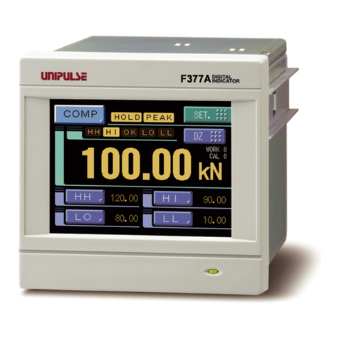
Unipulse F377A User manual

Unipulse
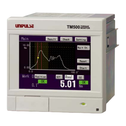
Unipulse TM500 User manual

Unipulse
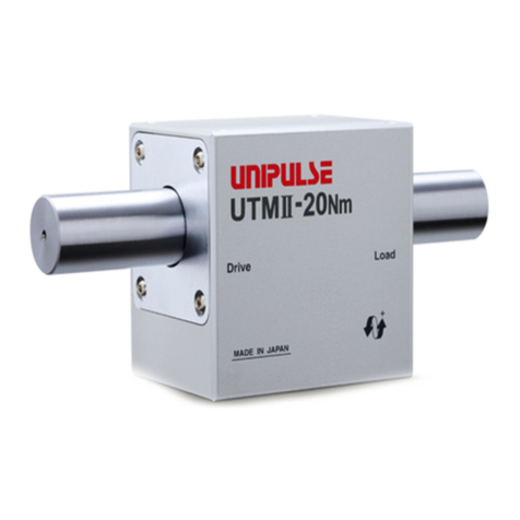
Unipulse UTM II-20Nm User manual

Unipulse
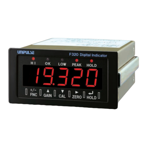
Unipulse F320 User manual

Unipulse
Unipulse USH-10KN User manual

Unipulse
Unipulse F701+ User manual

Unipulse
Unipulse F340A User manual

Unipulse
Unipulse F372A User manual

Unipulse
Unipulse TM400 User manual

Unipulse
Unipulse F370 User manual