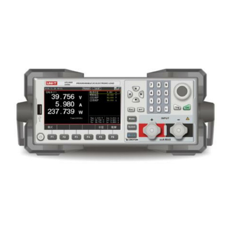
Unit UT620C User manual

110401111444X

1
Contents
Ⅰ. Safety Information .....................................................................................2
Ⅱ. Overview ...................................................................................................2
Ⅲ. Range and Accuracy .................................................................................3
Ⅳ. Technical Specifications ............................................................................ 3
Ⅴ. External Structure .....................................................................................5
Ⅵ. Operating Instructions ............................................................................... 5
1. Power on/off ................................................................................... 5
2. Check battery voltage ....................................................................5
3. Resistance precision testing .......................................................... 6
4. Backlight control .............................................................................8
5. Data hold/storage ........................................................................... 5
6. Data viewing/deletion ..................................................................... 9
7. Data upload .................................................................................... 9
8. Line resistance calibration (clear residual resistance) .................. 10
Ⅶ. Battery Description .................................................................................. 10
Ⅷ. Packing List ............................................................................................. 11

2
I. Safety Information
Thank you for purchasing the product, for better use, please read the user
manual carefully andfollow the safety information below.
Pay special attention to safety when using the product.
Do not measure any live object. Make sure that the resistor or metal object to
be measured is de-energized before measurement, otherwise, it may damage the
product.
When low battery symbol appears, please charge the product in time (the
charging time is 5~8 hours).
Please charge the battery once a month or two months if the product is not used
for a long time.
Please stop use immediately in case test lead is broken during use.
Do not place or store the product in environments with high temperature, high
humidity, dews, and direct sunlight for a long time.
Perform regular maintenance, keep product and test leadsclean. Avoid drop or
impact.
Use, dismantling or repair shall be performed by authorized professional.
If danger caused by the product occurs, please stop use and seal the product
immediately, and send it to authorized center for maintenance.
The symbol “ ” affixed at product and shown in user manual indicates user
must operate according to the instruction.
II.Overview
Digital Micro Ohm Meter (also known as Micro Ohm Meter, Ohm Meter, and DC
Resistance Tester) adopts micro-processor technology and 4-wire testing method
to make measurement safe, accurate and reliable.
The meter is mainly applied to measure resistance of conductor, contact resistance
of switch, connector and relay, resistance and contact resistance of coil, motor and
transformer winding.
It can also test connection resistance and low resistance between metal parts,
resistance and contact resistance of connecting conductors between grounding
electrode of ground grid.
The product consists of meter, monitoring software, test leads, communication
cable, etc. Featuring a large LCD, the tester enables user to view the data easily.
It can store 500 groups of data. The measured resistance ranges
ftware of master computer has multiple functions including data
viewing, data accessing, data storage, report generation, etc.
3
III. Range and Accuracy
Model
Range
Accuracy
Resolution
Max.
Testing
Current
UT620C
±0.1%FS±20dgt
(18°C~28°C;
<70%rh)
1.2A
1.2A
1.2A
1.2A
0.5A
0.05A
5mA
~100.00
0.5mA
0.05mA
Note: ±0.2%FS±20dgt (18°C~28°C; >70%rh / -10°C~50°C; <80%rh)
IV. Technical Specifications
Function
The meter is mainly applied to measure resistance of
conductor, contact resistance of switch, connector and relay,
resistance and contact resistance of coil, motor and
transformer winding. It can also test connection resistance
and low resistance between metal parts, resistance and
contact resistance of connecting conductors between
grounding electrode of ground grid.
Testing method
4-wire method
Testing current
1A
Open-circuit
voltage
4.2V
Power
8W
Power supply
DC 3.7V 2000mAh lithium battery
Backlight
Controllable backlight on off-white screen (applicable to use
in dark environments)
Display mode
LCD display; backlight on off-white screen
LCD size
71mm*52mm (L*W)
Product
dimensions
187mm*191mm*51mm (L*W*H)
Length of test
lead
About 70cm (red test lead: 1pc; black test lead: 1pc)
Measurement
time
About 2 times per second
USB port
Micro USB port

4
Communication
cable
Micro USB cable (1pc)
Data storage
Store 500 groups of data. “MEM” to indicate storage; “FULL”
to indicate full storage.
Data viewing
Symbol “MR” appears
Overrange
indication
Symbol “OL” appears
Battery voltage
Battery voltage is displayed in realtime. Please charge the
battery in time if the meter indicates low battery.
Auto power off
“APO” to indicate auto power off. The meter powers off
automatically after 15 minutes of inactivity.
Power
consumption
Standby: About 100mA (with backlight off)
Backlight: About 105mA
Measuring: 2A Max.
Weight
Meter: 480g (including battery)
Test leads: 250g
Operating
temperature and
humidity
-10°C~50°C;
<
70%rh
Storage
temperature and
humidity
-20°C~60°C;
<
70%rh
Overload
protection
AC 220V/0.0001s (C1-C2, P1-P2). After performing
overload protection, please restart the meter for normal
testing.
Insulation
resistance
Withstand
voltage
AC 3700V/rms (between circuit and casing)
Electromagnetic
characteristic
IEC61010-4-3. Electromagnetic field of radio frequency is
1V/m
Applicable
regulation
IEC61010-1, CAT III 600V, Pollution Class 2, JJG724-1991
“Verification Regulation of DC Digital Ohmmeter”, JJG166-
1993 “Verification Regulation of DC Resistors”, “DL/T967-
2005 Verification Regulation of Loop Resistance Tester and
DC Resistance High-Speed Tester”

5
V. External Structure
1. USB transmission/charging port
2. Charging indicator light
3. Connectors for test leads
4. LCD display
5. Rubber insulation protector
6. Functional buttons
7. Test leads (red: 1pc; black: 1pc)
VI. Operating Instructions
1. Power on/off
Press “ ” to power on/off the meter. “ ” appears on the bottom right corner
of the LCD after the meter powers on. The meter powers off automatically after
15 minutes of inactivity.
2. Check battery voltage
If low battery symbol “ ” appears on the LCD after the meter turns on for 2 to
4 seconds, it indicates the battery voltage is low, in such case, please charge the
battery in time. Sufficient battery voltage ensures measurement accuracy. The
battery indication bars decrease as the battery voltage decreases.

6
3. Resistance precision testing
Please clear the insulation layer and the oxidation layer on the
surface of the object to be measured before test.
Do not perform live test for resistance or DC low resistance. Live
test may damage the meter.
Test clips may be oxidized after they are used for a long time. To
ensure good contact of clips, please clear the oxide and the foreign
object at the clips.
Make sure the connection between test leads and tester/measured
object are reliable.
Component heat during test may cause error, thus it is
recommended to perform test for 30 seconds, with testing interval
at 30 seconds.
If the symbol “OL” appears during test, it indicates the resistance
between measured points exceeds the range. Please restart the
meter and then retest to troubleshoot fault caused by overload
protection, if the fault is caused by overload protection, it indicates
the measured resistor is energized, please de-energized the
measured resistor immediately and restart the meter for retesting.
Or please check if poor contact of test leads occurs (the circuit
between measured points may be open).
Measure resistance by connecting the meter with the resistor
Measured resistor RX
Black
Red

7
Measure the resistance between electric meter and down conductor
Measure the resistance between metal connectors
Metal connectors
Black
Red
Red
Black
Down conductor
Equipment
grounding wire
Grounding wire of electric meter
Copper busbar

8
Measure the resistance of contact points of relay
4. Backlight control
In power-on state, press “ ” to turn on/off backlight. The backlight function
applies in dark environments. The default state of backlight is off when powering
on the meter.
5. Data hold/storage
After the meter is powered on or measurement is completed, press “ ” to hold
the current displayed data, press “ ” to perform numbering automatically
and store current displayed data. The symbol “ ” appears on the LCD if storage
“ ” is pressed.
Red
Black
Relay

9
6. Data viewing/deletion
After the meter is powered on or measurement is completed, the meter switches
to data viewing mode and “ ” appears on the LCD when “ ” is pressed.
Press “◀” or “▶” to set the step as 1 (group), press “ ” or “ ” to set the step as
10 (groups). Press “ ” or press “ ” for twice to exit the mode and return to
testing mode.
As show below, the number “1” at top right is the number of group. If no data is
stored, “ ” appears on the LCD.
In data viewing mode, press “ ” to switch to data deletion mode. Press “ ”
or “ ” to select “ ” or “ ”. When pressing “ ” and then pressing “ ”, the data
will not be deleted and the meter returns to testing state. Press “ ” and then
press “ ” to delete all stored data. After deletion, the display is showed as below:
7. Data upload
Connect the meter with computer via USB cable, turn on the meter, then operate
the software of master computer. If USB connection is successful, the stored data
can be viewed, uploaded and saved.
The software of master computer has multiple functions including data viewing,
data accessing, data storage, etc.

10
8. Line resistance calibration (clear residual resistance)
Short-circuit both clips first, then long press “ ” for 2 to 3 seconds after the
displayed value is stabilized, to complete calibrating line resistance, as shown
below:
Note: Only when the displayed value is stabilized can “ ” be pressed.
VII. Battery Description
The charging time is 5~8 hours typically.
Please charge the battery once a month or two months if the
product is not used for a long time.
Charge the battery with the equipped original charger. The
product does not support fast charging.
The charger lights up red when charged and lights up green after
charged fully.
The product is powered by 3.7V lithium battery. If the battery voltage decreases,
the battery indication bars will decrease and the symbol “ ” will appears on the
LCD, in such situation, please charge the battery in time. Low battery voltage can
affect measurement accuracy.
Red
Black

11
VIII.Packing List
Meter
1 pc
Carrying bag
1 pc
USB cable (data transmission)
1 pc
Test lead
2 pcs (red: 1pc; black: 1pc)
Power Charger
1 pcs
User manual
1 pcs
Note:
The content of this user manual cannot be used as a reason for using the product for special
purposes.
The company is not responsible for other losses caused by use.
The company reserves the right to modify the contents of the user manual. If there are changes,
no further notice will be given.
Table of contents
Other Unit Measuring Instrument manuals