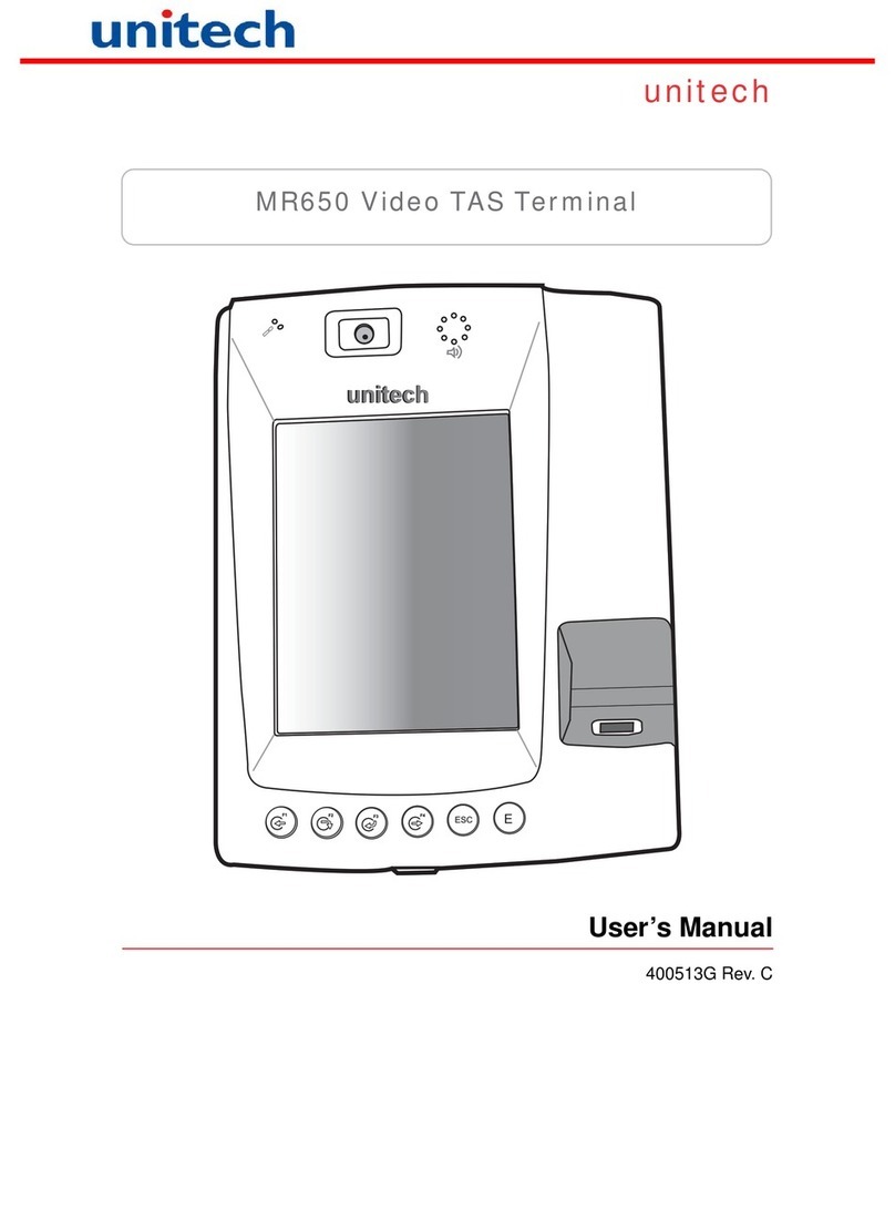
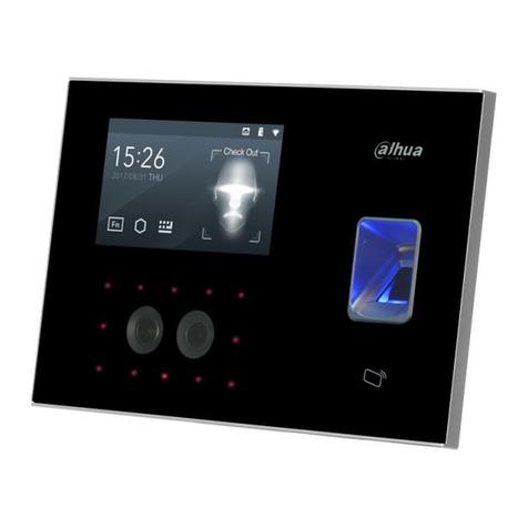
Unitech MR650 Owner's manual

MR650 Programming Manual
V 1.12 1/16/2008

- 2
1. INTRODUCTION.................................................................................................................8
1.1. Why SDK? ........................................................................................................................................................................8
1.2. How to download data from building RFID proximity reader....................................................................................8
1.3. COM definition for MR650............................................................................................................................................. 8
1.4. Useful Sample program ................................................................................................................................................... 9
2. USI.DLL - UNITECH SCANNER INTERFACE DLL .........................................................10
2.1. Register the application to the USI DLL...................................................................................................................... 10
2.2. Unregister the application from the USI.DLL.............................................................................................................11
2.3. Enable / Disable Scanner...............................................................................................................................................11
2.4. Reset Scanner.................................................................................................................................................................. 11
2.5. Get error code.................................................................................................................................................................11
2.6. Return the system error code........................................................................................................................................ 11
2.7. Get scan data...................................................................................................................................................................12
2.8. Get length of scanned data ............................................................................................................................................13
2.9. Get Symbology name .....................................................................................................................................................13
2.10. Clear scan data system buffer...................................................................................................................................14
2.11. Good read indicator...................................................................................................................................................14
2.12. Wait for acknowledgement of the last sent command............................................................................................. 14
2.13. Save setting to profiles ...............................................................................................................................................14
2.14. Save scanner setting into specified file...................................................................................................................... 14
2.15. Change scanner setting from specified setting profile ............................................................................................ 15
2.16. Automatically enable scanner beam with pressing trigger key.............................................................................. 15
2.17. Stop auto scanning function......................................................................................................................................15
2.18. Check if auto scanning is enable...............................................................................................................................15
2.19. Check if Scan2Key.exe program is running or not.................................................................................................15
2.20. Test if Scan2Key is enabled....................................................................................................................................... 17
2.21. Load/Unload Scan2Key.exe....................................................................................................................................... 17

- 3
2.22. Enable/Disable Scan2Key.......................................................................................................................................... 17
2.23. Send scanner command to decoding chip ................................................................................................................17
2.24. Only send single command decoding chip................................................................................................................ 18
2.25. Send command to decoding chip...............................................................................................................................18
3. CONTROL COMMAND FOR DECODER CHIP................................................................19
4. UNITECHAPI.DLL ............................................................................................................24
4.1. Disable ActiveSync......................................................................................................................................................... 24
4.2. Enable ActiveSync..........................................................................................................................................................24
4.3. Suspend ........................................................................................................................................................................... 24
4.4. Disable TaskBar .............................................................................................................................................................24
4.5. Enable TaskBar.............................................................................................................................................................. 25
4.6. Disable Desktop..............................................................................................................................................................25
4.7. Enable Desktop............................................................................................................................................................... 25
4.8. Disable toolbar on windows explorer ........................................................................................................................... 25
4.9. Enable toolbar on windows explorer............................................................................................................................ 25
5. SYSIOAPI.DLL (FOR HARDWARE RELATED IO CONTROL API)................................26
5.1. IO Device Control Method ............................................................................................................................................ 27
5.1.1. Create IO Device...................................................................................................................................................... 27
5.1.2. Close Device............................................................................................................................................................. 27
5.2. Access Relays..................................................................................................................................................................28
5.2.1. Check Relay Status................................................................................................................................................... 28
5.2.2. Set Relay................................................................................................................................................................... 29
5.3. Access Optical Isolated Input........................................................................................................................................ 30
5.3.1. Get Optical Isolated Input Status.............................................................................................................................. 30
5.3.2. Event for Optical Input Change................................................................................................................................ 31
5.4. Get Back Cover Open/Close status............................................................................................................................... 32
5.5. Power Control.................................................................................................................................................................34
5.5.1. Get Module 1 Power Status...................................................................................................................................... 34
5.5.2. Control Module 1 Power.......................................................................................................................................... 35
5.6. PCMCIA Control........................................................................................................................................................... 36
5.6.1. Check CF Slot .......................................................................................................................................................... 36
5.6.2. Enable/Disable CF Slot ............................................................................................................................................ 37
5.7. Camera Control.............................................................................................................................................................. 38

- 4
5.7.1. Power on/off Camera................................................................................................................................................ 38
5.7.2. Camera Reset............................................................................................................................................................ 38
5.8. Watch Dog.......................................................................................................................................................................39
5.8.1. Set time out value..................................................................................................................................................... 39
5.8.2. Start the watchdog.................................................................................................................................................... 39
5.8.3. Pause the watchdog.................................................................................................................................................. 39
6. CAMERA CONTROL - CAMERADLL.DLL ......................................................................40
6.1. Open Camera.................................................................................................................................................................. 40
6.2. Close Camera.................................................................................................................................................................. 40
6.3. Preview CCD video input .............................................................................................................................................. 40
6.4. Stop Preview CCD video input...................................................................................................................................... 40
6.5. Capture image ................................................................................................................................................................40
6.6. Get color key................................................................................................................................................................... 41
6.7. Set color key.................................................................................................................................................................... 41
6.8. Start video capture......................................................................................................................................................... 41
6.9. End video capture........................................................................................................................................................... 41
6.10. Video playback function............................................................................................................................................ 42
6.10.1. Initiate playback ....................................................................................................................................................... 42
6.10.2. Release playback...................................................................................................................................................... 42
6.10.3. Start playback........................................................................................................................................................... 42
6.10.4. Stop playback........................................................................................................................................................... 42
6.10.5. Pause playback......................................................................................................................................................... 42
6.10.6. Continue playback.................................................................................................................................................... 42
6.10.7. Check if playback..................................................................................................................................................... 43
6.11. Convert raw MPEG to standard MPEG.................................................................................................................. 43
7. FINGER PRINT CONTROL BIOIDDLL.DLL.....................................................................44
7.1. Start Finger print function............................................................................................................................................44
7.2. Stop Finger print function............................................................................................................................................. 44
7.3. Connect to Finger print module.................................................................................................................................... 44
7.4. Disconnect Finger print module.................................................................................................................................... 44
7.5. Setup Finger print module communication type......................................................................................................... 45
7.6. Get module’s communication type ...............................................................................................................................45
7.7. Set module’s communication type ................................................................................................................................ 46
7.8. Get FP module’s baudrate............................................................................................................................................. 46

- 5
7.9. Set FP module’s baudrate..............................................................................................................................................46
7.10. Get FP module’s Aux Port baudrate........................................................................................................................ 47
7.11. Set FP module’s Aux Port baudrate......................................................................................................................... 47
7.12. Set FP module’s Aux Port baudrate......................................................................................................................... 47
7.13. Get FP version ............................................................................................................................................................ 47
7.14. Initialize FP directory ................................................................................................................................................48
7.15. Read FP directory ......................................................................................................................................................48
7.16. Get template from FP module................................................................................................................................... 48
7.17. Send template to FP module...................................................................................................................................... 49
7.18. Remove template from FP module ........................................................................................................................... 49
7.19. Get globe threshold from FP module........................................................................................................................49
7.20. Set globe threshold from FP module ........................................................................................................................ 50
7.21. Enroll FP template into FP module..........................................................................................................................50
7.22. Get last time error condition..................................................................................................................................... 50
7.23. Verify FP template ..................................................................................................................................................... 51
7.24. Check if there is finger print above sensor ..............................................................................................................51
7.25. Get Max. template number........................................................................................................................................ 51
8. USEFUL FUNCTION CALL - WITHOUT INCLUDE SYSIOAPI.DLL................................52
8.1. Warm-boot, Cold-boot and power off..........................................................................................................................52
9. MIFARE READER LIBRARY............................................................................................53
9.1. Connect to Mifare Reader............................................................................................................................................. 53
9.2. Disconnect with Mifare Reader..................................................................................................................................... 53
9.3. Check the connection with Mifare Reader...................................................................................................................53
9.4. Firmware Version........................................................................................................................................................... 53
9.5. Write Key to EEPROM.................................................................................................................................................54
9.6. Load Key from EEPROM.............................................................................................................................................54
9.7. Load Key with User Defined ......................................................................................................................................... 54
9.8. Read Card’s Block Data................................................................................................................................................ 54

- 6
9.9. Write Card’s Block Data............................................................................................................................................... 55
9.10. Read Card’s Value.....................................................................................................................................................55
9.11. Write Card’s Value.................................................................................................................................................... 55
9.12. Increase Value ............................................................................................................................................................ 55
9.13. Decrease Value............................................................................................................................................................ 56
9.14. Read Sector Data........................................................................................................................................................ 56
9.15. Read Multi Sectors Data............................................................................................................................................ 56
9.16. Reader Serial Number ............................................................................................................................................... 56
9.17. Start Read Card Serial Number ...............................................................................................................................57
9.18. Stop Read Card Serial Number................................................................................................................................57
9.19. Get Card Serial Number............................................................................................................................................57
9.20. Check Reading............................................................................................................................................................57
9.21. Error Code.................................................................................................................................................................. 58
10. GET DEVICE ID................................................................................................................59
11. FLASH CONFIGURATION MANAGER - FLASHCONFIGMANAGER.DLL ....................60
11.1. Open Camera..............................................................................................................................................................60
11.2. Updating a Configuration Setting............................................................................................................................. 60
11.3. Adding a Customer Configuration Setting .............................................................................................................. 60
11.4. Deleting A Configuration Entry................................................................................................................................61
11.5. Verifying an Entry's Value........................................................................................................................................ 61
11.6. Handling Errors .........................................................................................................................................................61
12. RS485 COMMUNICATION...............................................................................................62
12.1. Why RS485?................................................................................................................................................................62
12.2. Windows APIs Used...................................................................................................................................................62
12.3. Sample code ................................................................................................................................................................ 62
12.3.1. Opening the Com Port.............................................................................................................................................. 62
12.3.2. Setting the Com Port Parameters.............................................................................................................................. 63
12.3.3. Writing Data To The Com Port................................................................................................................................ 63
12.3.4. Reading Data From The Comm Port........................................................................................................................ 64
12.3.5. Get error code...........................................................................................................................................................64

- 7
13. FUNCTION KEY SETTING ON REGISTRY .....................................................................65
14. UPDATE NOTES ..............................................................................................................66

- 8
1. Introduction
1.1. Why SDK?
Microsoft had provided several standard SDKs for different WinCE platforms because there are different
supporting modules, GUIs and components in each platform. There are un-predictable problem if user use
improper SDK to compile your application. User should select proper SDK which match to target platform to
develop application program. For Unitech terminal, we also provide SDK for each platform, you can get it
from Technical Binder, or get the latest version from below URL.
http://w3.tw.ute.com/pub/cs/SDK/MR650/MR650SDK.zip
You can also get sample source for Camera, Finger print and wave record/play from below URL
http://w3.tw.ute.com/pub/cs/software/sample_program/mr650/MR650_Sample_source.zip
1.2. How to download data from building RFID proximity reader
The major difference between the MR650 and a standard HPC/PalmPC is barcode input capability. The
WinCE Reference Manual contains no information regarding barcode input. This section will introduce the
programming structure of the barcode sub-system and the programming utility library for the MR650. Inside
the MR650 there is an advanced decoding chip to control SE900 laser engine and to handle barcode
decoding. Below is system diagram for the MR650 barcode:
According to the above diagram, the MR650 communicates with Decoder Chip by mean of serial port COM2.
Its communication parameter is fixed on 38400,N,8.1. Normally, the Decoder Chip is in sleep mode when
COM2 is not activated. When COM2 is activated, the Decoder Chip will start working, and it will decode the
barcode “signal” from the laser engine when the trigger key is pressed. After decoding, barcode data and its
symbology type will be sent directly to MR650.
Many programmers find it difficult to control the Decoder Chip via programming language alone, especially if
they are not familiar with barcode and serial port controls. Because of this, Unitech provides the following
utility library and program for the user or application programmer to control the Decoder Chip:
1. Application program “Scan2Key.exe” is a useful application program that can read input data from the
laser scanner and then directly input the data into MR650’s keyboard buffer. “Scan2Key.exe” makes
barcode data input simple, and can be especially valuable to those programmers not familiar with
COM port programming. User program simply reads the barcode data from the keyboard. For barcode
symbologies setting, you can run Scanner Setting from Control Panel to define all of supporting
symbologies and delimiter.
2. Utility library:
For programming control, MR650 provide USI.DLL to let user control scanner input, symbologies
setting and profile controlling. Please refer to for detail API lists.
1.3. COM definition for MR650
COM 1 Physical full RS232 port (ActiveSync)
COM 2 Scanner (Hamster)
COM 3 IrCom
COM 4 USB client
COM 5 RS485
COM 6 PCMCIA (if insert COM type PCMCIA card
Reader Advanced
Decoder
Chip
MR650 CPU
COM2

- 9
1.4. Useful Sample program
You can get useful sample program for VC, C# and VB.NET from below URL
http://w3.tw.ute.com/pub/cs/software/sample_program/mr650/MR650_Sample_source.zip
It includes below functions’ sample program
1. Finger print
2. Camera
3. RS485
4. Audio Wave record and play

-
2. USI.DLL - Unitech Scanner Interface DLL
2.1. Register the application to the USI DLL
Function Description:
Register the application to the USI DLL, so that the DLL can communicate with the application. It will
also open and initial scanner port (COM2, for example) and set the scanner to the working mode.
The application should call USI_Unregister to unregister from the DLL after done with the scanner.
Function call:
BOOL USI_Register(HWND hwnd, UINT msgID);
Parameter: (input)
hwnd: Handle of the window to which USI DLL will send messages to report all activities,
including error messages, scan data ready, etc.
msgID: Specifies the message to be posted. DLL will post messages by calling:
PostMessage(hwnd, msgID, msg, param).
The window procedure will receive custom message about msgID and wParam
parameter can be one of the followings:
SM_ERROR_SYS Indicates a system error, which is caused by a call to the system
function. Param contains the error code from GetLastEror().
SM_ERROR Indicates an error. Param contains the cause of error, which can be
on of followings:
SERR_INVALID_HWND: Invalid window handle.
SERR_INVALID_MSGID: msgID cannot be 0.
SERR_OPEN_SCANNER: Open or initial scanner port failed.
SERR_CHECKSUM: Checksum error in received packet.
SERR_DATALOST: New scan data is lost because data buffer is not
empty.
SERR_BUFFEROVERFLOW: Data buffer overflow. The default size is 4K bytes.
SM_REPLY Indicates received a reply. All the responses from the scanner
except the scan data will be notified by this message.
SM_DATAREADY Indicates that scan data is successfully decoded and ready to
retrieve.
SM_ACK Indicates received a ACK.
SM_NAK Indicates received a NAK.
SM_NOREAD Indicates received a No-Read packet.
Note: Scanner port settings are defined in registry as described below:
[HKEY_LOCAL_MACHINE\SOFTWARE\Unitech America Inc.\Scanner\Settings]
"COMPORT"="COM2:"
"BAUDRATE"="38400"
"STOPBITS"="1"
"PARITY"="None"
"CHECKPARITY"="1"

-
2.2. Unregister the application from the USI.DLL
Function Description:
Unregister the application from the DLL. It will close the scanner port, and by default it will disable
the scanner.
Function call:
void USI_Unregister();
Return code:
None
2.3. Enable / Disable Scanner
Function Description:
To starts or stop USI function. This function is useful for application to temporarily stop scanner
function if it is only need keypad input or keep clear input buffer.
Function call:
BOOL USI_EnableScan(BOOL bStatus);
Parameter: (input)
bStatus: TRUE : Enable Scanner
msgID: FALSE : Disable Scanner
Return code:
BOOL: TRUE : OK
FALSE : Failure
2.4. Reset Scanner
Function Description:
Set the scanner to the working mode, and reset the communication control.
Function call:
BOOL USI_Reset();
Return code:
Always TRUE
2.5. Get error code
Function Description:
Returns the error code (SERR_***).
Function call:
DWORD USI_GetError();
Return code:
Return the error code (SERR_***), which has been described in USI_Register function.
2.6. Return the system error code
Function Description:
Return the system error code, which is returned by GetLastError. It will also return the description of
the error in buffer if it is not NULL.
Function call:
DWORD USI_GetLastSysError(LPTSTR buffer, int len);
Return code:
Return the system error code, which is returned by system function GetLastError. It will also return
the description of the error in buffer retrieved by system function FormatMessage if it is not NULL.
For a complete list of error codes, refer to the SDK header file WINERROR.H.

-
2.7. Get scan data
Function Description:
Retrieve the scan data into the buffer. Return the length of characters. It also returns the barcode
type if type is not NULL. Return 0 means that the buffer is too short to hold the data. USI_GetData
should be called when SM_DATAREADY message is received. Or call USI_ResetData to discard
the data. Both of them will reset the data buffer so that next scan data can come in. If the data buffer
is not empty and a new scan data occurs, it will be discarded and an error message SM_ERROR
with code of SERR_DATALOST will be sent.
Function call:
UINT USI_GetData(LPBYTE buffer, UINT len, UINT* type);
Parameter: (input)
len: UINT : Len specifies the maximum length of the buffer.
Parameter: (output)
buffer: LPBYTE : Data buffer for storing scanned data
type: UINT : Barcode type which is defined on USI.H. Please refer to below
list
BCT_CODE_39 // Code 39
BCT_CODABAR // CodaBar
BCT_CODE_128 // Code 128
BCT_INTERLEAVED_2OF5 // Interleaves 2 of 5
BCT_CODE_93 // Code 93
BCT_UPC_A // UPC A
BCT_UPC_A_2SUPPS // UPC A with 2 Supps
BCT_UPC_A_5SUPPS // UPC A with 5 Supps
BCT_UPC_E0 // UPC E
BCT_UPC_E0_2SUPPS // UPC E with 2 Supps
BCT_UPC_E0_5SUPPS // UPC E with 5 Supps
BCT_EAN_8 // EAN 8
BCT_EAN_8_2SUPPS // EAN 8 with 2 Supps
BCT_EAN_8_5SUPPS // EAN 8 with 5 Supps
BCT_EAN_13 // EAN 13
BCT_EAN_13_2SUPPS // EAN 13 with 2 Supps
BCT_EAN_13_5SUPPS // EAN 13 with 5 Supps
BCT_MSI_PLESSEY // MSI Plessey
BCT_EAN_128 // EAN 128
BCT_UPC_E1 // UPC E1
BCT_UPC_E1_2SUPPS // UPC E1 with 2 Supps
BCT_UPC_E1_5SUPPS // UPC E1 with 5 Supps
BCT_TRIOPTIC_CODE_39 // TRIOPTIC CODE 39
BCT_BOOKLAND_EAN // Bookland EAN
BCT_COUPON_CODE // Coupon Code
BCT_STANDARD_2OF5 // Standard 2 of 5
BCT_CODE_11_TELPEN // Code 11 Telpen
BCT_CODE_32 // Code 32
BCT_DELTA_CODE // Delta Code
BCT_LABEL_CODE // Label Code IV & V
BCT_PLESSEY_CODE // Plessey Code
BCT_TOSHIBA_CODE // Toshiba Code China Postal
Code

-
2.8. Get length of scanned data
Function Description:
Return the data length of the scan data. When allocate the memory to hold the scan data, add at
least one additional byte for string terminator.
Function call:
UINT USI_GetDataLength();
Return code:
UNIT: data length
2.9. Get Symbology name
Function Description:
Returns the barcode name of the type.
Function call:
LPCTSTR USI_GetBarcodeName(UINT type, LPBYTE buffer, UINT len);
Parameter: (input)
type: UINT : Barcode type. (refer to for type definition
buffer: LPBYTE : Please refer to below table
Type Buffer
BCT_CODE_39 Code 39
BCT_CODABAR Codabar
BCT_CODE_128 Code 128
BCT_INTERLEAVED_2OF5 Interleaved 2 of 5
BCT_CODE_93 Code 93
BCT_UPC_A UPC A
BCT_UPC_A_2SUPPS UPC A with 2 Supps.
BCT_UPC_A_5SUPPS UPC A with 5 Supps.
BCT_UPC_E0 UPC E
BCT_UPC_E0_2SUPPS UPC E with 2 Supps.
BCT_UPC_E0_5SUPPS UPC E with 5 Supps.
BCT_EAN_8 EAN 8
BCT_EAN_8_2SUPPS EAN 8 with 2 Supps.
BCT_EAN_8_5SUPPS EAN 8 with 5 Supps.
BCT_EAN_13 EAN 13
BCT_EAN_13_2SUPPS EAN 13 with 2 Supps.
BCT_EAN_13_5SUPPS EAN 13 with 5 Supps.
BCT_MSI_PLESSEY MSI Plessey
BCT_EAN_128 EAN 128
BCT_TRIOPTIC_CODE_39 Trioptic Code 39
BCT_BOOKLAND_EAN Bookland EAN
BCT_COUPON_CODE Coupon Code
BCT_STANDARD_2OF5 Standard 2 of 5
BCT_CODE_11_TELPEN Code 11 or Telpen
BCT_CODE_32 Code 32 (Pharmacy Code)
BCT_DELTA_CODE Delta Code
BCT_LABEL_CODE Label Code IV & V
BCT_PLESSEY_CODE Plessey Code
BCT_TOSHIBA_CODE Toshiba Code (China Postal Code)
len: UINT : length of string on the 2nd parameter buffer
Return code:
BOOL: TRUE : If it found name for the barcode type
FALSE : If not (type may be wrong

-
2.10.Clear scan data system buffer
Function Description:
Reset the data buffer so that next new scan data can come in.
Function call:
void USI_ResetData();
2.11.Good read indicator
Function Description:
Inform a good receiving of scan data, this will play a sound (wave file scanok.wav) and light the LED
lasting for 1 second.
Function call:
void USI_ReadOK();
Note: (input)
USI will call the function GoodReadLEDOn function exported by the DLL defined in the registry
described below (UPI300.DLL is an example) to turn on and off the LED. If the DLL is not defined or
the function is not found, USI will bypass the call of GoodReadLEDOn.
[HKEY_LOCAL_MACHINE\SOFTWARE\Unitech America Inc.\Scanner\Settings]
"DLLLEDCONTROL"="UPI300.DLL"
The function prototype of GoodReadLEDOn is:
VOID WINAPI GoodReadLEDOn(BOOL fon);
Turn on when fon is TRUE, and turn off when fon is FALSE.
2.12.Wait for acknowledgement of the last sent command
Function Description:
Wait for acknowledgement of the last sent command until timeout. It is useful when a serial of
commands needs to be sent at a time. Before call USI_SendCommand, call
USI_WaitForSendEchoTO to make sure that the previous command is done.
Function call:
BOOL USI_WaitForSendEchoTO(DWORD timeout);
Parameter: (input)
timeout: DWORD : Specifies the timeout in millisecond.
Return code:
Returns FALSE if timeout.
2.13.Save setting to profiles
Function Description:
Save current settings of scanner so that the settings will be persistent when the unit get power off
and on again.
Function call:
BOOL USI_SaveCurrentSettings();
Return code:
TRUE if success, otherwise FALSE.
2.14.Save scanner setting into specified file
Function Description:
Save the current settings to file. The file takes “*.USI” as extension name.
Function call:
BOOL USI_SaveSettingsToFile(LPCTSTR filename);
Parameter: (input)
filename: LPCTSTR : file name for setting profile
Return code:
TRUE = success
FALSE = error

-
2.15.Change scanner setting from specified setting profile
Function Description:
Load and activate the settings from file.
Function call:
BOOL USI_LoadSettingsFromFile(LPCTSTR filename, BOOL formulaOnly);
Parameter: (input)
filename: LPCTSTR : name of scanner setting profile (*.USI)
formulaOnly: BOOL : if TRUE, only data editing formulas are load. The other settings
remain unchanged
Return code:
TRUE = success
FALSE = error
2.16.Automatically enable scanner beam with pressing trigger key
Function Description:
Start auto scanning. Scan engine will be automatically triggerrd on.
Function call:
BOOL USI_StartAutoScan(DWORD interval);
Parameter: (input)
interval: DWORD : Specifies the interval in milli-second
Note:
USI will call the function SetScannerOn function exported by the DLL defined in the registry
described below (UPI300.DLL is an example) to start and stop the scanner. If the DLL is not defined
or the function is not found, then auto scanning is not available.
[HKEY_LOCAL_MACHINE\SOFTWARE\Unitech America Inc.\Scanner\Settings]
"DLLSCANNERCONTROL"="UPI300.DLL"
The function prototype of SetScannerOn is:
VOID WINAPI SetScannerOn(BOOL fon);
Start when fon is TRUE, and stop when fon is FALSE.
2.17.Stop auto scanning function
Function Description:
Stop auto scanning.
Function call:
void USI_StopAutoScan();
2.18.Check if auto scanning is enable
Function Description:
Check if auto scanning function is enabled or not.
Function call:
BOOL USI_IsAutoScanning()
Return code:
BOOL: TRUE : auto-scanning is running
FALSE : auto-scanning is disabled
2.19.Check if Scan2Key.exe program is running or not
Function Description:
Test whether Scan2Key application is running at background. (It doesn't mean Scan2Key is
routing scanner input to keyboard, please call S2K_IsEnabled() to check if routing function is enable
or not).
Function call:
HWND S2K_IsLoaded();
Return code:
NULL: Scan2Key is not running
Non-NULL: indicates scan2key is running. It actually returns window handle for scan2key, but

-
it is for internal use - send messages.

-
2.20.Test if Scan2Key is enabled
Function Description:
Test whether Scan2Key is enabled. Scan2Key routes scanning input from scanner to keypad buffer,
so that barcode data can be input as like from keystrokes on keypad.
Function call:
BOOL S2K_IsEnabled();
Return code:
TRUE = enabled
FALSE = disable
2.21.Load/Unload Scan2Key.exe
Function Description:
Load or unload Scan2Key.
Function call:
BOOL S2K_Load(BOOL load, DWORD timeout);
Parameter: (input)
load: BOOL : TRUE = load Scan2Key
FALSE = unload Scan2Key
timeout: DWORD : when unload Scan2Key, it will wait until Scan2Key has been
removed from memory or timeout specified by this parameter.
Return code:
TRUE = successfully loaded
2.22.Enable/Disable Scan2Key
Function Description:
Enable or disable Scan2Key to put scanned data to standard keyboard input buffer. Scan2Key is
enabled by default.
Function call:
BOOL S2K_Enable(BOOL enable, DWORD timeout);
Parameter: (input)
enable: BOOL : TRUE = Enable scanned data to keyboard buffer
FALSE = Disable scanned data to keyboard
timeout: DWORD : when enable or disable Scan2Key, it will wait until Scan2Key has
been removed from memory or timeout specified by this parameter.
Return code:
TRUE = success
FALSE = fail
2.23.Send scanner command to decoding chip
Function Description:
Send scanner command to decoder chip. This command will send a serial of bytes to decoder chip
as following: (Esc and BCC will be calculated and added automatically)
Esc, high-length, low-length, command-ID, operation, set, BCC
Please refer to complete command reference on section
BOOL HAM_SendCommand(BYTE highlen, BYTE lowlen, BYTE cmdID, BYTE op, BYTE set);
Parameter: (input)
highlen: BYTE : high byte of command length
lowlen: BYTE : low byte of command length
cmdID: BYTE : command ID
op: BYTE : operation mode for this command
set: BYTE : operand for this command
Return code:
TRUE = Indicates the command has been successfully sent to queue to output.

-
2.24.Only send single command decoding chip
Function Description:
Send command to decoder chip. This is a variation of command HAM_SendCommand. It sends
following command to Hamster: (note, only two bytes without BCC)
Esc, 0x80+cmd
Function call:
BOOL HAM_SendCommand1(BYTE cmd);
Parameter: (input)
cmd: BYTE : command
Return code:
TRUE = Indicates the command has been successfully sent to queue to output.
2.25.Send command to decoding chip
Function Description:
Send command to decoder chip. This is a variation of command HAM_SendCommand. It will read a
number of parameters and packet them as in following format and send it to decoder chip.
Esc, parameter1, parameter2, …, BCC
The total number of parameters is specified by first parameter num.
Function call:
BOOL HAM_SendCommand2(BYTE num, BYTE parameter1, …);
Parameter: (input)
num: BYTE : number of total parameters
parameterx: BYTE : Parameter
Return code:
TRUE = Indicates the command has been successfully sent to queue to output.

-
3. Control command for decoder chip
Important: This chapter describes low level command for scanner control function. If you already USI to do
scanner programming, you don't need to care about this chapter. In general, it is not suggested to use level
command to control scanner, because there are timing issue on serial communication programming , and it
is always need communication expert to do that and it is hard to explain it on document.
When Host prepare to send a command to hamster, it must first check CTS, if CTS is high, then Host must
set the RTS to high then clear RTS to low to wake up the Hamster.
Special Command for control
command Format Comment
Control Esc,80H+SOH(01H) Let Hamster enter slaving status. At this status Hamster just
receives commands and executes it until it receives Release
command or timeout (about 10s). Otherwise, the timeout is
about 1s as the interval of commands.
Release Esc,80H+EOT(04H) Let Hamster exit from slaving status.
Execute/
Enquiry Esc,80H+ENQ(05H) Let Hamster execute the previous saved command and check
hamster if there is a result of previous executed command to
send to Host. If previous saved command have already
executed and no result to send, hamster do not reply until
there is a result. If Host receive a result but the BCC is wrong,
it can re-send ENQ to re-send result again.
ACK Esc,80H+ACK(06H) It is from Hamster to Host. If Hamster receive a command and
this command do not need send message back, Hamster
reply the ACK.
NAK Esc,80H+NAK(15H) It is from Hamster to Host. Hamster require the Host to re-
send command again, normally when received a wrong BCC,
it can send the NAK. The Hamster sends back NAK whenever
it receives a no sense command.
COMMAND FROM HOST TO HMASTER
Command format:Esc,Lh,Ll,n,m,S1,...,Si,BCC
Here: Esc is Escape code(H'1B)
Lh/Ll is command's length when the Lh.b7 is 0, Lh is high byte, Ll is low byte, count from n to BCC.
When Lh.b7=1 it is a two bytes special command.
n is command ID
m is operation: Normally for setting commands the 0 means setting, 1 default, 2 read current setting,
3 special operation. When m=1 or 2, the S1 should be 0 for bits or one character setting. If the setting is a
string, like pre_amble, the read or default command should not contain any Si byte. The special meaning
in a command please refers the command definition.
Si is setting/read data.
BCC: it equals to XOR of all the bytes before the BCC.
Conventions: S1.bj means the number j bit of byte S1.
The expression 1~64:2 means that the number is between 1 and 64, the default is 2.
Notice: Any interval in a command transmit can not exceed 1 second.
Command Format Comment
Initial/ Warm
start Esc,0,2,0,BCC Hamster initializes the ports and flags according to the setting
in RAM.
Default Esc,0,2,1,BCC Reset setting in RAM and initialize
Mpu_idle Esc,0,4,2,m,S1,BCC S1 is 0~3:0 is sleep mode,1 is watch mode,
2_is standby mode.
Beep Esc,0,4,3,m,S1,BCC S1 0 none,1 low,2_medium,3 high,4 low/high,5high/low
block_delay Esc,0,4,4,m,S1,BCC S1 is 0_10ms,1 50ms,2 100ms,3 500ms,4 1s,5 3s

-
char_delay Esc,0,4,5,m,S1,BCC S1 is 0_none,1 1ms,2 5ms,3 10ms,4 20ms,5 50ms
Function_code Esc,0,4,6,m,S1,BCC
No meaning for you S1 is 0 off,1_on
Capslock Esc,0,4,7,m,S1,BCC
No meaning for you S1 is 0_auto trace,1 lower case,2 upper case
Language Esc,0,4,8,m,S1,BCC
No meaning for you S1 is 0_U.S.,1 U.K.,2 Swiss,3 Swedish, 4 Spanish,5
Norwegian,6 Italian,7 German,8 French,9 Alt Key Mode,A
Danish
Baud_rate Esc,0,4,0D,m,S1,BCC
No meaning for you S1 is 0 300,1 600,2 1200,3 2400,4 4800,
5 9600,6 19200,7_38400
Parity Esc,0,4,0E,m,S1,BCC
No meaning for you S1 is 0 EVEN,1 ODD,2 MARK,3 SPACE,4_NONE
Data_bits Esc,0,4,0F,m,S1,BCC
No meaning for you S1 is 0 7,1_8BIT
Handshake Esc,0,4,10,m,S1,BCC
No meaning for you S1 is 0_IGNORE,1 RTS ENABLE AT POWERUP,2 RTS
ENABLE IN COMMUNICATION
Ack_nak Esc,0,4,11,m,S1,BCC
No meaning for you S1 is 0_OFF,1 ON
BCC_char Esc,0,4,12,m,S1,BCC
No meaning for you S1 is 0_OFF,1 ON
Data_direction Esc,0,4,13,m,S1,BCC
No meaning for you S1 is =0_SEND TO HOST,1 SEND TO HOST AND
TERMINAL,2 SEND TO TERMINAL
Time_out Esc,0,4,14,m,S1,BCC
No meaning for you S1 is 0_1S,1 3S,2 10S,3 UNLIMITED
Terminator Esc,0,4,15,m,S1,BCC S1 is B1B0=0_ENTER(CR/LF),1 FIELD EXIT(CR),2
RETURN(LF),3 NONE
Code_id Esc,0,4,16,m,S1,BCC S1 is 0_OFF,1 ON
Verification Esc,0,4,17,m,S1,BCC S1 is 0_OFF,1~7 1 to 7 times verification
Scan_mode Esc,0,4,18,m,S1,BCC S1 is 0_TRIGGER MODE,1 FLASH_MODE,2 MULTISCAN
MODE,3 ONE PRESS ONE SCAN,4~7 reserved
Label_type Esc,0,4,19,m,S1,BCC S1 is 0_POSITIVE,1 POSITIVE AND NEGATIVE
Aim_fuction Esc,0,4,1a,m,S1,BCC S1 is 0_DISABLE,1 ENABLE
Scan_pre_data Esc,0,L,1b,m,S1,…Si,BCC Si can be 1 to 8 CHARACTERS
Scan_post_data Esc,0,L,1c,m,S1,…Si,BCC Si can be 1 to 8 CHARACTERS
Define_code39f Esc,0,4,1d,m,S1,BCC define Code 39 full ASCII ID:Here S1 is 1 CHARACTER
Define_code39s Esc,0,4,1e,m,S1,BCC define Code 39 standard ID:Here S1 is 1 CHARACTER
Define_EAN13 Esc,0,4,1f,m,S1,BCC define EAN13 ID:Here S1 is 1 CHARACTER
Define_UPCA Esc,0,4,20,m,S1,BCC define UPC A ID: Here S1 is 1 CHARACTER
Define_EAN8 Esc,0,4,21,m,S1,BCC define EAN8 ID:Here S1 is 1 CHARACTER
Define_UPCE Esc,0,4,22,m,S1,BCC define UPC E ID:Here S1 is 1 CHARACTER
Define_I25 Esc,0,4,23,m,S1,BCC define I25 ID:Here S1 is 1 CHARACTER
Define_CDB Esc,0,4,24,m,S1,BCC define Codabar ID:Here S1 is 1 CHARACTER
Define_C128 Esc,0,4,25,m,S1,BCC define Code128 ID:Here S1 is 1 CHARACTER
Define_C93 Esc,0,4,26,m,S1,BCC define Code93 ID:Here S1 is 1 CHARACTER
Define_S25 Esc,0,4,27,m,S1,BCC define S25 ID:Here S1 is 1 CHARACTER
Define_MSI Esc,0,4,28,m,S1,BCC define MSI ID:Here S1 is 1 CHARACTER
Define_C11 Esc,0,4,29,m,S1,BCC define Code11 ID:Here S1 is 1 CHARACTER
Define_C32 Esc,0,4,2a,m,S1,BCC define Code32 ID:Here S1 is 1 CHARACTER
Define_DELTA Esc,0,4,2b,m,S1,BCC define Delta ID:Here S1 is 1 CHARACTER
Define_LABEL Esc,0,4,2c,m,S1,BCC define Label code ID:Here S1 is 1 CHARACTER
Define_PLESSEY Esc,0,4,2d,m,S1,BCC define Plessey ID:Here S1 is 1 CHARACTER
Define_TELEPEN Esc,0,4,2e,m,S1,BCC define Telepen ID:Here S1 is 1 CHARACTER
Define_TOSHIBA Esc,0,4,2f,m,S1,BCC define Toshiba ID:Here S1 is 1 CHARACTER
Define_EAN128 Esc,0,4,30,m,S1,BCC define EAN128 ID:Here S1 is 1 CHARACTER;IF H'FF, THEN
USE "]C1"
Mterminator Esc,0,4,31,m,S1,BCC
No meaning for you Here S1 is 0_ENTER,1 NONE
Sentinal Esc,0,4,32,m,S1,BCC
No meaning for you S1 is 0 not send,1 send
Other manuals for MR650
3
Table of contents
Other Unitech IP Access Controllers manuals
