V-TAC ESS Series User manual

INSTRUCTION MANUAL
ESS SERIES BATTERY PACK
IN CASE OF ANY QUERY/ISSUE WITH THE PRODUCT, PLEASE REACH OUT TO US AT: SUPPORT@V-TAC.EU
FOR MORE PRODUCTS RANGE, INQUIRY PLEASE CONTACT OUR DISTRIBUTOR OR NEAREST
DEALERS. V-TAC EUROPE LTD. BULGARIA, PLOVDIV 4000, BUL.L.KARAVELOW 9B
Thank you for selecting and buying V-TAC Product. V-TAC will serve you
the best. Please read these instructions carefully & keep this user manual
handy for future reference. If you have any another query, please contact
our dealer or local vendor from whom you have purchased the product.
They are trained and ready to serve you at the best.
INTRODUCTION
Multi-Language Manual QR CODE
Please scan the QR code to access the manual
in multiple languages.
About This Document
Intended Audience
This document is intended for:
Hardware installation engineers
Technical support engineers
Maintenance engineers
Users
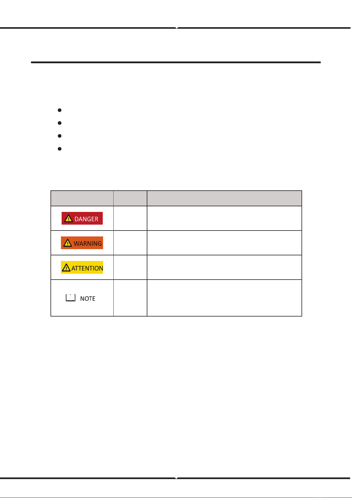
Symbol Conventions
The symbols that may be found in this document are defined as follows.
Symbol Definition Remarks
Danger Indicates a hazard with a high level of risk which, if not avoided, will
result in death or serious injury.
Warning Indicates a hazard with a medium level of risk which, if not avoided,
could result in death or serious injury.
Attention Indicates a hazard with a low level of risk which, if not avoided,
could result in minor or moderate injury.
Note
Supplements the important information in the main text.
NOTE is used to address information not related to personal injury,
equipment damage, and environmental deterioration.

2 Overview
2.1 Product Application
RESS is a next-generation product developed by V-TAC, which is used in residential energy storage solut
ions. This battery system has a capacity of 19.2 kWh or 20.48 kWh.
RESS integrates the high-performance BMS. To extend battery life, it has multiple protection functions
such as system over-charge, system over-discharge, cell over-voltage, cell under-voltage, charging over-
current, discharging over-current, and insulation fault. It also has RS485, CAN, and dry contact
communication, allowing for remote monitoring.
2.2 Product Composition
The RESS consists of one battery cabinet (two battery boxes and one chassis base inside), one high-
voltage box, and four battery modules.
The composition of the RESS is shown as follows:
Figure 1. RESS composition
(1) High-voltage box (2) Battery module (3) Battery cabinet

6
3 Components Introduction
3.1 Battery Cabinet
The appearance of the battery cabinet is shown as follows.
Figure 2. Battery cabinet appearance
The battery cabinet dimensions are shown as follows:
Figure 3. Battery cabinet dimensions (unit: mm)

7
3.2 Battery System
The battery system specifications are as follows.
Table 1. Battery system specifications
No. Items Parameter Remark
1 Rated voltage
VEH192100C: 192 V
VEH204100C: 204.8 V
2 Rated capacity 100 Ah
3 Rated energy
VEH192100C: 19.2 kWh
VEH204100C: 20.48 kWh
4 System efficiency 92% Watt-hour efficiency
5 Communication type CAN、RS485、DO/DI
6 Equalization Negative equalization ≤300 mA
7 Operation voltage range
VEH192100C: 168 V-204 V
VEH204100C: 179.2 V-217.6 V
8 Self-discharge ≤3% per month
9Max continuous charge
current 100 A
10 Max continuous discharge
current 100 A
11 Total voltage sampling 0 V-600 V ±(0.5%FS+0.1%RD)
12 Total current sampling 1 A-200 A
13 Temperature sampling NTC (-20℃~125℃) ±2℃
14 Insulation sampling 0~5MΩ
15 SOC estimate accuracy ≤8%
16 Charge ambient temperature 0℃-45℃Optimum ambient
temperature: 15℃-
35℃
17 Discharge ambient
temperature -10℃-45℃
18 Storage temperature 0℃-40℃

Copyright © Vestwoods Technology Co., Ltd. 8
No. Items Parameter Remark
19 Humidity 5%-95% RH, no condense
20 Protection
System over-voltage and system under-voltage, cell
over-voltage and cell under voltage, charging over-
current and discharging over-current, charging high
temperature and charging low temperature,
discharging high temperature and discharging low
temperature, short circuit protection, insulation
faulty protection
21 Dimensions (W×H×D) 640 mm×1280 mm×350 mm
22 Weight
VEH192100C: Approx. 230kg
VEH204100C: Approx. 238kg
3.2.1 Lithium-ion Cell
The lithium iron phosphate cell selected in the scheme is a special energy-type lithium battery product.
This series of lithium iron phosphate cells have high specific energy, longer cycle life, low cost, capable of
high current charge and discharge, high-temperature tolerance, high energy density, no battery memory
effect, safety, and pollution-free features.
3.2.1.1 Appearance
Lithium-ion cell's three views are shown as follows.
Figure 4. Lithium-ion cell three views (unit: mm)

9
3.2.1.2 Technical Specifications
Lithium-ion cell main technical specifications are shown as follows.
Table 2. Lithium-ion cell main technical specifications
No. Items Specification
1 Battery type Lithium iron phosphate
2 Model LF100MA
3 Rated voltage 3.2 V
4 Rated capacity 100 Ah
5 Rated energy 0.32 kWh
6 Max continuous charge current 100 A
7 Max continuous discharge current 100 A
8 Charging cut-off voltage 3.65 V
9 Discharging cut-off voltage 2.50 V
10 Operating charging temperature 0℃-55℃
11 Operating discharging temperature -20℃-45℃
12 Storage temperature
-20-45℃(less than 1 month);
0-35℃(less than 12 months);
13 Operating humidity 5%-95% RH
14 Cycle life ≥3500 cycle@ 25℃80%DOD
15 Size (Width*High*Depth) 160 mm×115.7 mm×50.1 mm
16 Weight About 1.92 kg
3.2.2 Battery Module
15 or 16 lithium cells are packed in the battery module, assembled in a combination of 1 parallel, 15, or
16 series.
The battery module is integrated with BMU to collect voltage and temperature and monitor the battery
module's status at all times.

10
3.2.2.1 Appearance
The battery module appearance is shown as follows.
Figure 5. Battery module appearance
The battery module's three views are shown as follows.
Figure 6. Battery module three views (unit: mm)
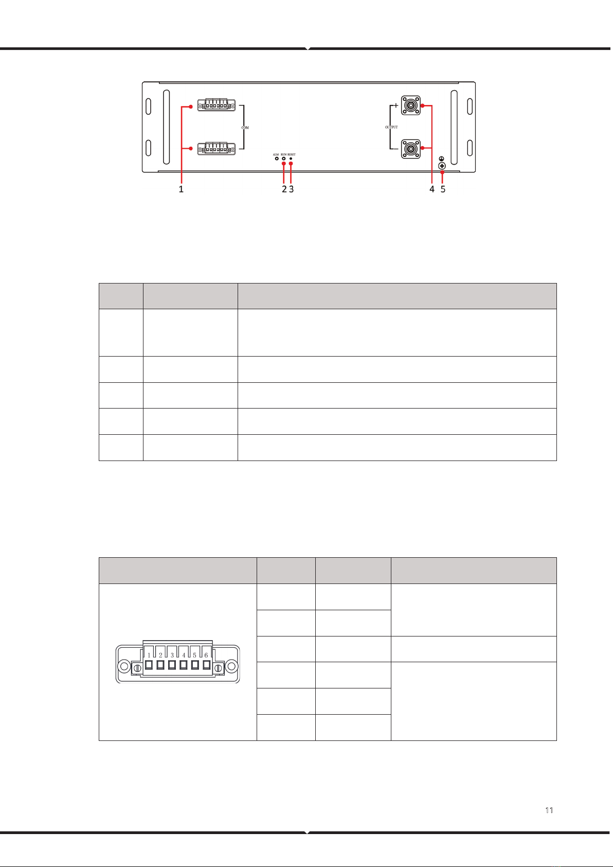
3.2.2.2 Operation Panel
The battery module operation panel is shown as follows.
11
Figure 7. Battery module operation panel
The definition of the battery module operation panel is shown as follows.
Table 3. Operation panel definition
No. Items Remark
1 Communication port
Communicate with other battery modules;
Communicate with high-voltage box.
2 Running indicator Indicate battery module running status.
3 Reset switch Reset BMU.
4 Output connectors Battery module output connectors.
5 Ground Ground.
3.2.2.3 PIN Definition
The PIN definition of a communication port is shown as follows.
Table 4. Communication port PIN definition
Location schematic diagram Location Definition Remark
1 24 V+
BMU power supply
2 24 V-
3 - -
4 CAN0H
Communication between BMU and BCU.
5 CAN0L
6 CAN0S
3.2.2.4 Technical Specifications
Copyright © Vestwoods Technology Co., Ltd. 12
The battery module's main technical specifications are shown as follows.
Table 5. Battery module main technical specifications
No. Items VT48100E-H1 VT48100E-H2
1 Model VT48100E-H1 VT48100E-H2
2 The number of cells 15 16
3 Cells in series and parallel 1P15S 1P16S
4 Model 48 V 51.2 V
5 Rated voltage 100 Ah 100 Ah
6 Rated capacity 4.80 kWh 5.12 kWh
7 Charging cut-off voltage 54.0 V 57.6 V
8 Discharging cut-off voltage 37.5 V 40.0 V
9 Max continuous charge current 100 A 100 A
10 Max continuous discharge current 100 A 100 A
11 Size (Width*High*Depth) 482 mm×130 mm×455 mm (With
the handle)
482 mm×130 mm×455 mm (With
the handle)
12 Weight About 39 kg About 41 kg
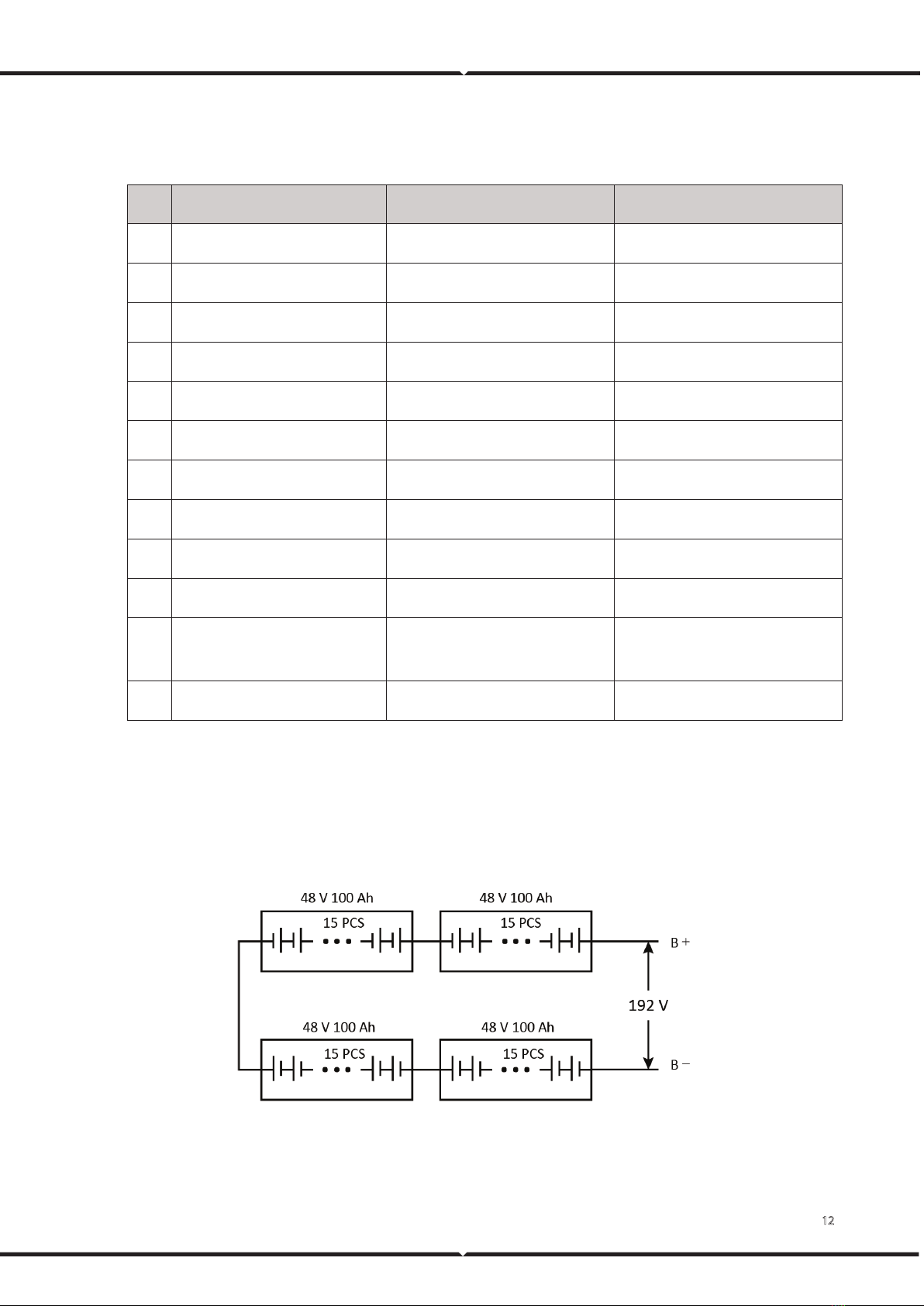
3.2.3 Battery Cluster
The battery cluster is composed of 4 battery modules. The schematic diagrams of battery clusters are
shown as follows.
Figure 8. VEH192100C battery cluster composition diagram
Other manuals for ESS Series
4
This manual suits for next models
2
Table of contents
Other V-TAC Batteries Pack manuals


Popular Batteries Pack manuals by other brands


Inventus Power
Inventus Power PROTRXion S-12V100-TRX-HD user manual

Clas Ohlson
Clas Ohlson PW-290A quick start guide

EINHELL
EINHELL MULTI-Ah Power X-Change Plus Original operating instructions

Samsung
Samsung EB-U3300 quick start guide

ECTIVE
ECTIVE LC Series instruction manual

Narada
Narada 12REXC70 Operation manual