V-TAC VT-204100 User manual

INSTRUCTION MANUAL
ESS SERIES BATTERY PACK
IN CASE OF ANY QUERY/ISSUE WITH THE PRODUCT, PLEASE REACH OUT TO US AT: SUPPORT@V-TAC.EU
FOR MORE PRODUCTS RANGE, INQUIRY PLEASE CONTACT OUR DISTRIBUTOR OR NEAREST
DEALERS. V-TAC EUROPE LTD. BULGARIA, PLOVDIV 4000, BUL.L.KARAVELOW 9B
Thank you for selecting and buying V-TAC Product. V-TAC will serve you
the best. Please read these instructions carefully & keep this user manual
handy for future reference. If you have any another query, please contact
our dealer or local vendor from whom you have purchased the product.
They are trained and ready to serve you at the best.
INTRODUCTION
Multi-Language Manual QR CODE
Please scan the QR code to access the manual
in multiple languages.
VT-204100 11527
MODEL SKU

About This Document
Intended Audience
This document is intended for:
Hardware installation engineers
Technical support engineers
Maintenance engineers
Users
Symbol Conventions
The symbols that may be found in this document are defined as follows.
Symbol Definition Remarks
Danger Indicates a hazard with a high level of risk which, if not avoided, will
result in death or serious injury.
Warning Indicates a hazard with a medium level of risk which, if not avoided,
could result in death or serious injury.
Attention Indicates a hazard with a low level of risk which, if not avoided,
could result in minor or moderate injury.
Note
Supplements the important information in the main text.
NOTE is used to address information not related to personal injury,
equipment damage, and environmental deterioration.

VT-204100
VT-204100
VT-204100
VT-204100
VT-204100

6
3Components Introduction
3.1 Battery Cabinet
The appearance of the battery cabinet is shown as follows.
Figure 2. Battery cabinet appearance
The battery cabinet dimensions are shown as follows:
Figure 3. Battery cabinet dimensions (unit: mm)

7
3.2 Battery System
The battery system specifications are as follows.
Table 1. Battery system specifications
No. Items Parameter Remark
1 Rated voltage
VEH192100C: 192 V
VEH204100C: 204.8 V
2 Rated capacity 100 Ah
3 Rated energy
VEH192100C: 19.2 kWh
VEH204100C: 20.48 kWh
4 System efficiency 92% Watt-hour efficiency
5 Communication type CAN、RS485、DO/DI
6 Equalization Negative equalization ≤300 mA
7 Operation voltage range
VEH192100C: 168 V-204 V
VEH204100C: 179.2 V-217.6 V
8 Self-discharge ≤3% per month
9 Max continuous charge
current 100 A
10 Max continuous discharge
current 100 A
11 Total voltage sampling 0 V-600 V ±(0.5%FS+0.1%RD)
12 Total current sampling 1 A-200 A
13 Temperature sampling NTC (-20℃~125℃) ±2℃
14 Insulation sampling 0~5MΩ
15 SOC estimate accuracy ≤8%
16 Charge ambient temperature 0℃-45℃Optimum ambient
temperature: 15℃-
35℃
17 Discharge ambient
temperature -10℃-45℃
18 Storage temperature 0℃-40℃


9
3.2.1.2 Technical Specifications
Lithium-ion cell main technical specifications are shown as follows.
Table 2. Lithium-ion cell main technical specifications
No. Items Specification
1 Battery type Lithium iron phosphate
2 Model LF100MA
3 Rated voltage 3.2 V
4 Rated capacity 100 Ah
5 Rated energy 0.32 kWh
6 Max continuous charge current 100 A
7 Max continuous discharge current 100 A
8 Charging cut-off voltage 3.65 V
9 Discharging cut-off voltage 2.50 V
10 Operating charging temperature 0℃-55℃
11 Operating discharging temperature -20℃-45℃
12 Storage temperature
-20-45℃(less than 1 month);
0-35℃(less than 12 months);
13 Operating humidity 5%-95% RH
14 Cycle life ≥3500 cycle@ 25℃80%DOD
15 Size (Width*High*Depth) 160 mm×115.7 mm×50.1 mm
16 Weight About 1.92 kg
3.2.2 Battery Module
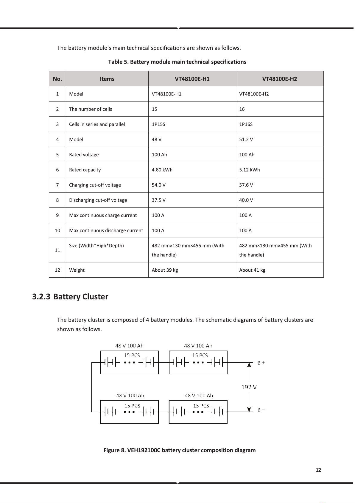
15 or 16 lithium cells are packed in the battery module, assembled in a combination of 1 parallel, 15, or
16 series.
The battery module is integrated with BMU to collect voltage and temperature and monitor the battery
module's status at all times.

10
3.2.2.1 Appearance
The battery module appearance is shown as follows.
Figure 5. Battery module appearance
The battery module's three views are shown as follows.
Figure 6. Battery module three views (unit: mm)
3.2.2.2 Operation Panel
The battery module operation panel is shown as follows.

11
Figure 7. Battery module operation panel
The definition of the battery module operation panel is shown as follows.
Table 3. Operation panel definition
No. Items Remark
1 Communication port
Communicate with other battery modules;
Communicate with high-voltage box.
2 Running indicator Indicate battery module running status.
3 Reset switch Reset BMU.
4 Output connectors Battery module output connectors.
5 Ground Ground.
3.2.2.3 PIN Definition
The PIN definition of a communication port is shown as follows.
Table 4. Communication port PIN definition
Location schematic diagram Location Definition Remark
1 24 V+
BMU power supply
2 24 V-
3 - -
4 CAN0H
Communication between BMU and BCU.
5 CAN0L
6 CAN0S
3.2.2.4 Technical Specifications


14
Figure 11. High-voltage box three views (unit: mm)
3.2.4.2 Operation Panel
The operation panel of the high-voltage box is shown as follows.
Figure 12. High-voltage box operation panel
The definition of the high-voltage box operation panel is shown as follows.
Table 6. Operation panel definition
No. Items Remark
1 DC input switch BMS 24V power supply control
2 External communication port (Master high voltage box) SCADA communication / Inverter communication
3 BMU communication port BMU power supply and communication
4 Output switch Battery output control
5 Battery input connectors Battery input connectors
6 Output connectors Battery output connectors

15
3.2.4.3 PIN Definition
External communication port
The PIN definition of an external communication port is shown as follows.
Table 7. External communication port PIN definition
Location schematic diagram Location Definition Remark
1 CAN1H BCU communication, connect the
last high voltage box
(
Optional
)
2 CAN1L
3 CAN1H BCU communication, connect the
next high voltage box
(
Optional
)
4 CAN1L
5 CAN2H
Inverter communication
6 CAN2L
7 DI+
Low voltage wake up
8 DI-
9 AC/L
AC input
10 AC/N
BMU communication port
The PIN definition of the BMU communication port is shown as follows.
Table 8. BMU communication port PIN definition
Location schematic diagram Location Definition Remark
1 V+
Battery module 24V power supply
2 V-
3 CAN0H BMU communication, connect the last
battery module
4 CAN0L
5 V+
Battery module 24V power supply
6 V-
7 CAN0H BMU communication, connect the next
battery module
8 CAN0L

VT-204100

17
Battery module management module: BMU, integrated with the battery module.
Battery cluster management module: BCU, integrated with the high voltage box.
Battery system management module: PCU, integrated with the high voltage box.
BMS can monitor the current, voltage, and temperature of cells in the battery module in real-time,
calculate the SOC of the battery system, communicate with the host computer software, and send fault
and alarm information.
The schematic diagram of the communication structure of the BMS is shown as follows.
Figure 13. Communication topology
3.3.1 BMU
The BMU integrated with the battery module is the initiating unit of the BMS. It monitors battery
voltage and temperature and transmits cell information to the BCU through the communication port.
BMU's main technical specifications are shown as follows.
Table 10. BMU main technical specifications
No. Item Specification Remark
1 Power supply 24 VDC
2 Power consumption <1 W Without equalization
3 Voltage sampling channels 15 strings Compatible with 16 strings
4 Voltage sampling range 0 V~5 V Accuracy ±10 mV
5 Temperature sampling
channel
4 cell sampling and 1 PCB
sampling
6 Temperature sampling range -20℃~125℃Accuracy ±2℃

18
No. Item Specification Remark
7 Equalization Negative equalization ≤300 mA
8 Operation temperature -20℃~75℃
9 Operation humidity 5%-95%RH
3.3.2 BCU
The BCU integrated with the high-voltage box is the intermediate level of the BMS. It collects information
from the BMU and transmits it to the PCU.
BCU can effectively manage the safety of charge and discharge of battery clusters, provide real-time
monitoring of battery parameters, fault diagnosis, SOC/SOH estimation, insulation detection, remote
monitoring, and other functions, and trigger protection when alarm and emergency battery module
possible failures appear, to ensure the safety, reliable and stable operation of battery modules.
BCU's main technical specifications are shown as follows.
Table 11. BCU main technical specifications
No. Item Specification Remark
1 Power supply 24 VDC
2 Power consumption <2 W
3 Total voltage sampling 0 V~600 V ±(0.5%FS+0.1%RD)
4 Current sampling 0 A~1000 A ±(0.5%FS+0.5%RD)
5 Temperature sampling 2 Channels, -20℃-125℃Accuracy ±2℃
6 DO 8 channels
7 DI 8 channels
8 Insulation 0~5 MΩ
Total voltage≥400 V, accuracy ±20%;
Total voltage<400 V, accuracy ±30%;
Insulation resistance≤5kΩ, accuracy ±10kΩ
9 SOC estimate accuracy ≤8%
10 Communication type CAN-3 channels, RS485-2 channels
3.3.3 PCU

19
The PCU integrated with the high-voltage box can monitor and manage battery clusters internally and
complete information exchange externally.
The main functions of the PCU are as follows:
Battery information management: PCU can monitor cell voltage, cell temperature, cluster voltage,
cluster charging current, and cluster discharging current in real-time.
SOC estimation: Estimated the battery cluster SOC.
DI/ DO communication: PCU provides multiple DI and DO interfaces.
CAN and RS485 communication: PCU provides 3 CAN communication interfaces and 2 RS485
communication interfaces.
Self-fault diagnosis: PCU has a self-test function.
Charge and discharge management: PCU can coordinate the charge and discharge between battery
clusters and improve the circulating current in clusters.


VT-204100

This manual suits for next models
2
Table of contents
Other V-TAC Batteries Pack manuals