VAC V200 POSITIONER Manual

92077r14
V200 POSITIONER
www.vacaccessories.com
1
V200 FEEDBACK OPTION

92077r14
www.vac.se
V200 POSITIONER
2
1 INTRODUCTION.................................................................................. 4
1.1 Principle of Operation.............................................................. 4
1.2 ProductIdentication............................................................... 4
1.3 Safety Instructions................................................................... 4
2 FEEDBACK INSTALLATION.............................................................. 5
2.1 Connections ............................................................................ 5
2.2 Front cover and indicator ........................................................ 5
2.2.1 Removing the front cover ........................................................ 5
2.2.2 Removing the indicator ........................................................... 5
2.3 4-20mA Transmitter installation............................................... 6
2.3.1 Gearwheel installation............................................................. 6
2.3.2 Potentiometer installation........................................................ 6
2.3.3 4-20mA Transmitter setup ....................................................... 7
2.3.4 Connecting the control signal.................................................. 7
2.3.5 4-20mA Transmitter Calibration............................................... 8
2.3.6 Trouble shooting - Reset and Calibration................................ 8
2.4 Switch option installation......................................................... 9
2.4.1 Switch and cam installation..................................................... 9
2.4.2 Electrical installation................................................................ 9
2.4.3 Switch calibration .................................................................... 9
3 SPARE PARTS ................................................................................... 10
3.1 Exploded drawing feedback options ....................................... 10
3.2 Spare parts list feedback options ............................................ 11
4 SPECIFICATIONS............................................................................... 12
4.1 Specicationsfeedbackoptions.............................................. 12
CONTENTS

92077r14
V200 POSITIONER
www.vacaccessories.com
3
1 INTRODUCTION
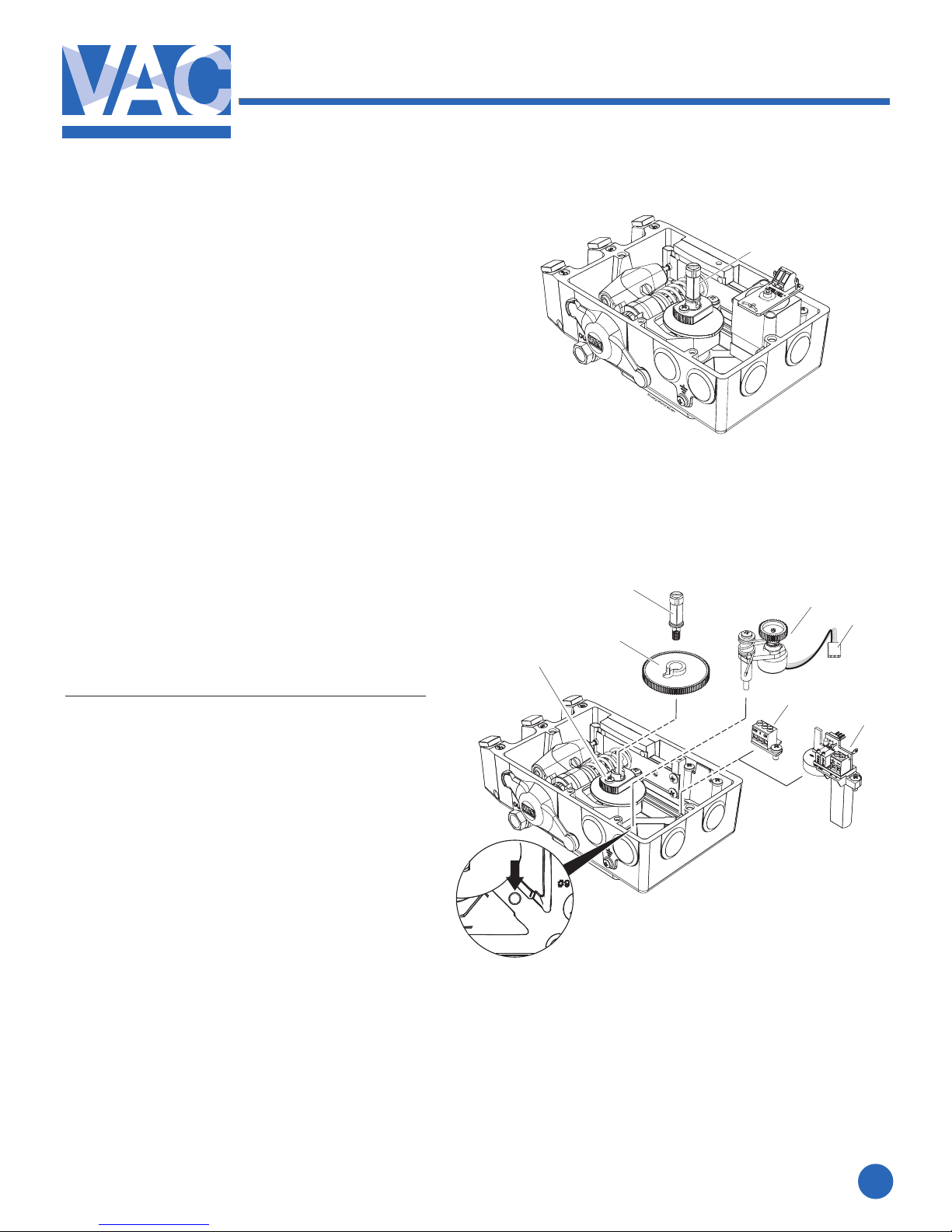
1.1 Principle of operation
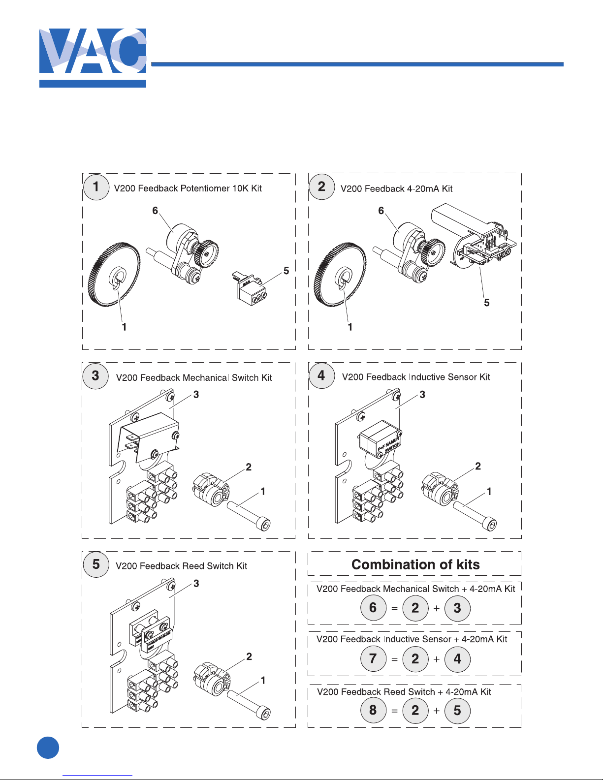
The V200 feedback options allows for accurate
positionfeedback,whereon-o(open/closed)
indication(switches)orcontinuous4-20mA
transmission(orsimplepotentiometer)isrequired.
Anyfeedbackmodulecanbefactoryoreldinstalled
inside the V200 positioner housing with no special
parts or mounting brackets. This creates a very
compact and simple package that is completely
sealed.
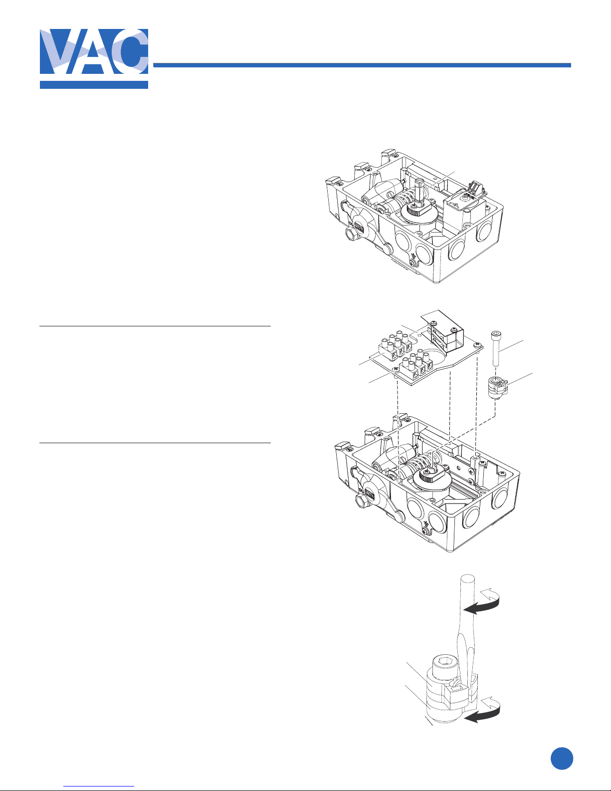
The various feedback options are connected to the
positionermaindriveshaft(1)whichisconnectedto
the actuator shaft via the positioner spindle, assisting
inamoredirectandaccurateactuator/valvemonitoring.
A position change moves the V200 spindle and switch
cam(2)foron-o(oropen/closed)indication.
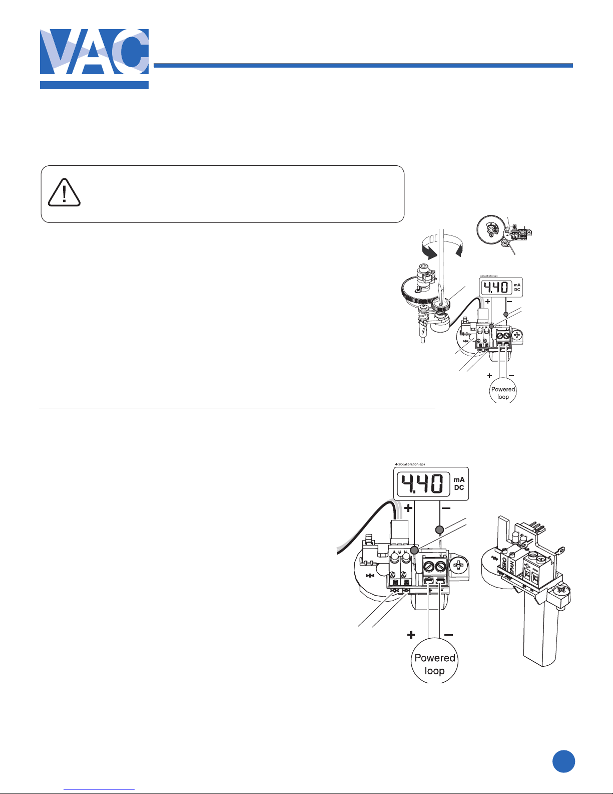
The4-20mApositiontransmittermkII(3)respondsto
changesproportionallyintheactuator/valvepackage.
It is recommended that the V200 positioner be
calibrated before installing feedback options.
CAUTION:
Beware of moving parts
when positioner is operated!
1.3 Safety instruction
CAUTION: Beware of parts with live voltage!
A voltage, which is normally not dangerous, is supplied to the positioner. Avoid touch-
ing live parts and bare wires as well as short circuiting live parts and the housing.
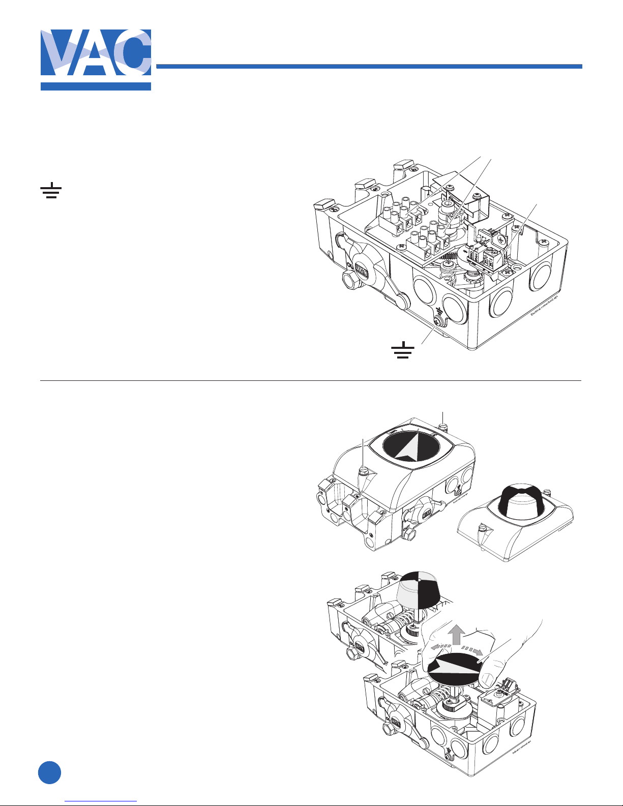
1.2 Product identication
TheV200identicationtags,Serialnumbertag(1),product-
modeltag(2)andfeedbackoptiontag(3),areplacedasshown.
The product model tag contains information on control signal,
maximum working pressure and temperature ranges.
Other information can be shown depending on the model.
Not for use in Hazardous locations.
Feedback options described in this manual
are for for General purpose only.
1
3
2

92077r14
www.vac.se
V200 POSITIONER
4
2. FEEDBACK INSTALLATION
2.1 Connections
– Grounding point
1. – Terminal block, switches
2 X 3 Connections
MaximumcablesizeAWG11(4mm2)
2. – Terminal block, Position Transmitter
MaximumcablesizeAWG13(2.5mm2)
1
1
2.2 Front cover and indicator
2.2.1 Removing the front cover
Loosenthetwoscrews(1)and
remove the front cover.
2.2.2 Removing the indicator
Pulltheindicator(2)straightup,itisafrictiont.
Important Note!
Note the indicator’s position so it
can be installed in the same position.
Installing the indicator
Install the indicator in place over the drive
shaft and press it straight down.
Be sure to press the indicator completely down
so that it does not interfere with the indicator
cover(clearcover).
Turn the indicator to the proper display
position.
2
1
2

92077r14
V200 POSITIONER
www.vacaccessories.com
5
2.3 4-20mA transmitter installation
2.3.1 Gearwheel installation
1. Remove the front cover and indicator
ontheV200positioner.(seepage4)
2.RemoveIndicatorscrew(1).
3.Installthegearwheel(2)sothatitalignsover
thecamlockingnutscrew(3).
4. Secure the gearwheel with the
Indicatorscrew(1).
2.3.2 Potentiometer installation
1.Installthepotentiometermodule(4)in
the designed section of the unit as
shown. Tighten the screw that secures
the pot arm and spring.
The pot gearwheel should be aligned
and secured to the larger gearwheel.
2.Installthepotentiometerboard(5)orthe
4-20mAtransmittermodule(6)intothe
designed position and tighten the respective
screws.
3. When used for the 4-20mA feedback, secure
thepotentiometerconnector(7)tothe
transmitter(6).Forpotentiometeruseonly,
theconnector(7)willattachtotheterminal
block(5)andbeusedwithanexternalposition
transmitter.
1
4
3
2
1
5
6
7

92077r14
www.vac.se
V200 POSITIONER
6
2.3.3 4-20mA transmitter setup
1. Determine the direction for
increasingmAoutput.Direct(CCW)
orReverse(CW).
2. The direction of rotation is simply
determined by watching the positioner
driveshaft(1).
3. CCW rotation: the potentiometer lead
connector(2)ttedwiththeBlackorBlue
colored lead facing to the left.
4. CW rotation: the potentiometer lead
connector(2)ttedwiththeBlackorBlue
colored lead facing to the right.
The position transmitter can be calibrated in a
range from 25° up to 115°.
25°-70°withJumper(3).
70°-115°noJumper(3).
The Position Transmitter is
shipped for direct (CCW)
turning, range 0-90°
2.3.4 Connecting the control signal
1. Connect the signal cable to the proper
poleontheterminalblock(1).
MaximumcablesizeAWG13(2.5mm2)1
1
2
2
3

92077r14
V200 POSITIONER
www.vacaccessories.com
7
1. Power up the current loop.
2.Connectalowohmicamperemeteroverthetestpoints(5).
3.Setthevalve/actuatortotheclosed/zeroposition(4mA).
4.Turnthefeedbackpotentiometershaft(6)with
a screw driver until you read 3.7 - 3.9 mA on the meter.
5.Adjustthetrimpotentiometer(7)markedzero
so that the meter reads 4mA.
6.Setthevalve/actuatortotheopenposition(20mA).
7.Adjustthetrimpotentiometer(8)marked
span until the meter reads 20mA.
8.Re-checkthezeroposition(4mA)and
makeneadjustmentsifnecessary.
A very basic calibration can be accomplished
without a meter, using the two LED’s.
Red LED lights up below 3.9mA, Green LED lights up above 20.1mA.
2.3.5 4-20mA transmitter Calibration
Make sure V200E/P has rst been properly calibrated!
Pot adjustment.eps
5
6
6
6
5
8
7
7 8

92077r14
www.vac.se
V200 POSITIONER
8
NOTE: Make sure V200E/P has rst been properly calibrated!
1.TurntheZERO-pot(2)morethan22turnscounterclockwise.
2.TurntheZERO-pot(2)5-6turnsclockwise.
3.TurntheSPAN-pot(3)morethan22turnscounterclockwise.
4.TurntheSPAN-pot(3)10-12turnsclockwise.
5.TurntheFEEDBACK-pot(1)until3.7-3.9mAisachieved.
6.AdjusttheZERO-pot(2)clockwiseto4mA.
7. Open the valve.
8.AdjusttheSPAN-pot(3)to20mA.
9. Close the valve.
10.Repeat(steps6-9)untiltheunitisproperlyset.
If you are unable to properly zero and span the feedback, the potentiometers
could be out of factory settings. In order to get back to factory settings please
follow the steps 1-8 below.
2.3.6 Trouble shooting - Reset and Calibration

92077r14
V200 POSITIONER
www.vacaccessories.com
9
2.4 Switch option Installation
2.4.1 Switch and cam installation
1. Remove the front cover and indicator
ontheV200positioner.(seepage4)
2.RemovetheIndicatorscrew(1).
3.Installtheswitchcamassembly(2)inthe
positioner drive slot and secure the cams with
screw(3).Installtheswitchmodule(4)and
tightenthethreescrews(5).
2.4.2 Electrical installation
Connectyourcontrolsystem/equipmentcables
totheterminalblocks(6)
MaximumcablesizeAWG11(4mm2)
2.4.3 Switch calibration
The switch activating points can be adjusted by
turningthefrictionloadedcams(7,8)usingascrew-
driver in the slots on the cams.
1.Withameter,settherstcamtoeithernormally
open(NO)ornormallyclosed(NC)atitsdesired
position.
2.Strokethevalve/actuatortothedesired
position for the second switch and adjust
the second cam.
3. Double check the two activation points.
NOTE: Use a non magnetic screwdriver when
adjusting reed switch cams!
3
1
8
7
6
4
5
2

92077r14
www.vac.se
V200 POSITIONER
10
3.1 Exploded drawing Feedback options
3. SPARE PARTS

92077r14
V200 POSITIONER
www.vacaccessories.com
11
3.2 Spare parts list Feedback options
Item Description Material Part no Qty
1.......V200 Feedback Potentiometer 10K Kit.........................93006.............. 1
(1 .......V200 Feedback Potentiometer 5K Kit...........................93028.............. 1)
(1 .......V200 Feedback Potentiometer 1K Kit...........................93047.............. 1)
1 ......Gearwheel 100-M0,5.............. Plastic <PA>..................90116.............. 1
5 ......Terminal Block, Potentiometer ......................................91015.............. 1
.......- Screw ISO 7045 MRX4x8-4.Stainless Steel ..............7045040804.... 1
6 ......Potentiometer Module 10K............................................93010.............. 1
(6......PotentiometerModule5K(Optional).............................93030.............. 1)
(6......PotentiometerModule1K(Optional).............................93031.............. 1)
.......- Pot Arm mkII ........................Zink ...............................90097.............. 1
.......- Potentiometer 6186 R10K L1,0...................................6186R10K....... 1
.......-Potentiometer6186R5KL1,0(Optional)....................6186R5K......... 1
.......-Potentiometer6186R1KL1,0(Optional)....................6186R1K......... 1
.......- Gearwheel 40-M0,5 .............Plastic <PA>..................90115.............. 1
.......- Tube spacer gear wheel.......Plastic <PA>..................90119.............. 1
.......- Circlip Gearwheel.................Stainless Steel ..............90067.............. 1
.......- Pot Spring coil......................Stainless Steel ..............90184.............. 1
.......- Shaft mkII Pot Arm............... Stainless Steel ..............90123.............. 1
.......- Screw ISO 7045 MRX4x50.. Stainless Steel ..............7045045050.... 1
.......- Washer ISO 7089-4 .............Stainless Steel ..............70894.............. 1
.......- Flat cable with connector ..... Plastic, brass, rubber ....92114.............. 1
2.......V200 Feedback 4-20mA Kit ..........................................93007.............. 1
1 ......Gearwheel 100-M0,5.............. Plastic <PA>..................90116.............. 1
5 ......4-20 mA module mkII ....................................................93123.............. 1
.......- Screw ISO 7045 MRX4x8-4.Stainless Steel ..............7045040804.... 1
6 ......Potentiometer Module 10K............................................93010.............. 1
.......- Pot Arm mkII ........................Zink ...............................90097.............. 1
.......- Potentiometer 6186 R10K L1,0...................................6186R10K....... 1
.......- Gearwheel 40-M0,5 .............Plastic <PA>..................90115.............. 1
.......- Tube spacer gear wheel.......Plastic <PA>..................90119.............. 1
.......- Circlip Gearwheel.................Stainless Steel ..............90067.............. 1
.......- Pot Spring coil......................Stainless Steel ..............90184.............. 1
.......- Shaft mkII Pot Arm............... Stainless Steel ..............90123.............. 1
.......- Screw ISO 7045 MRX4x50.. Stainless Steel ..............7045045050.... 1
.......- Washer ISO 7089-4 .............Stainless Steel ..............70894.............. 1
.......- Flat cable with connector ..... Plastic, brass, rubber ....92114.............. 1
3.......V200 Feedback Mechanical Switch Kit.........................93004.............. 1
1 ......Screw ISO 4762 M6x35 ......... Stainless Steel ..............4762063535.... 1
2 ......Switch Cam Module Mech ............................................93020.............. 1
.......- Switch Shaft.........................Zink ...............................90155.............. 1
.......- Switch Cam mkII.................. Zink ...............................90157.............. 2
.......- Switch Cam Clip mkII...........Stainless Steel ..............90158.............. 2
3 ......Switch Module Mechanical Switch ................................93023.............. 1
.......- Switch Plate .........................Aluminum, Anodized .....90118.............. 1
.......- Micro Switch V3 Camden...........................................CMNS 2020D . 2
.......- Protection Plate V3 ..............Plastic <PA>..................90086.............. 1
.......- Terminal block, 3 terminals. ........................................92064.............. 2
.......- Spacer DRN 3260x7.5........ Plastic <PA>..................3260075.......... 2
.......- Screw ISO 7045 MRX3x12.. Steel Zinc plated ...........7045031212.... 2
.......- Screw ISO 7045 MRX3x20.. Steel Zinc plated ...........7045032020.... 2
.......- Screw ISO 7045 MRX3x25.. Steel Zinc plated ...........7045032525.... 2
.......- Screw ISO 7045 MRX4x8-4.Stainless Steel ..............7045040804.... 3
.......- Washer ISO 7093-3 .............Stainless Steel ..............709303............ 2
.......- Cable Blue AWG 16 L = 8”..........................................92066.............. 2
.......- Cable Black AWG 16 L= 8” .........................................92067.............. 2
.......- Cable Brown AWG 16 L= 8”........................................92068.............. 2
Item Description Material Part no Qty
4.......V200 Feedback Inductive Sensor Kit............................93014.............. 1
1 ......Screw ISO 4762 M6x35 ......... Stainless Steel ..............4762063535.... 1
2 ......Switch Cam Module Inductive Sensor ..........................93022.............. 1
.......- Switch Shaft.........................Zink ...............................90155.............. 1
.......- Switch Cam mkII.................. Zink ...............................90157.............. 2
.......- Switch Cam Clip mkII...........Stainless Steel ..............90158.............. 2
.......- Steel Pin 4x2........................Steel...................................................... 2
3 ......SwitchModuleInductiveSensor(NAMUR) ..................93025.............. 1
.......- Switch Plate .........................Aluminum, Anodized .....90118.............. 1
.......-InductiveSensorNJ2-V3-N(NAMUR)........................NJ2-V3_N ....... 2
.......- Terminal Block, 3 Terminals ........................................92064.............. 2
.......- Spacer DRN 3260x7.5........ Plastic <PA>..................3260075.......... 2
.......- Screw ISO 7045 MRX3x12.. Steel Zinc plated ...........7045031212.... 2
.......- Screw ISO 7045 MRX3x20.. Steel Zinc plated ...........7045032020.... 2
.......- Screw ISO 7045 MRX3x25.. Steel Zinc plated ...........7045032525.... 2
.......- Screw ISO 7045 MRX4x8-4.Stainless Steel ..............7045040804.... 3
5.......V200 Feedback Reed Switch Kit...................................93005.............. 1
1 ......Screw ISO 4762 M6x35 ......... Stainless Steel ..............4762063535.... 1
2 ......Switch Cam Module Reed.............................................93021.............. 1
.......- Switch Shaft.........................Zink ...............................90155.............. 1
.......- Switch Cam mkII.................. Zink ...............................90157.............. 2
.......- Switch Cam Clip mkII...........Stainless Steel ..............90158.............. 2
.......- Magnet Neodym Ø4x2.........Neodym.........................43-0940-10 ..... 2
3 ......Switch Module Reed Switch..........................................93024.............. 1
.......- Switch Plate .........................Aluminum, Anodized .....90118.............. 1
.......- Reed Switch Hamlin....................................................59145 3S02A.. 2
.......- Spacer DRN 3260x7.5.........Plastic <PA>..................3260075.......... 2
.......- Spacer DRM 3260x2............Brass Ni plated..............326002............ 2
.......- Spacer DRN 3260x6............Brass Ni plated..............326006............ 2
.......- Terminal Block, 3 Terminals ........................................92064.............. 2
.......- Screw ISO 7045 MRX3x12.. Steel Zinc plated ...........7045031212.... 2
.......- Screw ISO 7045 MRX3x20.. Steel Zinc plated ...........7045032020.... 4
.......- Screw ISO 7045 MRX4x8-4.Stainless Steel ..............7045040804.... 3
.......- Washer ISO 7093-3 ............. Stainless Steel ..............709303............ 2
6.......V200 Feedback Mech+4-20mA Kit ...............................93011.............. 1
3......- V200 Feedback Mechanical Switch Kit.......................93004.............. 1
2......- V200 Feedback 4-20mA Kit ........................................93007.............. 1
7.......V200 Feedback Inductive Sensor +4-20mA Kit ............93015.............. 1
4......- V200 Feedback Inductive Sensor Kit..........................93014.............. 1
2......- V200 Feedback 4-20mA Kit ........................................93007.............. 1
8.......V200 Feedback Reed+4-20mA Kit................................93012.............. 1
5......- V200 Feedback Reed Switch Kit ................................93005.............. 1
2......- V200 Feedback 4-20mA Kit ........................................93007.............. 1

92077r14
www.vac.se
V200 POSITIONER
12
4. SPECIFICATIONS
4.1 Specications feedback options
Mechanical Switch module
Type:SPDT,V3(CamdenCMNS2020D)
Maximum load:
Resistive (Inductive) Voltage
10A (3)A 250 VAC
Reed Switch module
Type:SPDT-CO,FormC(Hamlin59145-3S02A)
Contact rating: max 3W
Voltage switching: max 175 VDC
Voltage breakdown: min 200 VDC
Current switching max 0.25 A
Current carry max 1.5 A
Contact resistance: 0.2 Ohm
Contact capacitance: 0.3 pF
Mechanical and electrical life: Over 100 million operations.
Inductive Sensors (NAMUR) module
Type:NAMUR2-wire,V3(P+FNJ2-V3-N)
Power supply: 5-25 VDC, 2-wire
Outputsignal: Targetabsent(o)>3mA(15mAmax.)
Targetpresent(on)<1mA
Hysteresis: 3-15%(5%typical)
Repeatability: <.01mm
Operatingtemperature: -14to+212°F(-10to+100°C)
4-20mA Position Transmitter module
Voltage supply: 7-30 VDC
Output: 4-20mA, 2 wire
Loop Impedance: max 850 Ohm @ 24 VDC
Linearity error: <1.2%
Hysteresis: <0.2%
Temperaturesensitivity: <0.1%/10°F(5.5°C)
Potentiometer module
Output: 10kOhm(5kOhmor1kOhmoptional)
Resistive element: Conductive plastic
Powerrating: 1W@158°F(70°C)
Linearity error: <1%
Resolution: Innity


Other manuals for V200 POSITIONER
3
Table of contents
Other VAC Valve Positioner manuals
Popular Valve Positioner manuals by other brands

Proval
Proval A236 Series Installation, operation and maintenance manual

cascade corporation
cascade corporation 55K installation instructions

Zimmer
Zimmer MK series Assembly instructions

SMAR
SMAR FY302 Operation, maintenance and instructions manual

halstrup-walcher
halstrup-walcher PS*3**SE series instruction manual

Pepperl+Fuchs
Pepperl+Fuchs PCV F200-B17-V1D Series manual