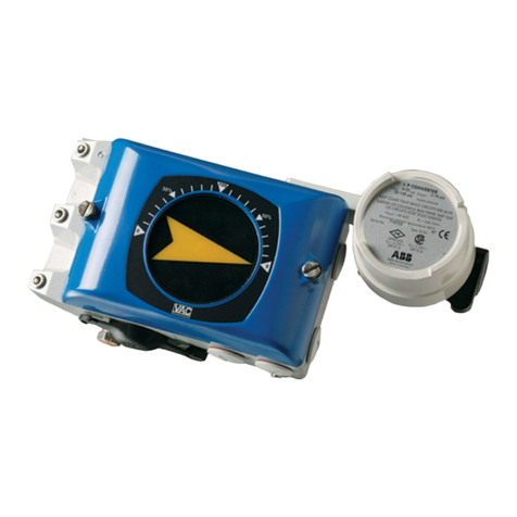
VAC V200 POSITIONER Use and care manual
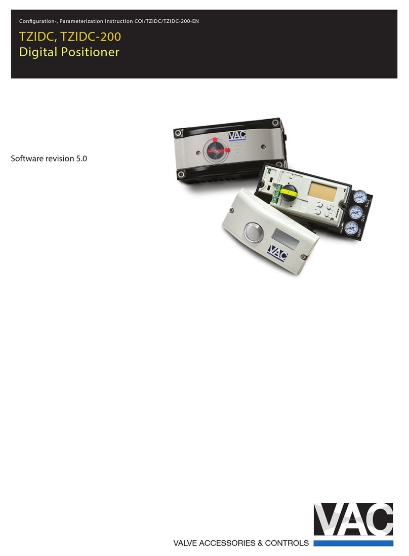
Other VAC Valve Positioner manuals
Popular Valve Positioner manuals by other brands

Parker
Parker MX80L series product manual

Westlock
Westlock Quantum 2800 Installation & operating instructions

Samson
Samson 3730-0 Mounting and operating instructions

Samson
Samson TROVIS 3730-3 Mounting and operating instructions

ESCO Technologies
ESCO Technologies ETS LINDGREN 2302-001 user manual

SMC Networks
SMC Networks IP8000 manual

Samson
Samson FOUNDATION 3730-5 Mounting and operating instructions

Samson
Samson TROVIS SAFE 3731-3 Mounting and operating instructions

Flowserve
Flowserve Logix 3400MD User instructions

halstrup-walcher
halstrup-walcher HIPERDRIVE instruction manual

ABB
ABB TZIDC Commissioning instructions

Samson
Samson FOUNDATION 3730-5 Mounting and operating instructions


