Vahle MKHF User manual

Montageanleitung - Wartung
Sicherheitsscheifleitungen
MKHF - MKHS
Mounting instructions - Maintenance
Enclosed conductor systems
MKHF - MKHS
MKHF_MKHS_FN_Komplett MKLD 07.07.2011 11:46 Seite 1

Table of content
1 Information on the Documentation 4
1.1 Additional documents 4
1.2 Symbols used 4
2 Safety instructions 5
2.1 Personnel qualifications 5
2.2 General safety
instructions 5
3 Transport and storage 5
4 General installation drawing 6
5 Installation of powerails 8
5.1 Mounting of support elements 9
5.2 Installation of the powerails 9
5.3 Alignment of the powerails 10
5.4 Creating conductor systems
connections 10
5.4.1Spring-loaded plug-in connector 11
5.4.2 Bolted joints 12
5.5 Mount the joint caps 14
5.6 Mounting the end caps 14
6 Mounting the power feeds 14
6.1 Tightening torques of
the connecting cables 14
6.2 Connect end feed,
40 - 63 A 14
6.3 Connecting the line feed 15
7 Mounting the current collectors 16
7.1 Inserting the current collectors 16
7.2 Electrical and
mechanical installation 16
8 Mounting special components 17
8.1 Transfer guides 17
8.2 Transfer funnel 19
8.3 Anti-condensation section 20
8.4 Expansion joint section 20
8.5 Heating 22
8.5.1 General 22
8.5.2 Installation guidelines 22
8.5.3 Simultaneous installation of the
sections and heating cables 23
8.5.4 Pulling in the heating cables into
premounted installations 24
8.5.5 Subsequent pulling in of
heating cables 25
8.5.6 Replacing a section after the heating
cables have been installed 25
8.5.7 Repairing a defective
heating cables 26
Inhaltsverzeichnis
1 Hinweise zur Dokumentation 4
1.1 Mitgeltende Unterlagen 4
1.2 Verwendete Symbole 4
2 Sicherheitshinweise 5
2.1 Qualifikation des Personals 5
2.2 Grundlegende
Sicherheitshinweise 5
3 Transport und Lagerung 5
4 Allgemeiner Verlegungsplan 6
5 Schleifleitungen montieren 8
5.1 Halteeisen anbringen 9
5.2 Schleifleitung aufhängen 9
5.3 Schleifleitung ausrichten 10
5.4 Stromschienenverbindungen
herstellen 10
5.4.1 Federsteckverbinder 11
5.4.2 Schraubverbinder 12
5.5 Stoßabdeckkappen montieren 14
5.6 Endkappen montieren 14
6 Einspeisungen montieren 14
6.1 Anziehdrehmomente
der Anschlussleitung 14
6.2 Kopfeinspeisung anschließen,
40 - 63 A 14
6.3 Streckeneinspeisung anschließen 15
7 Stromabnehmer montieren 16
7.1 Stromabnehmer einsetzen 16
7.2 Elektrische und
mechanische Installation 16
8 Sonderkomponenten montieren 17
8.1 Überleitungseinführungen 17
8.2 Einführungstrichter 19
8.3 Belüftungsteilstück 20
8.4 Dehnungsteilstück 20
8.5 Beheizung 22
8.5.1 Allgemeines 22
8.5.2 Montagehinweise 22
8.5.3 Gleichzeitige Montage der
Teilstücke und Heizkabel 23
8.5.4 Heizkabel an vormontierten
Anlagen einziehen 24
8.5.5 Nachträgliches Einziehen von
Heizkabeln 25
8.5.6 Austausch eines Teilstücks bei
montierten Heizkabeln 25
8.5.7 Reparatur eines defekten
Heizkabels 26
2
MKHF - MKHS
Montageanleitung •Mounting instructions
MKHF_MKHS_FN_Komplett MKLD 07.07.2011 11:46 Seite 2

3
8.5.8 Verlegung im Anschlusskasten 26
8.5.9 Netzanschluss installieren 27
8.5.10 Schaltbilder 28
8.6 Dichtlippe 28
8.7 Ausbauteilstück 30
9 Inbetriebnahme 31
10 Wartung 32
10.1 Schleifleitung 32
10.2 Stromabnehmer 33
8.5.8 Installation in the terminal box 26
8.5.9 Installing the electricsupply 27
8.5.10 Circuit diagrams 28
8.6 Sealing strip 28
8.7 Extension section 30
9 Commissioning 31
10 Maintenance 32
10.1 Conductor systems 32
10.2 Current collector 33
MKHF - MKHS
Montageanleitung •Mounting instructions
MKHF_MKHS_FN_Komplett MKLD 07.07.2011 11:46 Seite 3

1 Hinweise zur Dokumentation
1.1 Mitgeltende Unterlagen
Diese Montageanleitung sowie alle mitgel-
tenden Unterlagen sind Teil des Produktes.
Sie müssen dem Anlagenbetreiber ausge-
händigt werden. Dieser übernimmt die Auf-
bewahrung, damit die Unterlagen bei Be-
darf zur Verfügung stehen.
1.2 Verwendete Symbole
Beachten Sie folgende Sicherheitshinweise
und sonstige Hinweise in der Anleitung.
Folgende Benennungen und Zeichen
werden in dieser Anleitung für beson-
ders wichtige Angaben benutzt:
4Symbol für eine Handlungsanwei-
sung:
Der Pfeil zeigt an, dass Sie eine Hand-
lung durchführen sollen.
BLebensgefahr durch Strom-
schlag!
Hier finden Sie Hinweise auf
Situationen, bei denen die
Gefahr eines Stromschlags be-
stehen kann, und wie Sie diese
Gefährdung vermeiden können.
aGefahr!
Unmittelbare Gefahr für Leib
und Leben! Hier finden Sie
Hinweise auf Situationen, bei
denen eine unmittelbare Perso-
nengefährdung besteht, und
wie Sie diese Gefährdung ver-
meiden können.
SAchtung!
Mögliche Gefahr für Produkt
und Umwelt! Hier finden Sie
Hinweise auf Situationen, bei
denen Stromschienen oder
andere Anbauteile beschädigt
oder zerstört werden können,
und wie Sie diese Gefährdung
vermeiden können.
HHier erhalten Sie ergänzende
Hinweise.
1 Information on the
Documentation
1.1 Additional documents
These mounting instructions and all addi-
tionally applicable documents are part of
the product. They must be handed over to
the plant operator. He is responsible for
keeping the documents so that they are
available for reference as required.
1.2 Symbols used
Please observe all safety instructions
and other information in this manual.
The following denominations and sym-
bols are used in this manual for particu-
larly important indications:
4Symbol for instructions regarding
action:
This arrow indicates that you must take
action.
BDanger to life by electric
shock!
Here, you will find information
on situations in which may
bring about the risk of electric
shock, and on how to avoid
this potential hazard.
aDanger!
Immediate danger to life and
limbs! Here you will find informa-
tion on situations in which the
immediate risk of danger to
persons may arise, and on how
to avoid this potential hazard.
SAttention!
Potential danger to the product
and the environment! Here you
will find information about si-
tuations which may result in
damage to the conductor rails
or other parts of the assembly,
and on how to avoid this
potential hazard.
HHere you are provided with
additional information.
4
MKHF - MKHS
Montageanleitung •Mounting instructions
MKHF_MKHS_FN_Komplett MKLD 07.07.2011 11:46 Seite 4

2 Safety instructions
2.1 Personnel qualifications
Assembly, installation and maintenance
work may only be carried out by trained
technical personnel.
2.2 General safety instructions
The mounting instructions contain infor-
mation which must be observed for your
personal safety and for the avoidance of
damage to the equipment.
aRead the assembly instructions!
Observe the safety instructions!
Carefully read the mounting and
safety instructions before instal-
lation and exactly adhere to the
instructions contained therein.
BDanger of electric
shock!
Before starting the installation
work it is mandatory that you
disconnect the plant from the
mains! Danger of electric shock if
the equipment is incorrectly
connected. Always disconnect
the power supply before instal-
ling connections and secure
against being switched on again.
aDanger due to
improper use!
Do not make any changes to the
equipment, which are not descri-
bed in these or in the additionally
applicable documents.
3 Transport and storage
Information on transport and storage
– Observe the weight stated on the pak-
kage during transportand storage of
the conductor rails.
– Always store the conductor rails on an
even surface.
– The temperature during transport and
storage must not exeed 60° C.
2 Sicherheitshinweise
2.1 Qualifikation des Personals
Montage, Installation und Wartung
dürfen nur durch ausgebildetes Fachper-
sonal erfolgen.
2.2 Grundlegende Sicherheitshinweise
Die Montageanleitung enthält Hinweise,
die Sie zu Ihrer persönlichen Sicherheit
sowie zur Vermeidung von Sachschäden
beachten müssen.
aMontageanleitung lesen!
Sicherheitshinweise beachten!
Montageanleitung und Sicher-
heitshinweise vor der Montage
sorgfältig lesen und alle darin
enthaltenen Anweisungen genau
befolgen.
BLebensgefahr durch Strom-
schlag!
Vor Beginn der Montagearbeiten
die Anlage unbedingt span-
nungsfrei schalten! Gefahr eines
Stromschlages bei fehlerhaftem
Anschluss des Geräts. Schalten
Sie vor der Installation von
Anschlüssen immer die Strom-
versorgung ab und sichern Sie
sie gegen Wiedereinschalten.
aGefahr durch unsachgemäße
Anwendung!
Nehmen Sie am Gerät keine
Veränderungen vor, die nicht in
dieser oder den mitgeltenden
Anleitungen beschrieben sind.
3 Transport und Lagerung
Hinweise zu Transport und Lagerung
– Beachten Sie beim Transport der
Stromschienen die Gewichtsangaben
auf der Verpackung.
– Lagern Sie die Stromschienen immer
auf einer ebenen Unterlage.
– Die Umgebungstemperatur bei Trans-
port und Lagerung darf 60° C nicht
überschreiten.
5
MKHF - MKHS
Montageanleitung •Mounting instructions
MKHF_MKHS_FN_Komplett MKLD 07.07.2011 11:46 Seite 5

4 General installation drawing
aRisk of pinching between
mobile and fixed
components!
You must ensure that the
arrangement of the conductor
system provides minimum
distances (0.5 m) between fi-
xed and mobile plant parts (i.e.
between conductor rail, collec-
tor trolleys and towing arms)
so as to avoid the risk of pin-
ching!
SRisk of damage!
Install incoming power supply
units near the mains connecti-
on of the building!
The mains connecting cables
may not restrict the free ex-
pansion and contraction of the
conductor systems!
aRisk of damage!
Observe the plant-specific
documentation!
The following installation drawings
provide an overview of the recom-
mended installation distances
between the plant components.
Please make sure to observe
the plant-specific documents,
in which contain the order-rela-
ted installation drawings illu-
strate the plant layout.
4 Allgemeiner Verlegungsplan
aGefahr durch Quetschen
zwischen bewegten und
festen Teilen!
Es muss sichergestellt werden,
dass durch die Anordnung von
Stromschienen und Schleiflei-
tungen und Stromabnehmern
und Mitnehmerarmen die Si-
cherheitsabstände von 0,5 m
zwischen
festen und beweglichen Anlage-
teilen zur Vermeidung von
Quetschgefahren nicht unter-
schritten werden!
SBeschädigungsgefahr!
Einspeisungen in der Nähe des
gebäudeseitigen Netzan-
schlusses einsetzen!
Die Netzanschlusskabel dürfen
die Ausdehnung der Schleiflei-
tung nicht behindern!
aBeschädigungsgefahr!
Anlagenspezifische Doku-
mentation beachten!
Die folgenden Verlegungspläne
geben einen Überblick über die
empfohlenen Aufhängeabstän-
de zwischen den Anlagenkom-
ponenten.
Beachten Sie unbedingt die
anlagenspezifischen Unterla-
gen, in denen die auftragsbe-
zogenen Verlegungspläne den
Anlagenaufbau abbilden.
6
MKHF - MKHS
Montageanleitung •Mounting instructions
MKHF_MKHS_FN_Komplett MKLD 07.07.2011 11:46 Seite 6

Symbole / Symbols
Schleifleitung
Powerail
Kranbahn
Runway
Stoßabdeckkappe
Joint cover
Festaufhängung
Fixpointhanger
Gleitaufhägung
Slidinghanger
Endkappe
Endcap
Kopfeinspeisung
Endfeed
Streckeneinspeisung
Line feed
HThe safety lip (1) or the identifi-
cation strips (2) are principally
mounted towards the runway
(G1).
HPosition feed set close to the
incoming power supply!
Connecting cables may not re-
strict the free expansion and
contraction of the powerail
system!
Please do only use the
current collector MSWA!
HDer Sicherheitssteg (1) bzw.
die Kennzeichnungsstreifen (2)
werden grundsätzlich zur Kran-
bahn montiert (G1).
HEinspeisung in der Nähe des
Netzanschlusses einsetzen!
Anschlusskabel dürfen die
Ausdehnung der Schleiflei-
tung nicht behindern!
Grundsätzlich darf bei der
Schleifleitung MKH F/S nur
der Stromabnehmer MSWA
eingesetzt werden!
250-500 mm
max. 125 m
4 m
max. 2000 mm / 1333 mm
250-500 mm
L
()
L
()
()
()
L
() ()
( ) Kennzeichnung Steuerleitung
( ) for control unit
G1
G2
250-500 mm 250-500 mm
max. 250 m
4 m
max. 125 m max. 125 m
X
max. 2000 mm / 1333 mm
250-500 mm
250-500 mm
max. 125 m
max. 125 m
4 m
max. 250 m
X
max. 2000 mm / 1333 mm
250-500 mm
250-500 mm
Anschlussleitung flexibel
Cable connection flexible
1) Kopfeinspeisung / End feed
2) Eine Streckeneinspeisung (L/2) / One line feed (L/2)
3) Zwei Streckeneinspeisungen (L/6) / Two line feeds (L/6)
Aufhängeabstände:
4Max. 2000 mm für Innen- und über-
dachte Aussenanlagen mit einer Um-
gebungstemperatur bis 35 °C.
4Max. 1333 mm für Aussenanlagen,
spez. Innenanlagen mit hohen Umge-
bungstemperaturen (>35-60 °C) und
Anlagen mit Beheizung.
Support distance:
4Max. 2000 mm for indoor- and roo-
fed outdoor systems with a ambient
temperature upto 35 °C.
4Max. 1333 mm for outdoor systems,
special indoor systems with high am-
bient temperatures (>35-60 °C) and
systems with heating.
Verlegungsbeispiele Installation drawing
7
MKHF - MKHS
Montageanleitung •Mounting instructions
MKHF_MKHS_FN_Komplett MKLD 07.07.2011 11:46 Seite 7

5 Schleifleitungen montieren
– Beachten Sie vor der Montage den
anlagenspezifischen Verlegungsplan
und die mitgeltende Anlagendokumen-
tation.
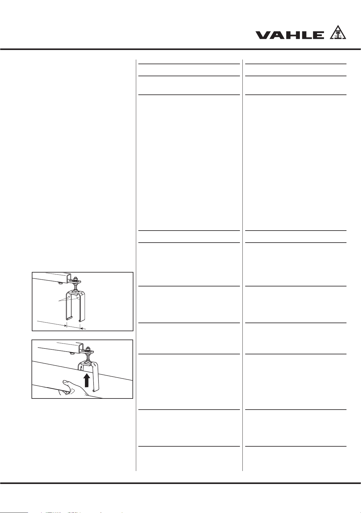
– Stromschienen so anordnen, dass der
Sicherheitssteg bzw. die Kennzeich-
nungsstreifen (1) zur Kranbahn hin aus-
gerichtet ist.
– Kurven- und Weichenstücke der
Schleifleitung, falls im anlagenspezifi-
schen Verlegungsplan vorgesehen, im-
mer zuerst montieren.
– Die Aufhängeabstände für Bögen und
Weichen sind im anlagenspezifischen
Verlegungsplan aufgeführt.
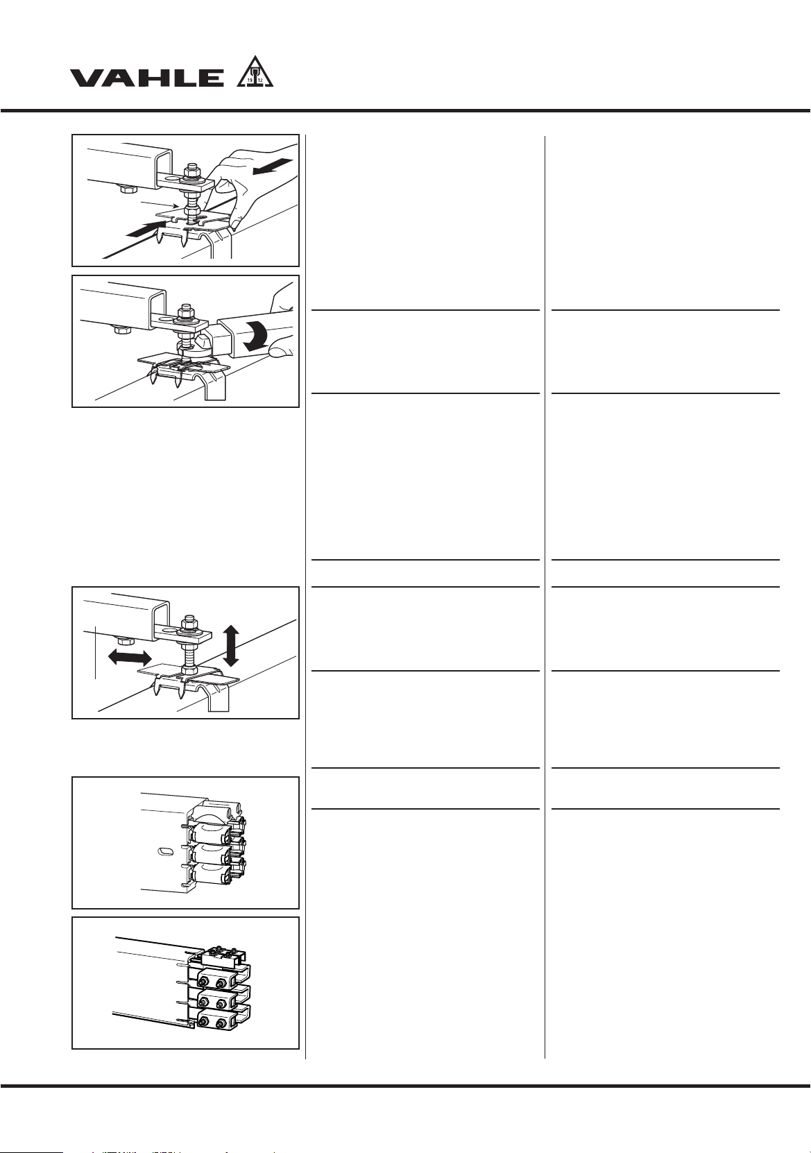
– Bei der Befestigung an den Konsolen
dürfen die Gleitaufhängungen nicht
verkanten, damit sich die Schleifleitung
frei bewegen kann.
Beachten Sie die folgenden Montage-
abstände für Stromschienen:
Aufhängeabstand:
– max. 2000 mm für Innenanlagen und
überdachte Außenanlagen mit einer
Umgebungstemperatur bis 35° C.
– max. 1333 mm für Außenanlagen,
spez. Innenanlagen mit hohen Umge-
bungstemperaturen (> 35-60° C) und
Anlagen mit Beheizung.
– Die letzte Aufhängung max. 500 mm
vom Teilstückende anbringen.
– Die Abstände zwischen Gleitaufhän-
gungen, Verstärkungsklammern, Ver-
bindungsmaterial, Endkappen, Einspei-
sungen usw. muss mindestens 250 mm
betragen, um die Materialausdehnung
nicht zu behindern (vgl. Kapitel 4 Allge-
meiner Verlegungsplan, S. 6).
– Schleifleitungsstöße durch Gleitauf-
hängungen mechanisch entlasten. Alle
Aufhängungen stoßentlastet mit einem
Abstand von 250 mm bis max. 500 mm
zwischen Stoß und Aufhängung mon-
tieren (vgl. Kapitel 4 Allgemeiner Verle-
gungsplan, S. 6).
HDie Schleifleitungen müssen
sich vom Festpunkt aus unge-
hindert ausdehnen können.
Zur Erleichterung der Montage
kann das erste Teilstück mit ei-
ner Festaufhängung festge-
setzt werden. Diese Aufhän-
gung muss nach Beendigung
der Montage als Gleitaufhän-
gung ausgeführt werden.
5 Installation of powerails
– Before installation, please observe the
plant-specific installation drawing and
the additionally applicable documenta-
tion.
– Arrange the conductor rails such that
the safety web (1) faces the machinery
track.
– Always install curves and switches of
the conductor systems first if planned in
the plant-specific installation drawing.
– The hanging distances for curves and
switches are listed in the plant-specific
installation drawing.
– During fixing to the support brackets,
the sliding hangers must not cant, so
that the conductor systems can move
freely.
Please observe the following mount-
ing distances for conductor rails:
Hanging distance:
– max. support distance 2000 mm for in-
door and roofed outdoor installations
with a ambient temperature upto 35° C.
– max. 1333 mm for outdoor installa-
tions, special indoor systems with high
ambient temperatures (> 35-60° C) and
systems with heating
– Attach the last hanger max. 500 mm
away from the end of the section.
– The distances between the sliding
hangers, the stiffener clamps, the con-
necting material, end caps, feed ele-
ments etc., must be at least 250 mm,
so as not to impair material expansion
(cf. chapter 4 General installation draw-
ing, page 6).
– Mechanically relieve conductor sys-
tems joints by means of sliding hang-
ers. Mount all hangers with relieved
joints with a distance of 250 mm to
max. 500 mm between joint and hanger
(cf. chapter 4 General installation draw-
ing page 6).
HFree expansion of the conductor
systems away from the
fixpoint must be possible.
Provisionally anchor the first
conductor systems section with
the two fixpoint hangers to facili-
tate the further mounting proce-
dure.The fixpoint hanger must be
replaced by a sliding hanger after
system installation has been
completed.
8
MKHF - MKHS
Montageanleitung •Mounting instructions
MKHF_MKHS_FN_Komplett MKLD 07.07.2011 11:46 Seite 8

5.1 Halteeisen anbringen
4Schraubkonsolen oder Winkeleisen
mit Langlöchern anbringen.
HFolgenden Montage-Abstände
beachten:
Aufhängeabstand max. 2000 mm
für Innenanlagen und überdachte
Aussenanlagen mit einer Umge-
bungstemperatur bis 35 °C.
Max. 1333 mm für Aussenanla-
gen, spez. Innenanlagen mit
hohen Umgebungstemperaturen
(>35-60 °C) und Anlagen mit Be-
heizung. Die erste und letzte Auf-
hängung ist mind. 250 mm und
max. 500 mm vom Teilstückende
anzuordnen. Der Abstand der
Gleitaufhängungen von dem Ver-
bindungsmaterial, den Endkap-
pen, Einspeisungen usw. muss
mindestens 250 mm bis max.
500 mm betragen, um die Aus-
dehnung nicht zu behindern (S2).
5.2 Schleifleitung aufhängen
Die beiliegenden Unterlegscheiben an
den Aufhängebolzen der Fest- und Gleit-
aufhängungen nur bei der Montage in
Langlöchern verwenden.
4Gleitaufhängungen an den Konsolen
befestigen (G3).
SDie Schenkel der Gleitaufhän-
gung müssen senkrecht nach
unten und mit einem Zwi-
schenmaß von < 51 mm sein
(bei Bedarf nachrichten) (G3).
4Schleifleitungen von unten in die
Gleitaufhängungen schieben (G4).
SDie Schleifleitungen müssen mit
den unteren Stegen in den zwei
U-förmigen Umgreifungen der
Gleitaufhängungen liegen.
Auf durchgehend gleiche
Anordnung der Kennzeich-
nungsstreifen und Sicher-
heitsstege achten (S1).
HDer Aufnahmebügel der Gleit-
aufhängung ist drehbar gela-
gert und stellt sich bei der
Montage in Längsrichtung zur
Schleifleitung ein.
5.1 Mounting support brackets
4Bolt EHK standard brackets or weld
steel angles with slotted holes.
HObserve the following installa-
tion distances:
Max. support distance 2000 mm
for indoor and roofed outdoor
installations with a ambient tem-
perature upto 35 °C).
Max. 1333 mm for outdoor in-
stallations, special indoor
systems with high ambient
temperatures (>35-60 °C) and
systems with heating. The first
and last hanger must be placed
at least 250 mm and no more
than 500 mm from the end of a
powerail section. The distance of
the sliding hangers from the joint
material, end caps, feed points,
etc. must measure at least
250 mm and up to 500 mm to
guarantee free expansion (S2).
5.2 Installation of powerail
Use the supplied washers at the support
bolts of the fixpoint and sliding hangers
only for installation in slotted holes.
4Attach the sliding hangers at the
brackets (G3).
SThe branches of the sliding
hanger must be vertical and
down with an intermediate
measure of < 50 mm (realign, if
necessary) (G3).
4Push the Powerails from the bottom
into the sliding hangers (G4).
SThe powerails must be located
in the two U-shaped webs of
the sliding hangers with the
two lower lips.
Ensure continuous uniform
arrangement of the identifi-
cation strips and safety lips
(S1).
HThe mounting brackets of the
sliding hanger is rotatable and
adjusts itself in longitudinal
direction to the powerail during
installation.
< 51 mm
< 90°
G3
G4
9
MKHF - MKHS
Montageanleitung •Mounting instructions
MKHF_MKHS_FN_Komplett MKLD 07.07.2011 11:46 Seite 9

Jede Gleitaufhängung kann zur Festauf-
hängung sowie jede Festaufhängung zur
Gleitaufhängung umgebaut werden.
4Dazu die oberhalb des Aufnahmebü-
gels liegende Mutter lösen (1) so weit,
bis ein Freiraum von etwa 10 mm ent-
steht (G5).
4Die beiden Festsetzerbleche von rechts
und links einschieben, so dass sich diese
ineinander verschachteln (G5).
4Sechskanntmuttern mit 5 - 7 Nm wie-
der anzeihen (G6).
SBei gerader Verlegung eine
Festaufhängung etwa in der
Mitte der Anlage oder nach
Verlegungsplan montieren
(
G2).
HDie Schleifleitung muss sich von
dem Festpunkt aus ungehindert
ausdehnen können. Zur Erleich-
terung der Montage kann das
erste Teilstück mit einer Festauf-
hängung festgesetzt werden.
Achtung! Diese Aufhängung
muss nach Beendigung der
Montage wieder zu einer Gleit-
aufhängung umgebaut werden.
5.3 Schleifleitung ausrichten
4Aufhängebolzen in dem Langloch der
Konsole seitlich verschieben (bei Ver-
wendung von Vahle EHK Konsolen
das Halteeisen verschieben). Höhe
mit den Muttern (1) einstellen (G7).
HDie Schleifleitung muss
genau fluchtend zur Kran-
bahn montiert werden ..
Auch die Stöße müssen
fluchten.
5.4 Stromschienenverbindungen
herstellen
Bei Schleifleitungen MKHF für 40 A, 63 A
und 100 A können Federsteckverbinder
verwendet werden (G8).
Bei Schleifleitungen MKHS für 140 A,
160 A und 200 A müssen Schraubverbinder
verwendet werden (G9).
An den rechten Enden der Kupferschie-
nen sind die Verbinder werkseitig vor-
montiert (G8, G9).
Die seitlichen und oberen Verbinder
unterscheiden sich in der Kupferschie-
nenbreite.
– Obere Verbinder: 11 mm breites Cu
mit grauen Isolierkappen
– Seitliche Verbinder:13 mm breites Cu
mit schwarzen Isolierkappen
Each sliding hanger can be converted to
a fix-point hanger and vice versa.
4For this purpose, loosen the nut
located above the mounting bracket
(1) until a clearance of approx.
10 mm is reached (G5).
4Insert the two fastener plates on the
left and the right until they interlock
(G5).
4Tighten the hexagonal nuts with
5 - 7 Nm (G6).
SIf you install a straight run,
install one fixpoint hanger
approximately at the center of
the system or according to the
layout plan
(G2
).
HFree expansion of the powerail
away from the fixpoint must be
possible. Provisionally anchor
the first powerail section with
two fixpoint hangers to facilitate
the further mounting procedure.
Caution! This fixpoint hanger
must be replaced by a sliding
hanger after system installation
has been completed.
5.3 Alignment of powerails
4Move support bolts of the console
sideways in the slotted hole (when
using Vahle EHK consoles move the
support bracket). Adjust the height
using the nuts (1) (G7).
HThe powerail must be installed
precisely aligned to the
runway.
Even the joints must be
aligned
5.4 Creating conductor systems
connections
In the case of MKHF powerails for 40 A,
63 A and 100 A, spring-loaded plug-in
connectors can be used (G8).
In the case of MKHS powerails for 140
A, 160 A and 200 A, bolted joints must be
used (G9).
The connectors are pre-mounted at
works at the right-hand ends of the cop-
per rails (G8, G9).
The side and top connectors differ in the
width of the copper rails
– Top connector: 11 mm wide
with grey isolating caps
– Side connector:13 mm wide
with black isolating caps
1
G5
G6
EHK
G7
10
MKHF - MKHS
Montageanleitung •Mounting instructions
G9
G8
MKHF_MKHS_FN_Komplett MKLD 07.07.2011 11:46 Seite 10

5.4.1 Federsteckverbinder
(nur bei MKHF)
4Gleitend aufgehängte Teilstücke zu-
einander schieben (G10).
4Kupferschienenenden einzeln 5-10 mm
in die Federsteckverbinder einführen
(G11).
4Beide Gehäuse so weit zusammen-
schieben, bis eine mechanisch feste
Verbindung entsteht (G12).
S
Achtung!
Elektrische Verbindung
Die Federsteckverbinder müs-
sen vollständig einrasten, um
die notwendige elektrische
Verbindung zu gewährleisten.
4Teilstücke nach außen ziehen, um die
Einrastung zu prüfen (G13).
4Übergang der Kupferschienenstöße
durch Sicht- und Tastkontrolle prüfen.
Der Übergang muss glatt, bündig und
ohne Grat sein, um eine Beschädi-
gung der Schleifkohlen des Stromab-
nehmers zu vermeiden. Max. Ab-
stand zwischen den Kupferschienen:
2 mm (G14).
4Stromabnehmer einsetzen (vgl. Kapi-
tel 7 Stromabnehmer montieren,
S. 16) und durch den Bereich fahren,
um Unregelmäßigkeiten festzustellen.
5.4.1 Spring-loaded plug-in connector
(only for MKHF)
4Push sections with sliding suspen-
sion together (G10).
4Insert the copper rail ends separately
5-10 mm into the spring-loaded plug-
in connectors (G11).
4Push both housings together until a
firm mechanical connection is
obtained (G12).
SCaution!
Electrical Connection
The plug-in-joints have to snap
in completely to ensure the
necessary electrical connection.
4Pull both sections out of the housings
apart a little bit to check if the connec-
tors are snapped in correctly (G13).
4Visually check the transition point of
the copper rail joints and also feel the
transition point with your fingers as a
check. The transition point must be
smooth, flush and have no burr so as
to avoid damage to the current collec-
tor’s carbon brushes. Max. distance
between the copper rails: 2 mm (G14).
4Insert the current collector (cf. chapter
7 Current Collectors, page 16) and
move through the area to detect irregu-
larities.
5-10 mm
G11
G12
G10
G13
G14
11
MKHF - MKHS
Montageanleitung •Mounting instructions
MKHF_MKHS_FN_Komplett MKLD 07.07.2011 11:46 Seite 11

Federsteckverbinder demontieren
Die seitlichen und oberen Federsteck-
verbinder der Stromschienen MKHF
haben unterschiedliche Bauformen. Zur
Demontage folgendermaßen vorgehen:
4Stoßabdeckkappe demontieren siehe
S. 12.
4Führungskappen der seitlichen Ver-
binder durch Spreizen der Verriege-
lungsnasen abziehen (G15).
4Führungskappen der oberen Verbin-
der durch Aufspreizen der Führungs-
kappe abziehen.
4Sicherungsbügel seitlich ausbauen
(G16).
4Federsteckverbinder von den Kupfer-
schienen abkippen (G17).
Die Montage der Federsteckverbinder
erfolgt in umgekehrter Reihenfolge.
5.4.2 Schraubverbinder
(nur bei MKHS)
HDie Schraubverbinder können
bei Schleifleitungen MKHS von
40-200 A eingesetzt werden.
4Gleitend aufgehängte Teilstücke zu-
einander schieben (G18).
4Kupferschienenenden einzeln 5-10 mm
in die Schraubverbinder einführen
(G19).
Dismantling the spring-loaded plug-in
connector
The side and top spring-loaded plug-in
connectors of the MKHF conductor rails
have different constructions. To disman-
tle, please proceed as follows:
4Dismantle the joint cap see page 12.
4Disassemble the black pvc caps by
pulling the two locking lugs apart
(G15).
4Remove the security spring sideways
(G16).
4Tilt away the joints from the copper
conductor (G17).
Mounting the spring-loaded plug-in con-
nectors is done in reverse order.
5.4.2 Bolted joints
(only for MKHS)
HThe bolted joints can be used
for MKHS powerails from
40-200 A
4Push sections with sliding suspension
together (G18).
4Insert the copper rail ends separately
5-10 mm into the bolted joints (G19).
G15
G16
G17
G18
5-10 mm
G19
12
MKHF - MKHS
Montageanleitung •Mounting instructions
MKHF_MKHS_FN_Komplett MKLD 07.07.2011 11:46 Seite 12

4Beide Gehäuseteilstücke soweit
zusammenschieben, bis eine mecha-
nische Verbindung entsteht (G20).
S
Achtung!
Elektrische Verbindung
Die Schraubverbinder müssen
vollständig einrasten, um die
notwendige elektrische Ver-
bindung zu gewährleisten.
4Sitz der Verbinder am Kupferschienen-
stoß prüfen durch Auseinanderziehen
und Zusammenschieben der Teilstük-
ke. Die Verriegelungsnasen der Verbin-
der müssen eingerastet sein.
4Muttern lösen. Gewindestifte (1) mit
einem 3 mm Innensechskantschlüs-
sel anziehen. Muttern kontern (2)
(G21).
SBeschädigungsgefahr!
Anziehdrehmomente für die
Schraubverbindungen beachten:
– Gewindestifte: 1,5 – 2 Nm
– Muttern: 5 Nm
4Übergang der Kupferschienenstöße
durch Sicht- und Tastkontrolle prüfen
(G22). Der Übergang muss glatt und
bündig sowie ohne Grat sein, um eine
Beschädigung der Schleifkohlen des
Stromabnehmers zu vermeiden. Max.
Abstand zwischen den Kupferschie-
nen: 2 mm.
4Stromabnehmer einsetzen (vgl.
Stromabnehmer montieren, S. 16)
und durch den Bereich fahren, um
Unregelmäßigkeiten festzustellen.
5.5 Stoßabdeckkappen montieren
4Stoßabdeckkappenhälften von unten
mittig auf die Verbindungsstelle auf-
setzen.
Die Noppen (2) der Kappen müssen in
die Langlöcher (1) des Schleifleitungs-
profils einrasten (G23).
Die U-förmigen Umgreifungen (3) der
Stoßabdeckkappen müssen an den
unteren Stegen der Schleifleitung einra-
sten (G24).
4Abdeckkappenhälften oben zusam-
mendrücken und hörbar einrasten.
HDie Stöße müssen horizontal
und vertikal fluchten.
4Push both parts of the housing togeth-
er until a firm mechanical connection
is obtained (G20).
SCaution!
Electrical Connection
The plug-in-joints have to snap
in completely to ensure the
necessary electrical connection
4Check the seat of the connectors at
the copper rail joint by pulling apart
and pushing together the sections.
The locking elements of all connec-
tors must be engaged..
4Loosen the nuts. Tighten the
setscrews (1) with a 3 mm Allen key.
Lock the nuts (2) (G21).
SRisk of damage!
Observe tightening torques for
the bolted joints:
– Setscrews: 1.5 – 2 Nm
– Nuts: 5 Nm
4Visually check the transition point of
the copper rail joints and also feel the
transition point with your fingers as a
check (G22). The transition point must
be smooth, flush and have no burr so
as to avoid damage to the current col-
lector’s carbon brushes. Max. dis-
tance between the copper rails: 2 mm.
4Insert the current collector (cf. chap-
ter Mounting the current collectors,
page 16) and move through the area
to detect irregularities.
5.5 Mount the joint caps
4Place both halves of the joint caps
onto the middle of the connecting
point from below.
The naps (2) of the caps must engage
into the slotted holes (1) of the conductor
systems profile (G23).
The U-shaped encompassing elements (3)
of the joint caps must engage in the bottom
webs of the conductor systems (G24).
4Press both halves of the joint caps
together and audibly engage.
HThe joints must be aligned ho-
rizontally and vertically.
G20
1.
2.
max. 5 Nm
max. 2 Nm
G21
G22
12
G23
3
click
click
G24
13
MKHF - MKHS
Montageanleitung •Mounting instructions
MKHF_MKHS_FN_Komplett MKLD 07.07.2011 11:46 Seite 13

Stoßabdeckkappe demontieren
4Die beiden Stoßabdeckkappenhälf-
ten mit einem Schlitzschraubendre-
her (7 mm breit) auseinanderhebeln.
Abdeckkappenhälften auseinander-
ziehen und abnehmen (G25).
5.6 Endkappen montieren
Endkappen müssen an allen Schleiflei-
tungsenden ohne Kopfeinspeisung an-
gebracht werden.
4Vormontierten Federsteckverbinder
bzw. Schraubverbinder an den
Schleifleitungsenden entfernen.
4Abschlusswinkel und Endkappenhälf-
ten auf das Schleifleitungsende
setzen (G26).
4Endkappenhälften oben zusammen-
drücken und hörbar einrasten (G27).
6 Einspeisungen montieren
Festaufhängung in direkter Nähe zur Ein-
speisung (max. 5 m) vorsehen oder nach
„Allgemeiner Verlegungsplan”, S. 6 mit
Gleitaufhängungen und flexiblem Kabel-
anschluss anbringen.
6.1 Anziehdrehmomente der
Anschlussleitungen
Schraubverbindungen der elektrischen
Anschlüsse mit den folgenden Anzieh-
drehmomenten festziehen:
– Sechskantschrauben M6:max. 2 Nm
– Sechskantschrauben M8: .max. 10 N
6.2 Kopfeinspeisung anschließen,
40 – 63 A
Die Kopfeinspeisung kann an das linke
oder rechte Ende der Schleifleitung
montiert werden.
Die Kopfeinspeisung ist ein Festpunkt für
die Kupferschienen am Gehäuse.
4Schieben Sie die Anschlussklemmen
(1) auf die Kupferschienenenden und
schrauben Sie die Gewindestifte (M6)
mit einem 3 mm Sechskantschlüssel
mit 2 Nm (2) auf den Kupferschienen
fest (G28).
Dismantling the joint cap
4Press open the two halves of the joint
caps with a slotted screwdriver
(7 mm wide). Pull the joint cap halves
apart and remove them (G25).
5.6 Mounting the end caps
End caps must be installed at all conduc-
tor systems ends without end feed.
4Remove pre-assembly spring-loaded
plug-in connectors and/or bolted
joints at the conductor systems ends.
4Place end bracket and end cap
halves onto the conductor systems
end (G26).
4Press both halves of the end caps
together and audibly engage (G27).
6 Mounting the power feeds
Provide fixpoint hangers in the immedi-
ate vicinity of the power feed (max. 5 m)
or attach acc. to “General installation
drawing” page 6 with sliding hangers and
flexible cable connection.
6.1 Tightening torques of the
connecting cables
Tighten the bolted joints of the electrical
connections with the following tightening
torques:
– Hex screw M6: max. 2 Nm
– Hex screw M8: max. 10 Nm
6.2 Connect end feed, 40 – 63 A
The end feed can be mounted to the left
or right end of the conductor systems.
The end feed is a fixed point for the cop-
per rails on the housing.
4Push the connecting terminals (1)
onto the copper ends and fix the
threaded pins (M6) with a 3 mm hexa-
gon wrench with 2 Nm (2) at the
copper rails (G28).
G25
G26
click
click
G27
1
2
x
max. 2 Nm
G28
14
MKHF - MKHS
Montageanleitung •Mounting instructions
MKHF_MKHS_FN_Komplett MKLD 07.07.2011 11:46 Seite 14

– for the lateral copper rails terminals
with dimension ,,x’’ = 16 mm
– for the top copper rails terminals with
dimension ,,x’’ = 14 mm
4Stick on the identification label (e. g.
L1, L2...) considering the safety web
on the conductor systems profile to
the left and right ends of the conduc-
tor systems.
4Mount the plastic bracket (1), the M
screw connection (2) for the main power
cable and if required the M screw con-
nection for the control cable (3) (G29)
Before screwing down the connecting
cables, please proceed as follows:
4Reduce connecting cables to 80 mm
individual strand length.
4Attach cable shoes.
4Thread connecting cables through
screwed cable connection.
BDanger of damage due to in
correct polarity!
Check the pole assignment of
the connecting cables to the
identification labels.
4Place the plastic brackets onto the
end of the housing.
4Screw the terminal lugs onto the
threaded pins in the following order:
Terminal lugs, serrated washers, hex
nuts (G30).
4Tighten the hex nuts with 5 Nm.
4Position cover cap and press together.
4Tighten the M screw connection until
the cable is sealed off.
6.3 Connecting the line feed
The section with the line feed can be
mounted anywhere between the sections
or acc. to the plant-specific installation
drawing.
4Unscrew the housing cover of the
feed and push it aside (G31).
Before screwing down the connecting
cables, please proceed as follows:
4Reduce connecting cables to approx.
220 mm individual strand length.
4Attach cable shoes.
4Guide the connecting cables through
the cable connection.
– für die seitlichen Kupferschienen
Klemmen mit Maß ,,x’’ = 16 mm
– für die oberen Kupferschienen
Klemmen mit Maß ,,x’’ = 14 mm
4Kennzeichnungsaufkleber (z. B. L1,
L2...) unter Beachtung des Sicher-
heitsstegs am Schleifleitungsprofil an
den linken und rechten Enden auf die
Schleifleitung aufkleben.
4Kunststoffwinkel (1), die M-Ver-
schraubung (2) für das Hauptstrom-
kabel und bei Bedarf die M-Ver-
schraubung für das Steuerkabel (3)
montieren (G29).
Vor dem Verschrauben der Anschluss-
leitungen wie folgt vorgehen:
4Anschlussleitungen auf 80 mm
Einzeladerlänge absetzen.
4Kabelschuhe anbringen.
4Anschlussleitungen durch Leitungs-
verschraubung führen.
BBeschädigungsgefahr durch
Verpolung!
Achten Sie auf die Polzuord-
nung der Anschlussleitungen zu
den Kennzeichnungsaufklebern.
4Kunststoffwinkel auf das Gehäuse-
ende stecken.
4Schrauben Sie die Kabelschuhe an die
Gewindewstifte in der Reihenfolge:
Kabelschuhe, Fächerscheiben,
Sechskantmuttern (G30).
4Ziehen Sie die Sechskantmuttern mit
5 Nm an.
4Abdeckkappe aufsetzen und zusam-
mendrücken.
4M-Verschraubungen so weit anziehen,
bis das Kabel abgedichtet ist.
6.3 Streckeneinspeisung anschließen
Das Teilstück mit der Streckeneinspeisung
kann an beliebiger Stelle oder nach anla-
genspezifischem Verlegungsplan zwischen
den Teilstücken montiert werden.
4Gehäuseabdeckung an der Ver-
schraubungsseite der Einspeisung
aufschrauben und zur Seite schieben
(G31).
Vor dem Verschrauben der Anschlusslei-
tungen wie folgt vorgehen:
4Anschlussleitungen auf ca. 220 mm
Einzeladerlänge absetzen.
4Kabelschuhe anbringen.
4Anschlussleitungen durch die M-Ver-
schraubung führen.
G29
4
3
L1
1
L2
max. 5 Nm
M6
G30
4
3
L1
L2
1
1
2
3
G31
15
MKHF - MKHS
Montageanleitung •Mounting instructions
MKHF_MKHS_FN_Komplett MKLD 07.07.2011 11:46 Seite 15

BBeschädigungsgefahr durch
Verpolung!
Achten Sie auf die Polzuord-
nung der Anschlussleitungen zu
den Kennzeichnungsaufklebern.
4Kabelschuhe mit Fächerscheiben
und M8 Sechskantschrauben an den
Klemmen festsetzen (G32).
SBeschädigungsgefahr!
Anziehdrehmoment für die
Schraubverbindung:
max. 10 Nm.
4M-Verschraubung so weit anziehen,
bis das Kabel abgedichtet ist.
4Gehäuse der Einspeisung zurück-
schieben und verschrauben.
7 Stromabnehmer montieren
BLebensgefahr durch Strom-
schlag!
Bevor Sie die elektrische Ver-
bindung herstellen, müssen
Sie die Anlage spannungslos
schalten!
7.1 Stromabnehmer einsetzen
4Stromabnehmer am Ende der
Schleifleitung oder im Ausbauteil-
stück (Standardzubehör, siehe Kapi-
tel 8.7 ,,Ausbauteilstück’’) einsetzen.
Durch den Sicherheitsanschlag (1) am
Stromabnehmer wird falsches Einsetzen
verhindert (G33).
7.2 Elektrische und mechanische
Installation
SBeschädigungsgefahr durch
Verpolung!
Achten Sie auf die Polzuordnung
des Stromabnehmers!
Grundsätzlich darf bei der Schleif-
leitung MKH nur der Stromabneh-
mer MSWA eingesetzt werden.
4Stromabnehmer an den Verbraucher
anschließen. Den freihängenden Teil
der Anschlusskabel mit einem mini-
malen Biegeradius von 10 x Leitungs-
durchmesser (D) verlegen (G34)
SBeschädigungsgefahr für die
Stromabnehmer!
Die Anschlusskabel dürfen die
Beweglichkeit des Stromabneh-
mers nicht behindern!
BDanger of damage in case of
incorrect polarity!
Check the pole assignment of
the connecting cables to the
identification labels.
4Screw the cable shoes with the ser-
rated lock washer and M8 hex srews
to the clamps (G32).
SDanger of damage!
Tightening torques for the screw
connection:
max. 10 Nm.
4Tighten the M screw connection until
the cable is sealed off.
4Push the feed housing back into
place and screw in.
7 Mounting the current
collectors
BDanger to life by electric
shock!
Before creating the electrical
connection you must discon-
nect the power supply to the
plant!
7.1 Inserting the current collectors
4Insert the current collectors at the
end of the conductor systems or in
the extension element (standard ac-
cessories, see chapter 8.7 “Extension
element“).
Incorrect installation is avoided due to
the safety stop (1) on the current collec-
tor (G33).
7.2 Electrical and mechanical
installation
SRisk of damage as the result
of incorrect polarity!
Observe the polarity of the
current collector!
Please do only use the
current collector MSWA!
4Connect the current collector to the
electrical load. Lay the freely sus-
pended section of the connecting ca-
ble with a minimum bending radius of
10 x conductor diameter (D) (G34).
SRisk of damage from the
current collector!
The connecting cables must not
restrict the movement of the
current collector!
1
L1
L2
G32
L
()
L
()
()
()
L
() ()
( ) Kennzeichnung Steuerleitung
( ) for control unit
G33
G34
16
MKHF - MKHS
Montageanleitung •Mounting instructions
MKHF_MKHS_FN_Komplett MKLD 07.07.2011 11:46 Seite 16

Schalter, Sicherungen und Kabel zur Ver-
drahtung sind kundenseitig bereitzustel-
len und zu montieren.
4Mechanische Verbindung zwischen
Stromabnehmer und Verbraucher
durch den Mitnehmer herstellen.
Es gibt eine Ausführung zur Montage an
einem Rohr mit Adapterblech oder
Quadrat-Hohlprofil (A) und zur Montage
an einer ebenen Fläche (B) (G35).
8 Sonderkomponenten
montieren
BBeschädigungsgefahr!
Anlagenspezifische Doku-
mentation beachten!
Beachten Sie unbedingt die
anlagenspezifischen Unterla-
gen wie den Verlegungsplan, in
dem die Positionen für die
Montage der Sonderkompo-
nenten festgelegt sind.
8.1 Überleitungseinführungen
Überleitungseinführungen gibt es in ver-
schiedenen Ausführungen für eine links-
oder rechtsseitige Anbringung an der
Stromschiene mit geradem oder schrägem
Trichter. Sie werden mit der Aufschrift „L“
oder „R“ gekennzeichnet. Die Anschrägun-
gen werden werksseitig ausgeführt.
Eine rechte oder linke Überleitungsein-
führung lässt sich bei Blick von hinten in
den Trichter (B) folgendermaßen erken-
nen (G36/G37):
– rechtsseitige Überleitungseinführungen:
Sicherheitssteg links.
– linksseitige Überleitungseinführungen:
Sicherheitssteg rechts.
Switches, fuses and cables for wiring
must be provided and fitted by the cus-
tomer.
4Make the mechanical connextion be-
tween current colector and electrical
load using the collector bracket.
There is a version for mounting on a tube
with an adapter plate or square hollow
section (A) and for mounting on an even
surface (B) (G35).
8 Mounting special
components
BBeschädigungsgefahr!
Observe the plant-specific
documentation!
Make sure to observe the
plant-specific documents such
as the installation drawing, in
which the positions for mount-
ing the special components
are specified.
8.1 Transfer guides
Transfer guides are available in various
designs for left-hand or right-hand
mounting to the conductor rail with a
straight or oblique funnel. They are
marked “L“ or “R“. The oblique elements
are made at the works.
A right or left transfer guide can be rec-
ognized as follows when looking into the
funnel (B) from the rear (G36/G37):
– Right-hand transfer guides:
safety web on the left.
– Left-hand transfer guides:
safety web on the right.
G35
AB
G36
110
stromlos
w/o cond.
205
350
B
G37
350
70
stromlos
w/o cond.
165
B
17
MKHF - MKHS
Montageanleitung •Mounting instructions
MKHF_MKHS_FN_Komplett MKLD 07.07.2011 11:46 Seite 17

Legende / Legend G38
1Streckeneinspeisung
Line feed
2Kranbahn
Machinery track
3Stoß
Joint
4Überleitungseinführung (gerade)
Transfer guide (straight)
5Überleitungseinführung (schräg)
Transfer guide (oblique)
6Festaufhängung
Fixpoint hanger
7Abstand 5 – 20 mm
Distance 5 – 20 mm
0,3-0,8m
3
2
1
5
7
46
Verlegungsplan mit Schiebeweiche – Beispiel
Installation drawing with sliding switch – example
G38
HAn jeder Überleitungseinfüh-
rung muss die Schleifleitung
mit zwei Festaufhängungen
stabilisiert werden (Abstand
0,3 bis 0,8 m). Die geraden und
gebogenen inneren Weichen-
teile auf dem Boden vormon-
tieren und komplett an den
Konsolen befestigen (G39).
SBeschädigungsgefahr!
Montageabstände beachten!
–Luftabstand zwischen den
Überleitungseinführungen:
min. 5 mm und max. 20 mm
Zur Montage der Überleitungseinführun-
gen wie folgt vorgehen:
4Stoßabdeckkappe entfernen.
4Überleitungseinführung an der
vorhandenen Konsole befestigen.
4Stromschienenverbindung herstellen
(Muttern lösen, Gewindestift M6 mit
max. 2 Nm anziehen, Mutter mit 5 Nm
kontern).
4Kunststoffgehäuse der Anlagenteil-
stücke bis auf eine Öffnung von
51 mm gegen das Gehäuse der Über-
leitungseinführung schieben.
4Stoßabdeckkappen montieren.
HThe conductor systems must
be stabilised with two fixpoint
hangers on each transfer guide
(distance 0.3 to 0.8 m). Pre-as-
sembly the straight and oblique
inner switch sections on the
floor and fix completely to the
support brackets (G39).
SRisk of damage!
Observe the safety instructions!
– Air gap between the transfer
guides:
min. 5 mm and max. 20 mm
To mount the transfer guides, please
proceed as follows:
4Remove the joint cap
4Fix the transfer guide to the existing
support bracket.
4Create conductor rail connection
(loosen nuts, tighten setscrews M6
with max. 2 Nm, lock nuts with 5 Nm).
4Push the plastic housing of the sys-
tem subsections against the housing
of the transfer guide until the opening
is 51 mm.
4Mount the joint caps.
24
5
110
525
140 ± 10
stromlos
w/o cond.
25
G39
–Seitlicher Versatz der gegen
überstehenden Überleitungs-
einführung: max. 4 mm
–Höhenversatz:
max. 3 mm
–Lateral disalignment of the
opposite transfer guide:
max. 4 mm
–Vertical disalignment:
max. 3 mm
18
MKHF - MKHS
Montageanleitung •Mounting instructions
MKHF_MKHS_FN_Komplett MKLD 07.07.2011 11:46 Seite 18

8.2 Einführungstrichter
Es gibt linke und rechte Ausführungen.
Sie werden durch „L“ oder „R“ gekenn-
zeichnet.
Ein rechter oder linker Einführungstrich-
ter lässt sich bei Blick von hinten in den
Trichter (B) folgendermaßen erkennen
(G40):
– Rechtsseitiger Einführungstrichter:
Sicherheitssteg links.
– Linksseitiger Einführungstrichter:
Sicherheitssteg rechts.
HAn jedem Einführungstrichter
muss die Schleifleitung mit zwei
Festaufhängungen stabilisiert
werden (Abstand 0,5 bis 1 m).
Montieren Sie die Schleifleitung mit dem
Trichter so, dass sie auf 2 bis 3 m Länge
um 5 bis 10 mm abfällt, damit der Strom-
abnehmer an der oberen Schräge des
Trichters einfährt (G41).
Auf der Strecke der dahinter liegenden
Schleifleitung soll der Stromabnehmer so
fahren, dass er durch die Blattfeder der
Federmitnahme leicht auf die Lauffläche
der Schleifleitung gedrückt wird.
BBeschädigungsgefahr!
– Seitlicher Versatz der Stromab-
nehmer Achsen
– Einführungstrichter: max. 15 mm
– Höhenversatz: max.10 mm.
Zur Montage der Einführungstrichter wie
folgt vorgehen:
4Stoßabdeckkappe entfernen.
4Einführungstrichter an der vorhande-
nen Konsole befestigen.
4Stromschienenverbindung herstellen
(Muttern lösen, Gewindestift M6 mit
max. 2 Nm anziehen, Mutter mit 5 Nm
kontern).
4Stoßabdeckkappen montieren (siehe
Kapitel 5.5, S. 13).
8.2 Transfer funnel
There are left and right versions. They are
marked “L“ or “R“.
A right or left transfer funnel can be rec-
ognized as follows when looking into the
funnel (B) from the rear (G40):
– Right-hand transfer funnel:
safety web on the left.
– Left-hand transfer funnel:
safety web on the right.
HThe conductor systems must
be stabilised with two fixpoint
hangers at each transfer funnel
(distance 0.5 to 1 m).
Install the conductor systems with the
funnel with an inclination of 5 – 10 mm on
a length of 2 - 3 m so that the current col-
lector will easily move along the upper
bevel of the funnel (G41).
On the conductor systems section behind
the funnel, the current collector should run in
a way that it will be slightly pressed against
the runway of the conductor systems by the
plate spring of the flexible towing arm.
BRisk of damage!
– Lateral disaligment of current
collector axles
– Transfer funnel: max. 15 mm
– Vertical disalignment:max.10mm
To mount the transfer funnels, please
proceed as follows:
4Remove the joint cap.
4Fix the transfer funnel to the existing
support bracket.
4Create conductor rail connection
(loosen nuts, tighten setscrews M6
with max. 2 Nm, lock nuts with 5 Nm).
4Mount the joint caps (see chapter 5.5,
page 13).
24
5
110
500
140 ± 10
B
stromlos
w/o cond.
G40
54 - 59 mm
64 mm
500 mm
max. 2000 mm max. 800 - 1000 mm
Gefälle auf 2 - 3 m
descent on a 2 - 3 meter section
Abfallend montierte Schleifleitung
Conductor systems mounted in inclined position
G41
19
MKHF - MKHS
Montageanleitung •Mounting instructions
MKHF_MKHS_FN_Komplett MKLD 07.07.2011 11:46 Seite 19

8.3 Anti-condensation section
The openings of the anti-condensation
section must be protected against con-
tact and climatic conditions by a cover.
At transition points from the hall to out-
doors, the anti-condensation section
prevents the condensation of escaping
hot air and thus the formation of ice on
the copper rails of the external conductor
systems. The conductor systems is not
electrically isolated by the anti-conden-
sation section (G42).
To mount the anti-condensation section,
please proceed as follows:
4Mount the anti-condensation section
0.5 m to 1 m outside the hall wall on
an existing support bracket (G43).
8.3 Belüftungsteilstück
Die Öffnungen des Belüftungsteilstücks
sind durch eine Abdeckung vor Berührung
und Witterungseinflüsse geschützt. An
Übergängen aus der Halle ins Freie ver-
hindert das Belüftungsteilstück eine Kon-
densierung austretender Warmluft und
somit eine Vereisung auf den Kupferschie-
nen der außen liegenden Schleifleitung.
Die Schleifleitung wird durch das Belüf-
tungsteilstück elektrisch nicht getrennt
(G42).
Zur Montage des Belüftungsteilstücks wie
folgt vorgehen:
4Belüftungsteilstück 0,5 m bis 1 m außer-
halb der Hallenwand an einer vorhande-
nen Haltekonsole anbringen (G43).
0,5-1m
X
0,5 -1 m
max. 125 mmax. 125 m
1
2
34 5
6
7
Legende / Legend G43
1Endkappe
End cap
2Belüftungsteilstück
Anti-condensation section
3Halle
Hall
4Streckeneinspeisung
Line feed
5Festaufhängung
Fixpoint hanger
6Schleifleitung
Conductor systems
7Kranbahn
Runway Verlegungsplan mit Belüftungsteilstück – Beispiel
Installation drawing with anti-condensation section – example
1000
G42
G43
4Stromschienenverbindung herstellen
(siehe Kapitel 5.4, S. 10).
4Stoßabdeckkappen montieren (siehe
Kapitel 5.5, S. 13).
8.4 Dehnungsteilstück
Das Dehnungsteilstück gleicht unter-
schiedliche Längenausdehnungen
zwischen den Kupferschienen und der
kundenseitigen Stahl- und Betonkon-
struktion aus (G44).
Es kompensiert Längenänderungen bei
Temperaturdifferenzen von -30 °C bis
+60 °C.
Die Schleifleitung wird durch das Deh-
nungsteilstück elektrisch nicht getrennt.
Bei Längen von mehr als 100 m zwi-
schen den Festpunkten müssen mehrere
Dehnungsteilstücke mit zusätzlichen
Festpunkten gesetzt werden.
Das Abstandsmaß „a“ (G44) beträgt
75 mm und gilt für Montagetemperaturen
von – 10 °C bis + 35 °C.
4Create conductor rail connection (see
chapter 5.4, page 10).
4Mount the joint caps (see chapter 5.5,
page 13).
8.4 Expansion joint section
The expansion section compensates the
differing linear expansions between the
copper rails and the steel and concrete
construction of the customer (G44).
It compensates linear changes in case of
temperature differences of -30 °C to
+60 °C.
The conductor systems is not electrically
isolated by the expansion section.
In case of lengths of more than 100 m
between the fixed points, several expan-
sion sections with additional fixed points
must be installed.
Spacing distance "a“ (G44) is 75 mm and
applies for mounting temperatures from
– 10 °C until + 35 °C.
1000 +a
a = 75 mm
G44
20
MKHF - MKHS
Montageanleitung •Mounting instructions
MKHF_MKHS_FN_Komplett MKLD 07.07.2011 11:46 Seite 20
Other manuals for MKHF
1
This manual suits for next models
1
Table of contents
Other Vahle Industrial Equipment manuals
Popular Industrial Equipment manuals by other brands

Tecnodue
Tecnodue I.T.S. PT 355 operating manual

Starview
Starview SSB2-1418 Original instruction manual

Martin
Martin PIT VIPER installation instructions

morse
morse M Series Installation and maintenance instructions

RelaDyne
RelaDyne LubriMist DXT Installation and operating manual

STS
STS M2 Series Operator's manual

National Instruments
National Instruments NI 9220 Getting started

Rockwell Automation
Rockwell Automation B Series user manual

erowa
erowa PowerChuck P manual

Bernina
Bernina Q-matic on PRO Frame Assembly instructions

Dovre
Dovre 2575 CBS WW installation instructions

MULTIQUIP
MULTIQUIP Whiteman series Operation and parts manual