KBH
6
Montageanleitung 앫Mounting instructions
Ziehen Sie die Sechskanntmuttern
mit 5 - 7 Nm wieder an (G4).
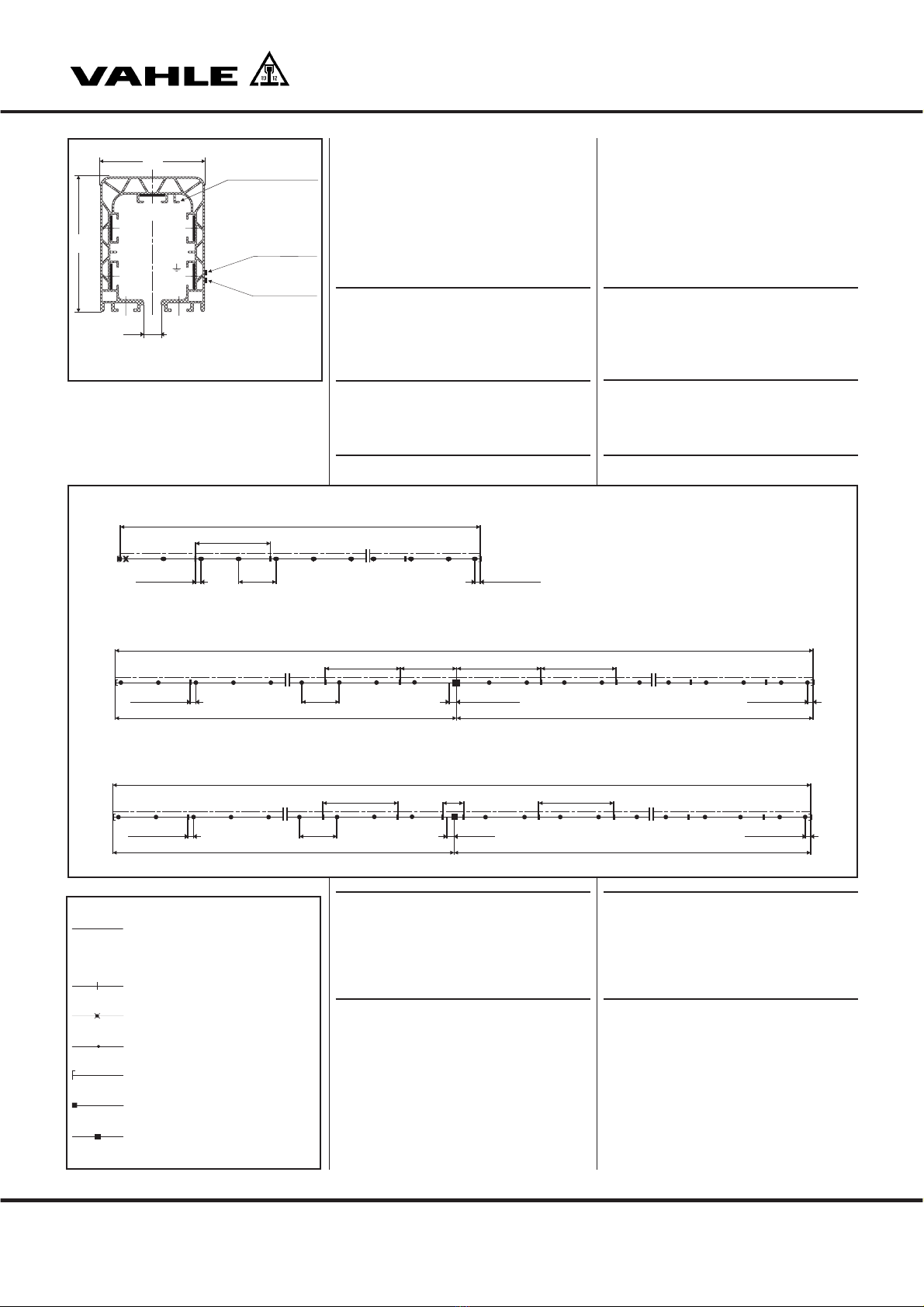
SMontieren Sie bei gerader
Verlegung eine Festaufhän-
gung etwa in der Mitte der
Anlage oder nach Verlegungs-
plan
(
S2).
HDie Schleifleitung muss sich von
dem Festpunkt aus ungehindert
ausdehnen können. Zur Erleich-
terung der Montage kann das
erste Teilstück mit einer Festauf-
hängung festgesetzt werden.
Achtung! Diese Aufhängung
muss nach Beendigung der
Montage wieder zu einer Gleit-
aufhängung umgebaut werden.
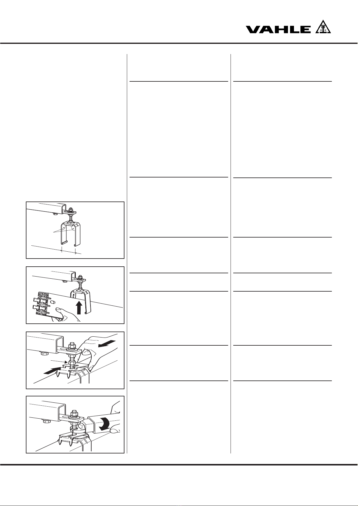
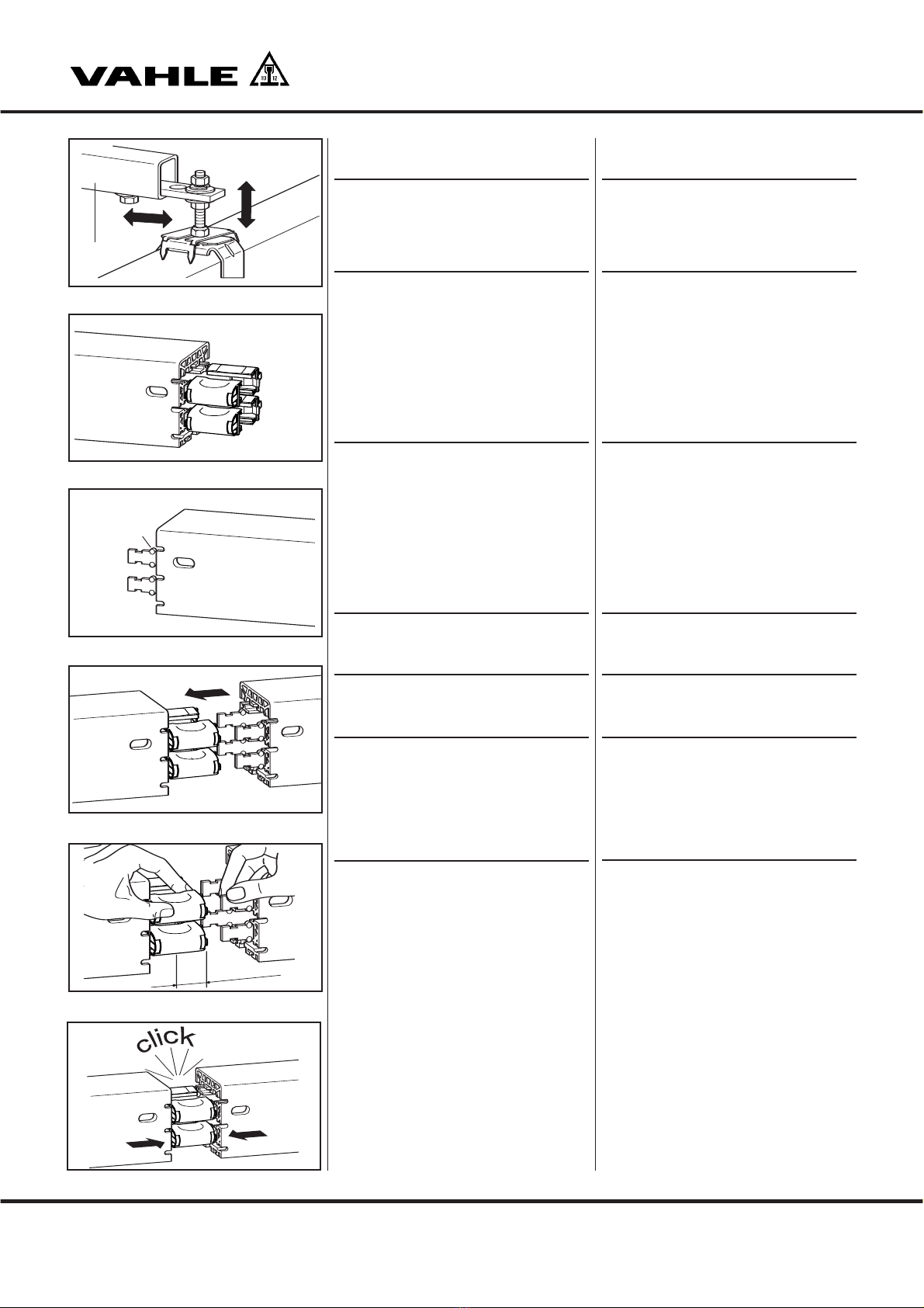
Schleifleitung ausrichten
Richten Sie die Schleifleitung seitlich
aus, indem Sie die Aufhängebolzen in
den Langlöchern der Konsolen
verschieben. (Bei der EHK durch
Verschieben der Halterungen (G5).
Stellen Sie die Höhe mit den Muttern
ein (G5).
HDie Schleifleitung muss genau
fluchtend zur Kranbahn mon-
tiert werden.
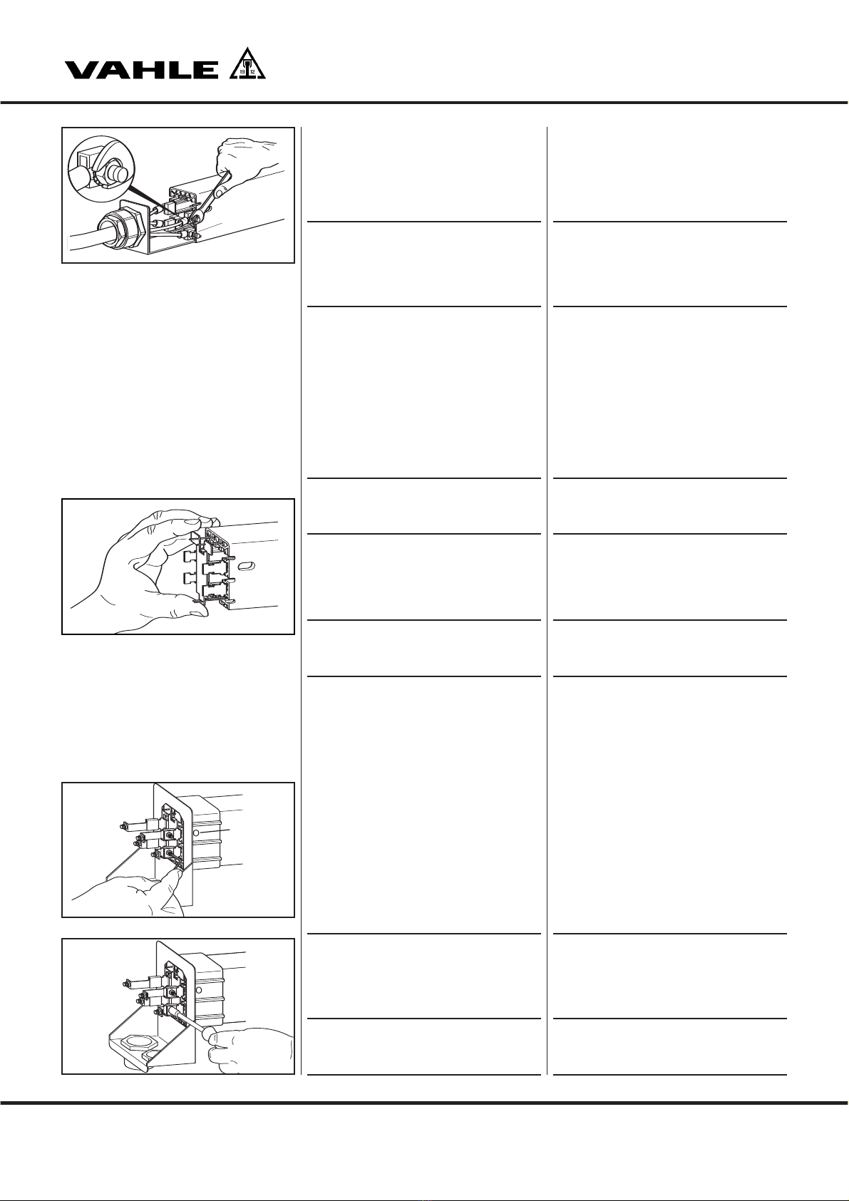
Stromschienenverbindungen
bei KBHF (Federsteckverbinder)
SBei Schleifleitungen KBHF für
40, 63 und 100 A können
Federsteckverbinder verwen-
det werden. Für 125, 160 und
200 A müssen Schraubverbin-
der eingesetzt werden.
(s. KBHS Seite 8).
An den rechten Enden der Kupfer-
schienen sind die Federsteckverbinder
werkseitig vormontiert (G6). An den
linken Enden haben die Kupferschienen
Verformungen (Nocken) (1), die am
Gehäuse anschlagen und die Montage
der Stöße erleichtern (G7).
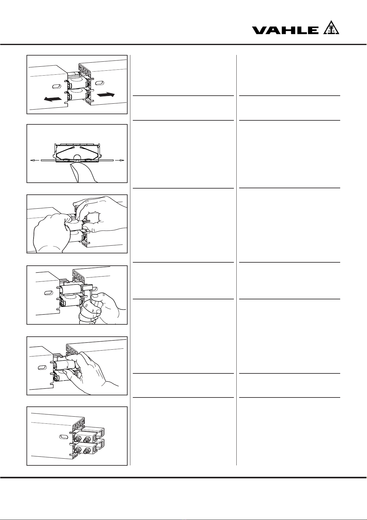
Schieben Sie die gleitend aufgehäng-
ten Teilstücke gegeneinander (G8).
Führen Sie die Kupferschienenenden
in die Federsteckverbinder einzeln
etwa 5-10 mm ein (G9).
Drücken Sie die beiden Gehäuse
soweit zusammen bis eine mechani-
sche feste Verbindung entsteht (G10).
EHK
1
5-10 mm
G5
G6
G7
G8
G9
G10
Tighten the hexagonal nuts with
5 - 7 Nm (G4).
SIf you install a straight run,
install one fixpoint hanger
approximately at the center of
the system or according to the
layout plan
(S2
).
HFree expansion of the powerail
away from the fixpoint must be
possible. Provisionally anchor
the first powerail section with
two fixpoint hangers to facilitate
the further mounting procedure.
Caution! This fixpoint hanger
must be replaced by a sliding
hanger after system installation
has been completed.
Alignment of powerail
Align the powerail laterally by sliding
the support bolts in the slotted holes
of the brackets. (For EHK bracket, by
sliding the supports (G5).
Adjust the height by means of the
nuts (G5).
HThe powerail must be installed
precisely aligned to the
runway.
Powerail joints for KBHF
(plug-in joints)
SFor KBHF powerails for 40, 63
and 100 A, plug-in joints may
be used. For 125, 160 and
200 A, bolted joints must be
used (see KBHS page 8).
At the right ends of the copper connec-
tors, the plug-in joints are factory
preassembled (G6). At the left ends, the
copper conductors feature deformations
(lugs) (1) that attach to the housing and
facilitate the installation of the joints (G7).
Push the sections (suspended from
sliding hangers) against each other
(G8).
Individually and partially insert the
ends of the copper conductors into
the plug-in joints by approx. 5-10 mm
(G9).
Compress the two housings until a
firm mechanical connection is formed
(G10).