Options Available
• Sight glass modification to the metal hydraulic pump reservoir allows the operator to monitor the amount
of material being pumped.
• Air regulator (8607) rated for 3,000 PSI input and gauge (2052L160) rated to 160 PSI. Be sure to refer
to your company’s policies before using anything other than compressor air for your power
source.
• Moisture separator (5604-2) and airline lubricator (5904-2) for protection of the pump.
Part No. Item No. Description Qty.
5001A 1 Cylinder Assembly Complete 1
5001A-1 2 Sealant Cap Assembly Complete 1
5001A-1A 3 Sealant Cap 1
5001-1B 4 Air Return Fitting 1
328034 5 Air Quick Disconnect-Male 1
5001A-1C 6 Lube Pack Extension 1
5001-1D 7 Dowel Pin 6
5001-1E 8 Hydraulic End Cap O-ring 1
5001A-1F 8A Sealant Cap O-rings 1
5001A-2 9 Cylinder Body 1
5001-3 10 Piston Assembly Complete 1
Consists of:
5001-3A .11 Piston Body 1
5001-3B .12 Snap Ring 2
5001-3C .13 Piston Seal Retainer 2
5001-3D .14 Upper & Lower Seal Sets 2
1408-A 15 Cap Screw Bleeder 5/16"-24NF 1
1408-BA 16 Copper Washer 1
5001A-4 17 Hydraulic End Cap 1
BB-12 18 1/2" NPT Body Bleed Fitting 1
5002-1-C Hydraulic Hose Assembly 1
HQD-14-N-M Hyd. Quick Disc. Nipple 1/4" (M) 1
HQD-14-C Hyd. Quick Disc. Coupler 1/4" (F) 1
PA-6-M-2 Hydraulic Pump - Metal Reservoir .. 1
328030 Air Quick Disconnect (F) .1
Part No. Description Qty.
328034 Air Quick Disconnect (M) 1
5016 Sealant Hose Assembly 1
Consists of:
6.Giant Buttonhead Coupler 1
321320 Straight Swivel 1/4" X 1/4" 1
15MGF 15,000 PSI Gauge 1
GC-250 Gauge Guard 1
.25 TEE 1/4" Tee 1
38-120 Hose - 10' X 3/8" 1
331107 .High Pressure Z-Swivel 1
319700 .Shut-off / Bleeder Valve 1
1/4 IN CPLG 1/4"X1/4" Coupling 1
5020-C Compact Cart
Consists of:
5020-1-C Sealant Cap Wrench 1
MINI-QS-5000 Compact Cart 1
5020-3 Pneumatic Tire 2
5020-4 Handle Grips - 1" 3
SC-14 1/4" G.B. Lube Fitting 1
OPTIONS
2052L160 0-160 PSI Gauge 1
5035 O Shaped Sight Glass 1
5040 Hydraulic Fluid - 1 Gallon 1
8607 Air Regulator 1
Delivery: 8 oz. / 30-60 seconds
Weight: 153 Lbs.
Lube Sealant Size: V, P-4
PSI Rating: 10,000
Overall Dimensions: 46" H X 20" W X 26" L
Priming: Self-Priming Air / Hydraulic
CFM Required: 20
Air Pressure Required: 75 - 100 PSI
Pressure Delivered through a 10 foot hose at 100 PSI:
Lube Sealant - 8,000 PSI
Valve Flush - 10,000 PSI
Gauge: Included
Lube Pack Compatible: Yes
Internal Relief Valve: Yes
Val-Tex QS-5000-C
10600 FALLSTONE ROAD • HOUSTON, TEXAS 77099-4390 • ORDER 1-800-627-9771 • PHONE (281) 530-4848 • FAX (281) 530-5225 • WWW.VALTEX.COM
REV. 8/03 18
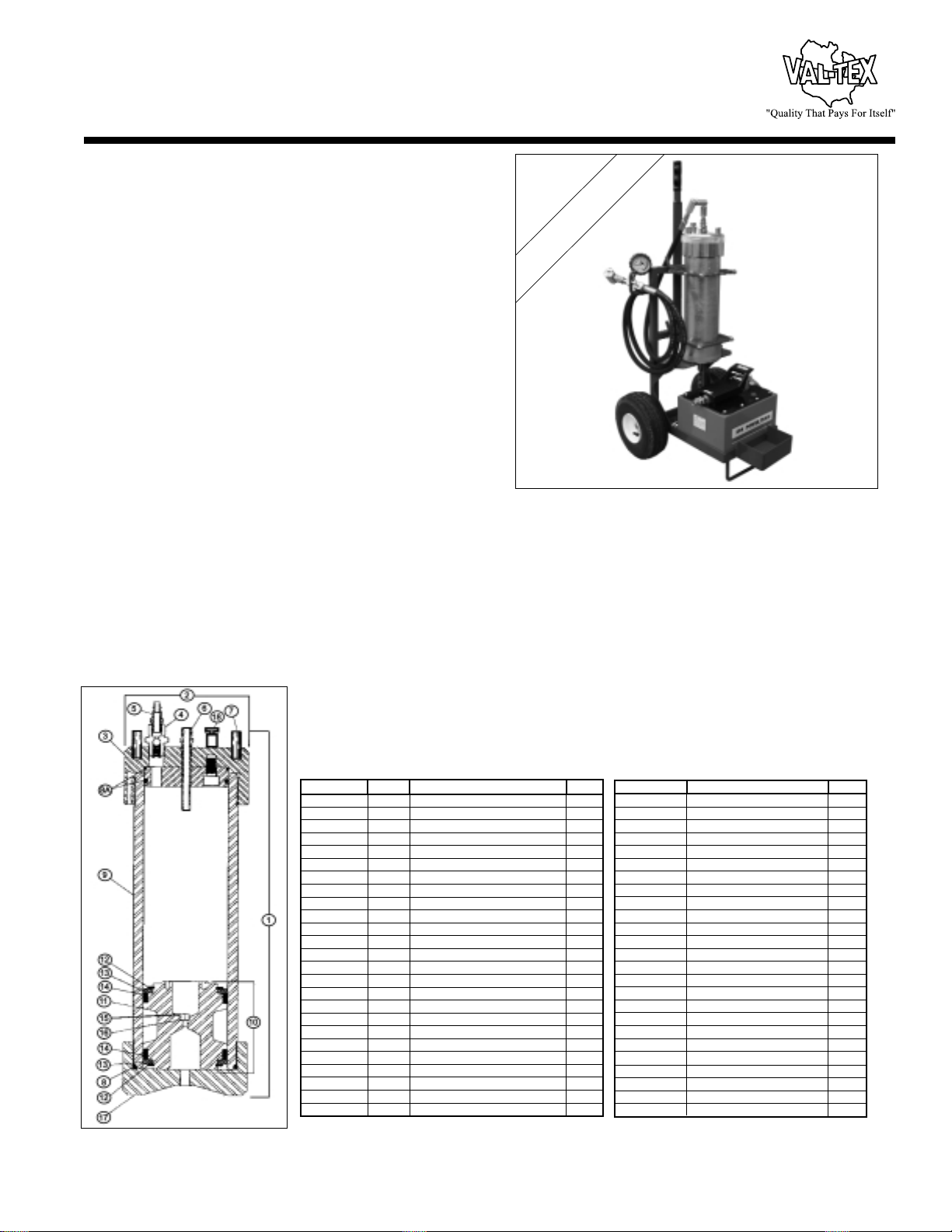
Val-Tex QS-5000-C
The Val-Tex QS-5000-C is a compact, easy to transport, fast, versatile, heavy
duty lubrication unit that will pump large volumes of stick lube sealant, lube
packs, and Valve Flush.The QS-5000-C is quickly separated into two parts by
removing the cylinder for easy loading and unloading by one person.
Assembly is as simple as inserting the two catch pins to secure the cylinder
clamps to the frame.
The QS-5000-C has the largest stick lube sealant capacity in the valve lubrication industry.The Val-Tex five pound V-stick, four pound P-4 Lube
Pack, and one gallon Valve Flush (VF-GAL) are designed to drastically reduce the frequency of loading.
The QS-5000-C’s four inch pneumatic tires allow the unit to be maneuvered easily by one person.The rugged sealant cap wrench has 16 ounce
graduations to allow the operator to control the amount of material being loaded.The unit comes complete with a 10 foot, 3/8 inch I.D. high
pressure hose, quarter turn shut-off / bleeder valve, 15,000 PSI gauge, Gauge Guard, dual swivels, giant buttonhead coupler, and metal hydraulic
fluid reservoir.The hydraulic pump requires only periodic maintenance and has an internal safety relief valve set at approximately 10,000 PSI to
prevent over-pressuring.
Air / Hydraulic Lubrication Gun
EASIER TO TRANSPORT
SAME LARGE CAPACITY