Valor 855 Dimension Instructions for use

© GDC Group Ltd. 2011
5139056/01
Model 855 Dimension Electric Heater.
Fitted with a Blenheim fascia.
(GC No. EF-032-42)
This guide is intended to help you install and care for your Valor electric heater.
Please read carefully before installing and using your heater. However, if further
information is required, our Valor Technical Helpline will be pleased to help.
Telephone 0844 8711 565 (National call rates apply in the United Kingdom).
In the Republic of Ireland Telephone 0044 844 8711 565.
INSTALLER AND OWNER GUIDE
Please keep me in a safe place for future use.
Need to know your Serial
number?
You can find it on the last
page of this guide.

© GDC Group Ltd. 2011.
All rights reserved. No part of this publication may be reproduced in any material form
(including photocopying), stored in any medium by electronic means (including in any
retrieval system or database) or transmitted, in any form or by any means, whether
electronic, mechanical, recording or otherwise, without the prior written permission of
the copyright owner.
Applications for the copyright owner's permission to reproduce any part of this
publication should be made, giving details of the proposed use, to the following
address: The Marketing Communications Manager, GDC Group Ltd, Millbrook House,
Grange Dive, Hedge End, Southampton, SO30 2DF.
Warning: Any person who does any unauthorised act in relation to a copyright work
may be liable to criminal prosecution and civil claims for damages.
Because our policy is one of constant development and improvement, details may vary slightly from
those given in this publication
Safety First.
Valor heaters are CE Approved and designed to meet the appropriate British
Standards and Safety Marks.
Quality and Excellence.
All Valor heaters are manufactured to the highest standards of quality and excellence
and are manufactured under a BS EN ISO 9001 quality system accepted by the
British Standards Institute.
Page 2
© GDC Group Ltd. 2011
INSTALLER AND OWNER GUIDE

CUSTOMER CARE
Thank you for choosing Valor.
All Valor heaters are designed to meet the most stringent quality, performance
and safety requirements to provide our customers with many years of trouble free
service. This guide aims to improve your understanding and appreciation of your new
Valor heater, by providing simple and informative instructions to enable you to install it
and to ensure that you benefit from the excellent performance and features it has to
offer.
If you require further assistance, the Valor Technical Helpline will be pleased to
help.
Please telephone 0844 8711 565 (local rates apply in the United Kingdom). In the
Republic of Ireland please telephone 0044 844 8711 565.
1. IMAGE
INSTALLER AND OWNER GUIDE
Page 3
© GDC Group Ltd. 2011

2. HANDLING AND UNPACKING
Before continuing any further with the installation of this heater please read the
following:
Important instructions.
The approximate lifting weights (kg) of the heater parts are listed below:
Model Heat engine Fascia Firefront & ash pan Optional Spacer
Blenheim 7.6 2.0 3.5 1.0*
*See section 4.
One person should be sufficient to lift the heater. If for any reason this weight is
considered too heavy then obtain assistance.
When lifting always keep your back straight. Bend your legs and not your back.
Avoid twisting at the waist. It is better to reposition your feet.
Avoid upper body / top heavy bending. Always bend from the knees rather than the
waist. Do not lean forward or sideways whilst handling the heater.
Always grip with the palm of the hand. Do not use the tips of fingers for support.
Always keep the heater as close to the body as possible. This will minimise the
cantilever action.
Use gloves to provide additional grip.
Always use assistance if required.
3. SAFETY
This appliance is not intended for use by persons (including children) with reduced
physical, sensory or mental capabilities, or lack of experience and knowledge, unless
they have been given supervision or instruction concerning use of the appliance by a
person responsible for their safety.
Children should be supervised to ensure that they do not play with the appliance
Always
Always install the heater in accordance with this guide. If in doubt obtain
expert advice.
Always make sure the electrical socket is accessible and located adjacent to, but
not above or behind the heater.
Always disconnect the heater from the electrical supply before carrying out
cleaning or maintenance.
Always use a fireguard when young children and infirm persons can come into
contact with the heater.
Always use genuine Valor spares.
INSTALLER AND OWNER GUIDE
Page 4
© GDC Group Ltd. 2011

Never
Never leave children unsupervised in a room where the heater is ON and
unguarded.
Never use the heater in a small room when occupied by persons not able to leave
the room by themselves unless constantly supervised.
Never obstruct or cover the fan outlet or force items into heater openings.
Never install or use the heater anywhere where water or high humidity is in use,
i.e. Bathrooms, Kitchens, Shower Rooms and Swimming Pools etc.
Never use aerosols or steam cleaners on or around the heater.
Never route the electric cable under carpet etc.
Never install the heater close to curtains or combustible materials.
Never use the heater to dry clothes etc.
Never sit or stand on the heater.
Never use the heater with a timer switch or similar device.
Important Electrical Safety
The heater must not be located in front of or under an electrical socket; the socket
must always be accessible in order to disconnect the heater from the electrical supply
for maintenance and cleaning.
CAUTION: In order to avoid a hazard due to inadvertent resetting of the thermal cut out,
this appliance must not be supplied through an external switching device, such as a
timer, or connected to a circuit that is regularly switched on and off by the utility.
Important! This heater must be earthed.
The heater is supplied with a 3 pin 13 Amp fused moulded plug with 1mm² 3 core
cable.
The wires in the cable are coloured in accordance with the following code:-
Live = Brown
Neutral = Blue
Earth = Green /Yellow
The electric supply must be safely routed from the heater to an electrical socket.
If the electric cable is damaged, to avoid a hazard it must be replaced by a Valor
authorised service agent, or similarly qualified person.All external wiring between
the heater and the electrical supply shall comply with current IEE regulations.
Extension leads should not be used.
INSTALLER AND OWNER GUIDE
Page 5
© GDC Group Ltd. 2011

4. OPTIONAL SPACER FRAME KIT
An optional spacer frame kit is obtainable either from your heater supplier or direct
from Valor Sales. The kit is an 75mm deep spacer kit (Kit number 05801T1). This
spacer enables the heater to be flat wall fixed.
Spacer frame kit 05801T1.
5. FASCIA CONTENTS
INSTALLER AND OWNER GUIDE
Page 6
© GDC Group Ltd. 2011
Figure 2.
Contents Quantity (Illustrations are not to scale)
75mm deep spacer
frame 1
No 8 x 3/8 Self- tapping
screws 4
Figure 1.

6. HEATER CONTENTS
INSTALLER AND OWNER GUIDE
Page 7
© GDC Group Ltd. 2011
Contents Quantity (Illustrations are not to scale)
Heater 1
No. 8 x 3/8 pan head
screw 5
Tension wire 1
Mains cable 1
Securing clamp 1
M5 x 40mm Securing
clamp screw 1
Screw eye 1
Wood screw 5
Wall plug 5
Figure 3.

7. HEATER DIMENSIONS
8. WHERE AND HOW CAN I FIT THE HEATER?
Important: Before continuing with the installation of this heater please ensure
that you have completed the information on the last page of this guide.
Please read this section thoroughly before positioning the heater.
Do I need any tools?
Depending upon the chosen method of installation you may need the following tools: -
For Optional Spacer frame or screw fixed installations you will need a cross head
screwdriver. This should have a number 2 size tip.
If wire fixing and drilling into brickwork you will need a power drill (preferably with
hammer action) and appropriate size drill bit for the wall plugs supplied.
Where and how can I fit the heater?
Q Can the heater be installed into a ‘hole in the wall’ (elevated opening)?
A We do not recommend the heater be used for this type of installation.
Q Do you want to fit the heater into a surround or fireplace opening without
the optional spacer frame?
A The minimum rebate / depth required is 70mm.
INSTALLER AND OWNER GUIDE
Page 8
© GDC Group Ltd. 2011
Figure 4. Dimensions (All dimensions are subject to manufacturing tolerances)

Q Do you want to fit the heater against a flat wall with the base of the heater
on a hearth or similar surface?
A You will need to purchase an optional spacer frame kit - See section 4. This
spacer enables the heater to be flat wall fixed. The depth of the spacer frame is
75mm.
Q What opening size do you need in the surround or fireplace opening?
A This heater can be fitted into fireplaces or surrounds where the following
dimensions are available.
Width 395mm - 450 mm
Height 555mm - 590 mm
Depth At least 70mm
Q Do you want to fit the heater below a shelf, mantle or similar?
A You will have to allow the clearances as shown below:
The minimum height from the base of the heater to the underside of any shelf made
from wood or other combustible materials is detailed below.
• For a shelf up to 150mm deep: Minimum height = 700mm.
• For a shelf deeper than 150mm: 700mm + 12.5mm for every 25mm depth over
150mm (See Figure 5).
INSTALLER AND OWNER GUIDE
Page 9
© GDC Group Ltd. 2011
Figure 5. Combustible shelf clearances

Q Do you want to fit the heater directly onto carpet?
A Although the heater can be fitted directly onto carpet we do not recommend this.
The reasons for this are:
It may be difficult to stand the firefront and ash pan on certain carpets.
The filter may require more frequent cleaning.
It is important that rugs and other objects do not obstruct the air openings at the
bottom of the heater.
General notes to read before fitting your heater.
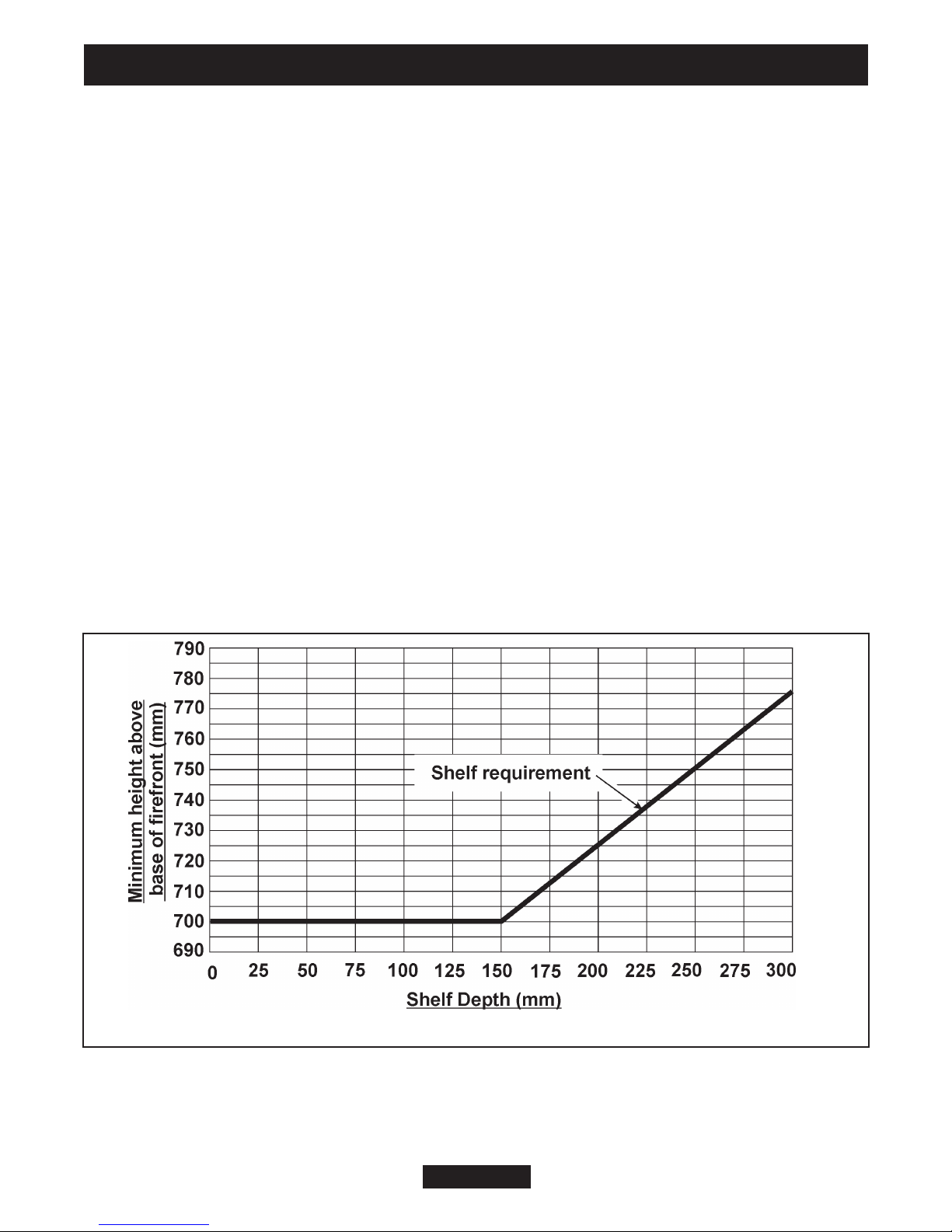
If fitting the heater onto a reflective or shiny surface such as a hearth we
recommend that this surface does not extend further than 300mm from the fixing
plane (wall). Reflective or shiny surfaces that project further than 300mm may
reflect an image of the internal light source.
When the fuel effect is on, it will be possible to see reflected light and movement
behind the outlet louvre at the top of the heater.
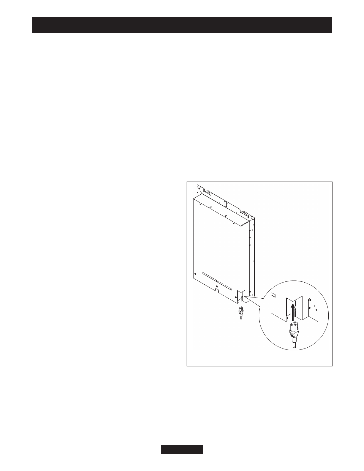
Fitting the mains cable.
The heater is supplied with a mains cable
assembly that should be connected to the
heater prior to installation. The heater
connector is located at the rear bottom left
(See figure 6).
The mains cable guides.
At the base of the heater you will find two
electric cable guides, one each side of the
heater. If required, the cable guide on the
right hand side (looking from the front of the
heater) can be removed and put in the
rectangular slot in the centre rear of the
heater. For removal and fitting please see
the following sections.
Removing the cable guide.
1. Before removing the cable guide please
note that the wider part of the cable guide is on the outer edge of the base (See
figure 7 - Item 1).
2. To remove the cable guide push and lift the tab on the bottom. The bottom of the
cable guide will open (See figure 7 - Item 2).
3. Hold the bottom of the cable guide close to the heater then gently pull the cable
guide away from the rectangular slot (See figure 7 - Item 3).
INSTALLER AND OWNER GUIDE
Page 10
© GDC Group Ltd. 2011
Figure 6. Fitting the mains cable

Fitting the cable guide.
When fitting the cable guide please remember that the wider part of the cable guide
has to be fitted against the outer edge of the base (See figure 7 - Item 1).
1. Gently pinch the sides of the cable guide (See figure 7 - Item 4) and push the
cable guide into the required rectangular slot.
2. Place the electrical cable into the guides and close the top of the cable guides.
Securing the Heater.
The heater must be secured into position to prevent it from being tipped over.
The following securing options are available:
Method A - Securing the heater with Screws.
Method B - Securing the heater with Wire.
Method C - Securing the heater using the Optional Spacer Frame (kit number
05801T1).
Method D - Securing the heater using the Securing clamp.
If fitting the heater into a fireplace or surround opening, try the heater in the opening
to ensure that it will fit.
Never hold the hood / canopy on the front of the heater when lifting.
If fitting the heater onto a decorative hearth surface such as marble or tile it is
advisable to protect the hearth surface. Do not drag the heater as the surface finish
may be damaged.
INSTALLER AND OWNER GUIDE
Page 11
© GDC Group Ltd. 2011
Figure 7. Removing and positioning the cable guide.
Item 1 Item 2
Item 3 Item 4

Method A - Securing with screws.
Note - If fixing to marble it is recommended that
Method B - ‘Securing with wire’ is used. Drilling
marble without the correct tools and experience
may result in the marble cracking.
1. Place the heater into the fireplace or surround
opening. Make sure that the heater is in the
middle of the surround or fireplace.
2. There are two slotted holes in the top of the
heater and four holes in the side flanges (See
figure 8). We recommend the use of two upper
holes and two lower holes. Mark through the
required holes so that their position is clear when
the heater is removed.
3. Remove the heater.
4. Drill an appropriate size hole in each of the
marked positions for the wall plugs supplied.
Insert wall plugs into the drilled holes.
5. Place the heater so that the holes are in line
with the wall plugs in the fixing surface.
6. Screw and secure the heater with four wood
screws (See figure 3).
Method B - Securing with wire.
This method of securing is recommended where the wall / brickwork is in poor
condition or where marble back panels / surrounds are used.
Although this section deals with fireplace openings without a spacer, this method of
securing the heater it can also be used with the optional spacer frame (See method
C).
1. The fixing kit supplied with the heater
includes a wire and screw eye. These can be
used to secure the heater to the back of a
surround / fireplace opening.
2. Mark the screw eye position on the centre
line at the back of the fireplace opening and at
a height of 565-575mm (See figure 9).
3. Drill an appropriate size hole in the marked
position.
4. Insert a wall plug into the drilled hole.
5. Screw the screw eye into the wall plug.
Page 12
© GDC Group Ltd. 2011
INSTALLER AND OWNER GUIDE
Figure 8. Screw location
Figure 9. Screw eye location

6. Position the heater in front of the fireplace
opening.
7. At the top of the heater there are four
small holes, two each side of the heater.
From the front of the heater, thread about
50mm of the wire into the outside small hole
on the right side of the heater (See point 1 -
figure 10).
8. Thread the other end of the wire through
the remaining small hole to the left. Continue
to push the wire through this hole until there
is only a small loop of wire at the front of the
heater (See point 2 - figure 10).
9. At the back of the heater there will be a
long piece and a short piece of wire coming
through the two holes. Hold the short piece
and give the long piece a gentle tug. This will
secure the wire. Take the long piece and thread this through the screw eye in the
back of the fireplace opening (See figure 10).
10. From the back of the heater thread the long piece of wire through the inner small
hole on the left hand side of the heater (See figure 10).
11. Locate the heater in the fireplace opening, then from the front of the heater, gently
pull the wire on the right hand side to gather up the excess until the heater is secure.
Thread the wire through the remaining small hole to lock the wire and heater in place
(See point 4 - figure 10).
Method C - Securing with the Optional Spacer Frame.
The spacer frame enables the heater to be flat wall fixed. For your safety the frame
and heater must be securely fixed to the rear wall / surround.
Fitting the spacer frame
The rear of the spacer has two screw
location slots in the top flange. These
should be to the rear when fitting.
1. Position the spacer frame against the
wall. Ensure that the spacer frame is
central to the fireplace.
2. The top rear flange of the spacer frame
has two screw locations. Mark the
positions of the two screw locations on the
rear wall (See figure 11).
3. Remove the spacer frame from the
fireplace and place away from the work area.
4. Drill the locations using a suitably sized masonry drill bit for the wall plugs supplied.
Page 13
© GDC Group Ltd. 2011
INSTALLER AND OWNER GUIDE
Figure 10. Wire fix
Figure 11. Location points

5. Insert two wall plugs provided into the holes.
6. Insert a woodscrew into each hole and screw in until there is approximately 6mm of
screw protruding from the wall.
Preparing the heater for installation.
1. Secure the spacer frames to the heater using four
No.8 x 3/8 screws supplied (See figure 12).
Fitting the heater.
1. Carefully lift the heater and locate the slots on the
rear of the spacer frame onto the screws in the wall.
The screws can be adjusted to ensure a tight fit. When
mounting to decorative surfaces such as wallpaper be
careful not to drag the heater down the wall as this may
damage the decorative surface.
Method D - Securing with the clamp.
This method of securing cannot be used in conjunction
with the optional spacer frame. This is an alternative
securing method where fixing to a surround or rear wall
proves impractical.
1. Locate the clamp as in point 1 of figure 13. Place the screw through the upper
bracket on the heater and locate into the clamp - point 2 of figure 13. It is only
necessary to locate the screw, do not continue to turn it as this will elevate the clamp.
2. Place the heater into the surround / opening.
3. Rotate the clamp
screw clockwise
until the heater is
secured in the
surround / opening.
Where applicable,
do not over-tighten
the screw as this
may deform or
cause damage to
the surround /
back panel.
INSTALLER AND OWNER GUIDE
Page 14
© GDC Group Ltd. 2011
Figure 13.
Figure 12. Fitting the
spacer frame to the heater.

9. LIGHT SHUTTER ADJUSTMENT
The light shutter is an adjustable plate that increases and
decreases the appearance of the flames in the flame effect.
1. Switch on the fuel effect. If you are satisfied with the
appearance of the flame effect there is no need to adjust the
light shutter.
2. To gain access to the light shutter, unscrew and remove the
thumbscrew from the bottom of the filter panel. Gently pull the
base of the filter panel forward and down to remove it from the
heater (See figure 14). There is a black card baffle in front of
the light shutter; hold both sides and gently pull this forward to
gain access to the light shutter (See figure 15).
3. To adjust the light shutter, loosen the two screws then lift the
shutter to increase the appearance of the flames or lower it to
decrease the appearance of the flames (See
figure 16).
4. When you have obtained the required flame
appearance, tighten the two screws and secure
the shutter in place, replace the card baffle and
filter panel.
INSTALLER AND OWNER GUIDE
Page 15
© GDC Group Ltd. 2011
Figure 16.
Figure 15.
Figure 14.

10. FITTING THE FASCIA
Fitting the Blenheim fascia frame.
1. Remove the fascia frame from its
packaging.
2. There are four magnets supplied.
Locate the magnets to the heater body
(See figure 17). Ensure that they are
located correctly before fitting the fascia
frame.
3. Locate the fascia frame onto the
heater.
Fitting the Blenheim fascia trims.
1. Remove the fascia trims from the
packaging.
2. There are six magnets supplied.
Locate the magnets to the heater frame
(See figure 18). Ensure that they are located
correctly before fitting the fascia trims.
3. Locate the fascia trims onto the frame. Ensure that
the side trims are located before the top trim.
Fitting the firefront and ash pan.
1. Remove the firefront from its packaging.
2. Locate the firefront casting.
3. Position the ash pan beneath the firefront.
INSTALLER AND OWNER GUIDE
Page 16
© GDC Group Ltd. 2011
Figure 18.
Figure 17.

INSTALLER AND OWNER GUIDE
Page 17
© GDC Group Ltd. 2011
11. OPERATING THE HEATER
Never cover the firefront or obstruct the opening at the base of the firefront,
this could cause overheating and consequent risk of fire.
The heater is controlled by three switches located on the
upper right hand side (See figure 19).
The heat settings are quoted using a 240V ~ 50Hz supply.
What do the switches do?
The upper switch (The effect switch).
Pressing the bottom of the switch marked turns
the effect on. An internal fan is used to produce the
flickering flame effect, room temperature air will be felt
coming from the outlet at the top of the firefront.
Pressing the top of the switch marked turns the
effect off. No air will be felt coming from the outlet at the
top of the firefront.
The middle switch (The 675 watt heat switch).
For the middle switch to work the upper switch has to be in the position.
Pressing the bottom of the switch marked will turn the 675 watt heater on.
Warm air will be felt coming from the outlet at the top of the firefront.
Pressing the top of the switch will turn the 675 watt heater off.
The bottom switch (The 1350 watt heat switch).
For the bottom switch to work the upper switch has to be in the position and
the middle switch has to be in the position.
Pressing the bottom of the switch marked will turn the 1350 watt heater on.
Warm air will be felt coming from the outlet at the top of the firefront.
Pressing the top of the switch will turn the 1350 watt heater off.
Please note that the 675 watt or 1350 watt switches can be left in the desired
positions and the upper switch used as a master on/off switch.
Figure 19.

12. CLEANING THE HEATER
Important Safety.
Before undertaking maintenance always disconnect the heater from the electricity
supply by removing the 3 pin plug and allowing the heater to cool.
How do I Clean my heater?
The heater and plastic parts need only to be wiped clean with a dry soft cloth; do not
use polishes or abrasive materials. This is especially important when cleaning the
effects screen.
Cleaning the filter panel.
The filter panel requires regular cleaning. We recommend cleaning the filter at least
once a month. The filter may require cleaning more frequently depending upon use.
To gain access to the filter remove the ash pan and lower firefront casting. It is not
necessary to remove the filter for cleaning. Clean the filter using a vacuum fitted with
a soft brush attachment. Do not apply pressure to the filter as this may cause
damage.
13. HELP AND ADVICE
I have a problem with my heater!
1. My heater is switched on but there is no effect or heat.
The first thing to do is check the wall socket. To do this plug in a known working
appliance. If the appliance you have plugged in works then there is a good chance
that the problem lies with the 13 Amp fuse in the heater plug. If either fuse or socket
is suspected, have them checked by an electrician.
2. My heater is on, I have selected a heat setting but
there is no heat, just the effect.
A cut out device is fitted to the heater to prevent damage
due to over heating. If it operates due to an obstruction in
the airflow, the heater must be turned off and allowed to
cool for 15 minutes and the obstruction removed before
restarting. Check that the filter panel is clean (See ‘cleaning
the filter panel’ above).
3. I have dark areas in the fuel effect of my heater or the
fuel effect is not as bright as it was when new.
There is a mirror fitted to the rear of the hood / canopy at
the front of the heater and this may need cleaning. Wipe the
mirror with a clean, dry non abrasive cloth (See figure 20).
INSTALLER AND OWNER GUIDE
Page 18
© GDC Group Ltd. 2011
Figure 20.

4. I have a problem that is different to those in the previous examples 1- 3.
For general advice about your heater, to report faults, arrange for your heater to be
serviced, or for sales and product information call 0844 8711 565. Callers in the
Republic of Ireland please telephone 0044 844 8711 565.
For spares inquiries
Spare parts are available nationwide via the ‘interpart stockist network’. For
your local stockist consult Yellow pages under ‘Central Heating’.
When ordering spare parts for your heater please have the below information
available. This will help us to deal with your call quicker and avoid you having to
make a second call.
Your Post Code
The fault, problem or request.
Model, Name and serial number (This information should have been recorded on
the last page of this guide and can also be found on a small label attached to the
filter panel of the heater (See figure 22)
14. ENVIRONMENT
Environmental Protection.
Waste electrical products should not be disposed of with household waste.
Please recycle where facilities exist. Check with your local authority or
retailer for recycling advice.
What should I do when I’m ready to dispose of my heater?
The plug should be removed from the mains cable and the mains cable removed from
the heater. These should be disposed of with the heater.
INSTALLER AND OWNER GUIDE
Page 19
© GDC Group Ltd. 2011

15. WIRING CIRCUIT SCHEMATIC
16. WARRANTY AND SERVICE
Information for the customer.
Standard Warranty Terms & Conditions
The warranty is for 12 months subject to contract.
In the United Kingdom servicing can be carried out either by a heateam service
engineer or a suitably qualified person.
You must register your heater with heateam, the service division of Baxi Heating UK
Limited, either by completing and returning the registration card or calling our free
telephone registration line on 0800 032 72 44.
Our promise to you
If you experience a fault with your new heater, we aim to provide a safe and high
quality repair service supported by our dedicated national network of highly skilled
engineers. Nothing in this warranty will affect your statutory rights.
INSTALLER AND OWNER GUIDE
Page 20
© GDC Group Ltd. 2011
Figure 21.
Table of contents
Other Valor Electric Heater manuals

Valor
Valor 850 Instructions for use

Valor
Valor alisa 802 Instructions for use

Valor
Valor 805 alsace Installation guide

Valor
Valor 814 GEORGIAN Instructions for use

Valor
Valor 802 Installation guide

Valor
Valor 805 alsace Instructions for use

Valor
Valor accolade 806 User manual

Valor
Valor 807 Instructions for use
Popular Electric Heater manuals by other brands

Bromic Heating
Bromic Heating Tungsten 2000W Installation, instruction and service manual

Valor Fires
Valor Fires 833 Installer and owner guide

Heatmaster
Heatmaster U2BS-R24 instruction manual

Kroll
Kroll E8 operating instructions

Comfort Glow
Comfort Glow QDE8600 owner's manual

Intertec Data Systems
Intertec Data Systems E Series operating instructions