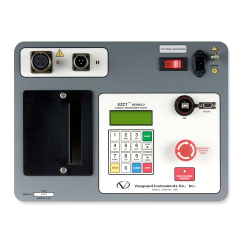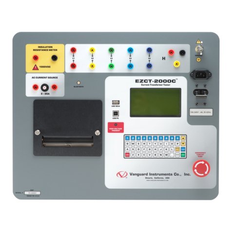
Operating Procedures EZCT and EZCT-10
3
1.0 INTRODUCTION
1.1 Applicability
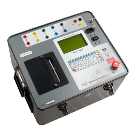
This manual applies to the Model EZCT™ and Model EZCT-10™ (hereafter, EZCT), made by
Vanguard Instruments Company, Inc.
1.2.General Description
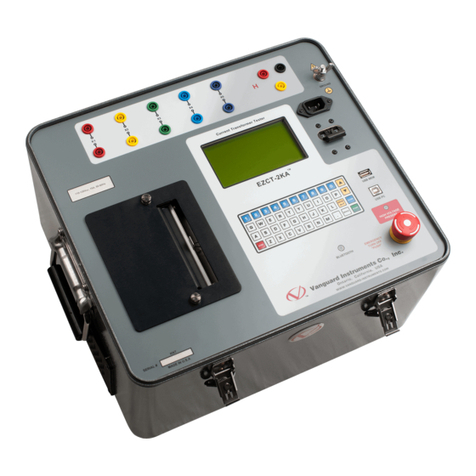
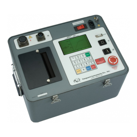
The EZCT is a microprocessor based current transformer (CT) test set. This rugged yet portable
test set measures CT excitation voltage and current, turns ratio, and winding polarity on single or
multi-ratio current transformers.
The EZCT provides a variable AC test voltage up to 1,200Vac for the CT excitation test. Test
voltage and excitation current readings are displayed on the LCD and recorded during a test.
Once the test is completed, users can print the CT excitation curves and test data and/or save the
test results in FLASH EEPROM.
The CT turns ratio is determined by dividing the measured excitation voltage applied to the CT
secondary winding by the induced voltage measured on the CT primary winding.
The EZCT has a 16-key pushbutton pad for entering test parameters and control functions. Test
voltage is raised or lowered by a Voltage Control knob. A 4-line by 20-character LCD readout is
used for displaying control-option menus and test data. The EZCT has a built-in thermal printer,
for printing test data on 4.5-inch-wide thermal sensitive paper.
The EZCT can be used in the stand-alone-mode or in the computer-control mode. In stand-alone
mode, all tests are conducted from the EZCT front panel. Operation only requires connecting the
test leads to the current transformer primary and secondary windings and following the test
sequence displayed on the LCD. Knee point voltages (IEEE 45, IEEE 30, ANSI 10/50) are
calculated automatically by the EZCT. Current transformer excitation curves, knee point
voltages, and turns ratio can be printed on the thermal printer.
Up to 10 tests can be stored in one record. A test contains excitation curve data (typically, 32 data
points per curve), knee point voltages, and turns ratio reading. Up to 128 records can be stored in
FLASH EEPROM memory. Operators can recall the stored test records at a later time for review
and printing.
The Computer Interface mode allows the user to run excitation and ratio tests from the PC or to
retrieve test records stored in the EZCT to the PC’s memory.
A RS232 serial cable, and a Windows-Based PC Current Transformer Analysis Software (on
CD) is supplied with each EZCT.
This manual will focus on the stand-alone mode for the EZCT.
1.3 Functional Description
The EZCT performs the current transformer excitation test following the ANSI/IEEE C57.13.1-
1981 (IEEE Guide for Testing of Relaying Field Current Transformers). To find the current
transformer excitation curve, the EZCT applies an AC test voltage to the secondary winding of
the current transformer. The test voltage is first raised until the current transformer achieves
saturation. The test voltage is then slowly lowered to zero volts. Test voltage and current
readings are recorded until the test voltage reaches zero volts.
Knee point voltages (IEEE-30, IEEE-45, ANSI-10/50) are calculated automatically by the EZCT.
