Vanguard Instruments CVT-765 User manual

CVT-765
Capacitor Voltage Transformer Ratio Tester
USER’S MANUAL
Vanguard Instruments Company, Inc.
1520 S. Hellman Ave.
Ontario, California 91761, USA
TEL: (909) 923-9390
FAX: (909) 923-9391
May 2011
Revision 1

CVT-765 USER’S MANUAL REV 1
i
SAFETY SUMMARY
FOLLOW EXACT OPERATING PROCEDURES
Any deviation from procedures described in this User’s Manual may create one or more safety
hazards, damage the CVT-765, damage the test transformer, or cause errors in the test results.
Vanguard Instruments Company, Inc. assumes no liability for unsafe or improper use of the
CVT-765.
SAFETY WARNINGS AND CAUTIONS
The CVT-765 shall be used only by trained operators. All transformers under test shall be off-
line and fully isolated. Always ground the CVT-765 to a substation ground before connecting
the test cables to a transformer. Do not perform test procedures or service unless another
person is also present who is capable of rendering aid and resuscitation.
DO NOT MODIFY TEST EQUIPMENT
To avoid the risk of introducing additional or unknown hazards, do not install substitute parts or
perform any unauthorized modification to any CVT-765 test unit. To ensure that all designed
safety features are maintained, it is highly recommended that repairs be performed only by
Vanguard Instruments Company factory personnel or by an authorized repair service provider.
Unauthorized modifications can cause safety hazards and will void the manufacturer’s
warranty.
WARNING
Do not remove test leads during a test. Failure to heed this warning can result in electrical
shock to personnel and damage to the equipment.

REV 1 CVT-765 USER’S MANUAL
ii
TABLE OF CONTENTS
CONVENTIONS USED IN THIS DOCUMENT ..................................................................................... 1
1.0 INTRODUCTION.................................................................................................................... 2
1.1 General Description and Features ................................................................................... 2
1.2 Technical Specifications ................................................................................................... 3
1.3 Controls and Indicators.................................................................................................... 4
2.0 PRE-TEST SETUP ................................................................................................................... 6
2.1 Operating Voltages .......................................................................................................... 6
2.2 LCD Screen Contrast Control............................................................................................ 6
3.0 OPERATING PROCEDURES ................................................................................................... 7
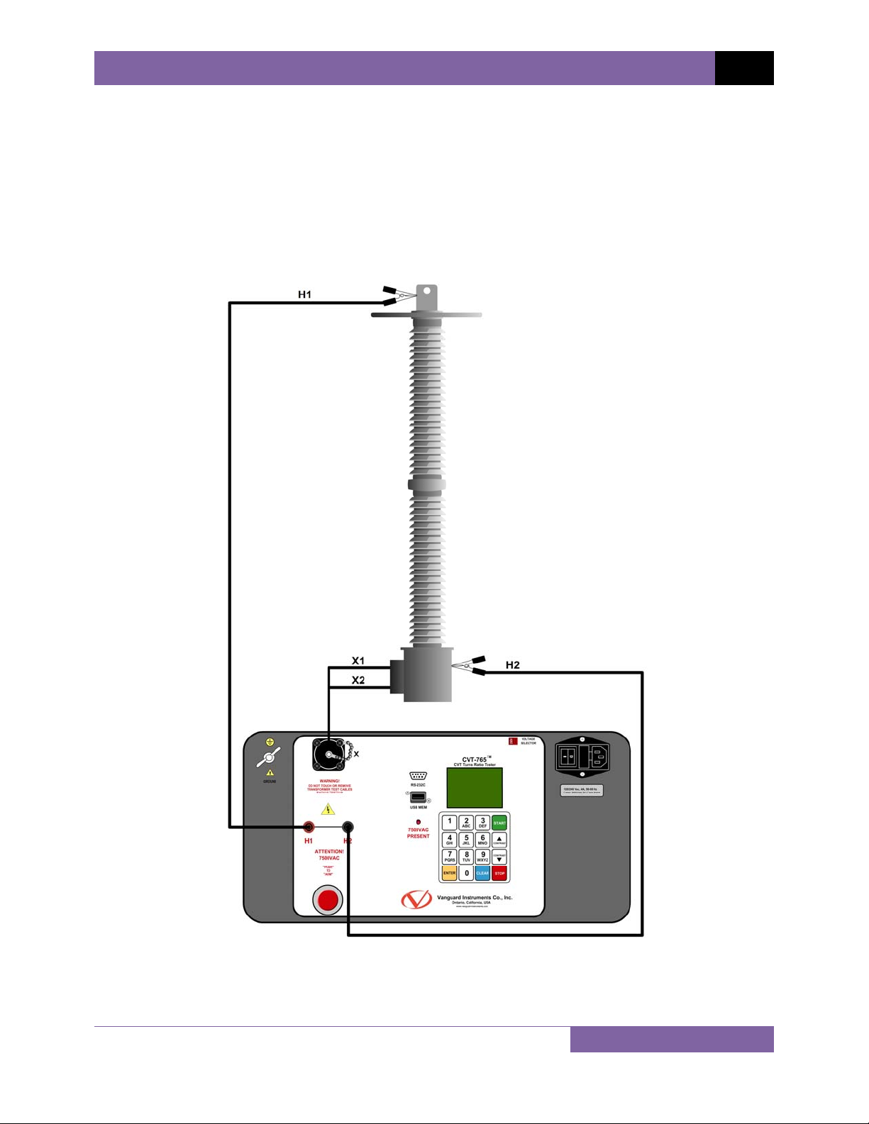
3.1 Connection Diagram ........................................................................................................ 7
3.2 Setting the Date and Time ............................................................................................... 8
3.3 Setting the Interface Language........................................................................................ 9
3.4 Setting the Frequency (50 or 60 Hz) .............................................................................. 10
3.5 Performing Tests............................................................................................................ 11
3.5.1. Entering Test Record Header Information ............................................................. 11
3.5.2. Performing a Transformer Test .............................................................................. 15
3.6 Working With Test Records ........................................................................................... 20
3.6.1. Viewing the Contents of the Working Memory ..................................................... 20
3.6.2. Saving Test Results to a Test Record ...................................................................... 21
3.6.3. Restoring a Test Record From Flash EEPROM........................................................ 24
3.6.4. Restoring a Test Record From a USB Flash Drive ................................................... 28
3.6.5. Copying Test Records to a USB Flash Drive............................................................ 31
3.6.6. Viewing the Test Record Directory......................................................................... 34
3.6.7. Erasing Test Records from the Flash EEPROM ....................................................... 36
3.6.8. Erasing Test Records from a USB Flash Drive......................................................... 40
LIST OF TABLES
Table 1. CVT-765 Technical Specifications...................................................................................... 3
Table 2. Functional Descriptions of CVT-765 Controls and Indicators ........................................... 5
LIST OF FIGURES
Figure 1. CVT-765 Controls and Indicators ..................................................................................... 4
Figure 2. Typical CVT-765 Cable Connections................................................................................. 7

CVT-765 USER’S MANUAL REV 1
1
CONVENTIONS USED IN THIS DOCUMENT
This document uses the following conventions:
•A key, switch, or knob on the CVT-765 is indicated as [KEY], [SWITCH], [KNOB].
•Menu names are referenced as “MENU NAME”
•CVT-765 LCD screen output is shown as:
•When instructions are provided, the menu item that should be selected is outlined with a
rectangle as shown below (option 3 should be selected):
•Warning messages are indicated as:
WARNING
Warning message
•Important notes are indicated as:
NOTE
Note details
1. OPTION 1
2. OPTION 2
3. OPTION 3
4. OPTION 4
5. OPTION 5
1. OPTION 1
2. OPTION 2
3. OPTION 3
4. OPTION 4
5. OPTION 5

REV 1 CVT-765 USER’S MANUAL
2
1.0 INTRODUCTION
1.1 General Description and Features
The Vanguard CVT-765 is a microprocessor-based, single phase, automatic, transformer turns-
ratio tester. This portable test unit is specifically designed to measure the turns-ratios of
Capacitor Voltage Transformers (CVT’s).
The CVT-765 determines the transformer turns-ratio using the IEEE C57.12.90 measuring
method. It uses a 7500Vac excitation voltage source to accurately measure the turns-ratio of
Capacitor Voltage Transformers with a rating of up to 765KV. The transformer turns-ratio is
determined by precisely measuring the voltages across the unloaded transformer windings.
The CVT-765 can measure the turns-ratios of Capacitor Voltage Transformers ranging from 75
to 15,000. The measured turns-ratio, winding polarity, and winding phase angle are displayed
on the unit’s LCD screen.
A transformer’s nameplate voltages can also be entered, and the CVT-765 will display the turns-
ratio percentage error by comparing the test results with the nameplate voltage values. This
convenient feature eliminates any user-calculation errors when testing transformers.
User Interface
The CVT-765 features a back-lit LCD screen (128 x 64 pixels) that is viewable in bright sunlight
and low-light conditions. A rugged 16-key membrane keypad is used to enter test information
and to operate the unit.
Test Record Storage
The CVT-765 can store 128 records of 33 readings internally, and up to 999 test records on an
external USB Flash drive. Test records can be recalled using the included Transformer Analysis
PC Software.
Computer Interface
A Windows® based (XP/Vista/7) Transformer Analysis Software is provided with each unit and
can be used to remotely control the CVT-765 via the RS-232C port. Using this software, the user
can retrieve test records (from the CVT-765’s memory or a USB Flash drive), analyze test
results, and print test results on a desktop printer. Test results are automatically exported to
PDF, EXCEL, and XML formats.
Operating Voltage
The CVT-765 can be operated from 100-120Vac or 220-240Vac. The proper voltage can be set
using the voltage selection switch on the front panel.

CVT-765 USER’S MANUAL REV 1
3
1.2 Technical Specifications
Table 1. CVT-765 Technical Specifications
TYPE Portable, automatic, CVT, VT, PT turns-ratio tester
PHYSICAL SPECIFICATIONS Dimensions: 19.5" x 12" x 17" D (49.5 cm x 30.5 cm x 43.2 cm)
Weight: 55 lbs. (24.9 Kg)
INPUT POWER 100-120 Vac or 220-240 Vac (selectable), 50/60 hz
MEASUREMENT METHOD ANSI/IEEE C57.12.90
RATIO MEASURING RANGE 75 - 15,000 (5 digit resolution)
TURNS-RATIO ACCURACY 75 - 4,999: ±0.25%, 5,000 - 9,999: ±0.35%, 10,000 - 15,000: ±0.5%
PHASE ANGLE READING 0-360 degrees, ±0.1 degree accuracy
POLARITY In-Phase or Out-of-Phase indication
TEST VOLTAGE 7440Vac @ 50ma
DISPLAY Back-lit LCD (128 x 64 pixels), viewable in direct sunlight and low light levels
COMPUTER INTERFACE RS-232C
PC SOFTWARE Windows XP/Vista/7 Transformer Analysis Software (included with purchase)
INTERNAL TEST RECORD
STORAGE 128 test records. Each record contains 33 readings.
EXTERNAL TEST RECORD
STORAGE Up to 999 test records on external USB Flash drive.
SAFETY Designed to meet IEC 61010A-1 and CAN/CSA C22.2 No. 1010.1-92
Standards
ENVIRONMENT Operating: -10˚to 50˚C (15˚to +122˚F);
Storage: -30˚C to 70˚C (-22˚to +158˚F)
HUMIDITY (MAX) 90% RH @ 40˚C (104˚F) non-condensing
ALTITUDE (MAX) 2000m (6562 ft) to fully safety specifications
CABLES One 50 ft. H cable, one 15 ft. X cable, one power cable, one safety ground
cable
WARRANTY One year on parts and labor
NOTE
The above specifications are valid at nominal operating voltage and at a
temperature of 25°C (77°F). Specifications may change without prior notice.

REV 1 CVT-765 USER’S MANUAL
4
1.3 Controls and Indicators
The CVT-765 controls and indicators are shown in Figure 1. A leader line with an index number
points to each control and indicator, which is cross-referenced to a functional description in the
corresponding table. The purpose of the controls and indicators may seem obvious, but users
should familiarize themselves with them before using the CVT-765. Accidental misuse of the
controls will usually cause no serious harm. Users should also familiarize themselves with the
safety summary information found on the front page of this User’s Manual.
Figure 1. CVT-765 Controls and Indicators

CVT-765 USER’S MANUAL REV 1
5
Table 2. Functional Descriptions of CVT-765 Controls and Indicators
Item
Number Panel Markings Functional Description
1 GROUND Ground stud for connecting to sub-station ground
2 X X voltage connector
3 USB MEM USB Flash drive interface port
4 RS-232C RS-232C computer interface port
5 Back-lit LCD screen (128 x 64 pixels), viewable in direct light and low
light conditions
6 VOLTAGE
SELECTOR Voltage selection switch
7 120/240 Vac, 4A, 50-60 Hz
Fuse: 250Vac, 5A Fast Blow Input power connector and fused power switch with third-wire safety
ground
8 Rugged alpha-numeric keypad
9 7500VAC
PRESENT 7500VAC hazard warning LED. This LED will be lit when a test is
being performed to remind the user that 7500VAC is present.
10 H2 H2 voltage connector
11 H1 H1 voltage connector
12 “PUSH”
TO
ARM
Spring-loaded push button switch. Press and hold to initiate a test.

REV 1 CVT-765 USER’S MANUAL
6
2.0 PRE-TEST SETUP
2.1 Operating Voltages
The CVT-765 can be operated from 100-120 Vac or 220-240 Vac. The proper voltage can be set
using the voltage selection switch on the front panel (see Figure 1).
2.2 LCD Screen Contrast Control
To increase the LCD screen contrast, press and hold the [Contrast ∧] key for two seconds.
Release the button when the desired contrast level has been reached.
To decrease the LCD screen contrast, press and hold the [Contrast ∨] key for two seconds.
Release the button when the desired contrast level has been reached.

CVT-765 USER’S MANUAL REV 1
7
3.0 OPERATING PROCEDURES
The CVT-765 should always be grounded with the provided ground cable before connecting H
and X cables. The transformer bushings should also be grounded before connecting test leads
to the transformer. This will prevent inducing any voltages into the CVT-765. All transformer
bus connections must be removed, and the transformer must be isolated before performing
any tests.
3.1 Connection Diagram
Figure 2. Typical CVT-765 Cable Connections

REV 1 CVT-765 USER’S MANUAL
8
3.2 Setting the Date and Time
To set the date and time:
a. Start from the “START-UP” menu:
Press the [2] key (SETUP).
b. The following screen will be displayed:
Press the [5] key (SET TIME).
c. The following screen will be displayed:
Enter the date using the alpha-numeric keypad.
d. The following screen will be displayed:
Enter the current time using the alpha-numeric keypad. When the complete time has
been entered, you will be immediately returned to the “START-UP” menu.
ENTER TIME
HH:MM:SS
ENTER DATE
MM-DD-YY
1. RECORD ID
2. SET 50/60 HZ
3. DISPLAY RECORD
4. SAVE/RESTORE RECORD
5. SET TIME
6. set language
1. TEST TRANSFORMER
2. SETUP
TIME: 15:16:17
DATE: 05/17/11

CVT-765 USER’S MANUAL REV 1
9
3.3 Setting the Interface Language
Follow the steps below to set the interface language (English, Spanish, or Turkish):
a. Start from the “START-UP” menu:
Press the [2] key (SETUP)
b. The following screen will be displayed:
Press the [6] key (SET LANGUAGE)
c. The following screen will be displayed:
Select the preferred interface language by pressing the corresponding key on the
keypad ([1], [2], or [3]). The interface language will be set and a confirmation screen
will be displayed as shown below:
Press any key to return to the “START-UP” menu.
ENGLISH SET
1. ENGLISH
2. TURKISH
3. SPANISH
1. RECORD ID
2. SET 50/60 HZ
3. DISPLAY RECORD
4. SAVE/RESTORE RECORD
5. SET TIME
6. set language
1. TEST TRANSFORMER
2. SETUP
TIME: 15:16:17
DATE: 05/17/11

REV 1 CVT-765 USER’S MANUAL
10
3.4 Setting the Frequency (50 or 60 Hz)
Follow the steps below to set the preferred frequency:
a. Start from the “START-UP” menu:
Press the [2] key (SETUP).
b. The following screen will be displayed:
Press the [2] key (SET 50/60 HZ).
c. The following screen will be displayed:
Select the preferred frequency by pressing the corresponding key on the keypad ([1] or
[2]). The frequency will be set and a confirmation screen will be displayed as shown
below:
Press any key to return to the “START-UP” menu.
60 hz set
1. 60 Hz
2. 50 hz
1. RECORD ID
2. SET 50/60 HZ
3. DISPLAY RECORD
4. SAVE/RESTORE RECORD
5. SET TIME
6. set language
1. TEST TRANSFORMER
2. SETUP
TIME: 15:16:17
DATE: 05/17/11

CVT-765 USER’S MANUAL REV 1
11
3.5 Performing Tests
3.5.1. Entering Test Record Header Information
You can enter the test record header information before performing tests. The record header
includes identifying information such as the company, station, circuit, manufacturer, etc. Once
the header information has been set, it will apply to all subsequent test records. To enter the
header information:
a. Start from the “START-UP” menu:
Press the [2] key (SETUP).
b. The following screen will be displayed:
Press the [1] key (RECORD ID).
c. The following screen will be displayed:
Type the company name using the alpha-numeric keypad.
When pressing a key, the corresponding number on the key will be displayed first.
Pressing the key again will display the first letter on the key. Pressing the key again will
display the second letter on the key. For example, to type the letter “A”, you must press
the [2] key twice. To erase the character at the cursor position, press the [CLEAR] key.
Press the [Contrast ∧] key to move to the next character. Press the [Contrast ∨]
COMPANY:
_
↑/↓TO POSITION
"ENTER" TO ACCEPT
1. RECORD ID
2. SET 50/60 HZ
3. DISPLAY RECORD
4. SAVE/RESTORE RECORD
5. SET TIME
6. set language
1. TEST TRANSFORMER
2. SETUP
TIME: 15:16:17
DATE: 05/17/11

REV 1 CVT-765 USER’S MANUAL
12
key to move to the previous character. Press the [ENTER] key when you are done
typing the company name.
d. The following screen will be displayed:
Type the station name using the alpha-numeric keypad and then press the [ENTER]
key.
e. The following screen will be displayed:
Type the circuit information using the alpha-numeric keypad and then press the
[ENTER] key.
f. The following screen will be displayed:
Type the manufacturer name using the alpha-numeric keypad and then press the
[ENTER] key.
MANUFACTURER:
_
↑/↓TO POSITION
"ENTER" TO ACCEPT
CIRCUIT:
_
↑/↓TO POSITION
"ENTER" TO ACCEPT
STATION:
_
↑/↓TO POSITION
"ENTER" TO ACCEPT

CVT-765 USER’S MANUAL REV 1
13
g. The following screen will be displayed:
Type the transformer’s model information using the alpha-numeric keypad and then
press the [ENTER] key.
h. The following screen will be displayed:
Type the transformer’s serial number using the alpha-numeric keypad and then press
the [ENTER] key.
i. The following screen will be displayed:
Type the transformer’s KVA rating using the alpha-numeric keypad and then press the
[ENTER] key.
KVA RATING:
_
↑/↓TO POSITION
"ENTER" TO ACCEPT
SERIAL NUMBER:
_
↑/↓TO POSITION
"ENTER" TO ACCEPT
MODEL:
_
↑/↓TO POSITION
"ENTER" TO ACCEPT

REV 1 CVT-765 USER’S MANUAL
14
j. The following screen will be displayed:
Type the operator’s name using the alpha-numeric keypad and then press the [ENTER]
key. All header information will be saved, and you will be returned to the “START-UP”
menu.
OPERATOR:
_
↑/↓TO POSITION
"ENTER" TO ACCEPT

CVT-765 USER’S MANUAL REV 1
15
3.5.2. Performing a Transformer Test
Follow the steps below to test a transformer:
a. Start from the “START-UP” menu:
Press the [1] key (TEST TRANSFORMER).
b. The following screen will be displayed:
Select the winding by pressing the corresponding numeric key on the keypad.
c. The following screen will be displayed:
NOTE
If you had entered name plate voltages for a previous test, the following
screen will be displayed instead of the above screen:
Press the [3] key if you would like to use the name plate voltage values from
the previous test performed. Continue to step c.
TEST WINDING:
1.X1-X3 2.X2-X3
3.Y1-Y3 4.Y2-Y3
5.Z1-Z3 6.Z2-Z3
NAME PLATE VOLTAGE?
1. YES
2. NO
3. USE PREV DATA
NAME PLATE VOLTAGE?
1. YES
2. NO
1. TEST TRANSFORMER
2. SETUP
TIME: 15:16:17
DATE: 05/17/11

REV 1 CVT-765 USER’S MANUAL
16
1. YES
Press the [1] key (YES) if you would like to enter the transformer name plate
voltage values. The following screen will be displayed.
Type the H winding name plate voltage value using the numeric keypad. The
screen will be updated as shown below:
Press the [ENTER] key. The screen will be updated as shown below:
Type the X winding name plate voltage value using the numeric keypad. The
screen will be updated as shown below:
Press the [ENTER] key. Continue to step c.
2. NO
Press the [2] key (NO) if you do not want to enter the transformer name plate
voltage values. Continue to step c.
NAME PLATE VOLTAGE:
H : X
2,400 : 240
NAME PLATE VOLTAGE:
H : X
2,400 : 0
NAME PLATE VOLTAGE:
H : X
2,400 :
NAME PLATE VOLTAGE:
H : X
0 :

CVT-765 USER’S MANUAL REV 1
17
d. The following screen will be displayed:
Press and hold the [ARM] switch to initiate the test.
e. The following screen will be displayed while the test is being performed:
Continue to hold down the [ARM] switch. Testing will continue, and the test results will
be displayed on the LCD screen when testing has finished:
You can now release the [ARM] switch.
The polarity is displayed as either a plus sign (+) for “in-phase” or a minus sign (-) for
“out-of-phase”. The value listed under “% DIFF” is the percentage error.
NOTE
The percentage error (% DIFF) is calculated as the absolute value of:
[(Calculated Ratio – Measured Ratio) / Calculated Ratio)] x 100
Press any key to continue.
RATIO %DIFF
+10.004 0.04
PHASE = 0.02°
test in progress
please wait...
PRESS AND HOLD ARM
SWITCH TO TEST
OR
"STOP" TO ABORT
Table of contents
Other Vanguard Instruments Test Equipment manuals

Vanguard Instruments
Vanguard Instruments VBT-75P S2 User manual

Vanguard Instruments
Vanguard Instruments EZCT User manual

Vanguard Instruments
Vanguard Instruments RFD-200 2 Series User manual

Vanguard Instruments
Vanguard Instruments MCCB-500 User manual

Vanguard Instruments
Vanguard Instruments VBT-75 S2 User manual

Vanguard Instruments
Vanguard Instruments EZCT-2000A User manual

Vanguard Instruments
Vanguard Instruments EZCT S2A User manual

Vanguard Instruments
Vanguard Instruments EZCT S2 User manual

Vanguard Instruments
Vanguard Instruments VBT-75 User manual

Vanguard Instruments
Vanguard Instruments VBT-75P User manual