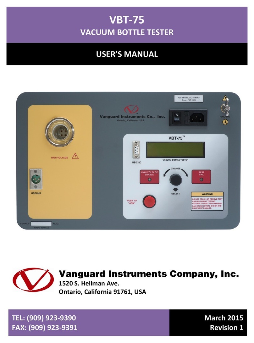
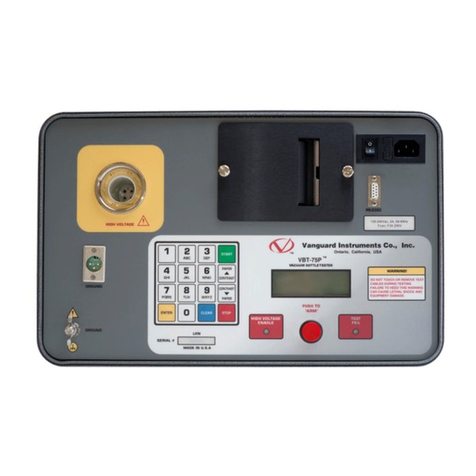
Vanguard Instruments VBT-75 S2 User manual

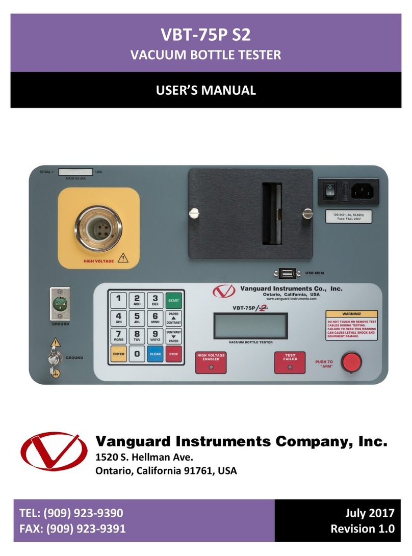
VBT-75 S2
VACUUM BOTTLE TESTER
USER’S MANUAL
Vanguard Instruments Company, Inc.
1520 S. Hellman Ave.
Ontario, California 91761, USA
TEL: (909) 923-9390
FAX: (909) 923-9391
July 7, 2017
Revision 1

VBT-75 S2 USER’S MANUAL REV 1
i
SAFETY SUMMARY
FOLLOW EXACT OPERATING PROCEDURES
Any deviation from the procedures described in this operator’s manual may create one or more safety hazards,
damage the VBT-75 S2, or cause errors in the test results; Vanguard Instruments Co., Inc. assumes no liability for
unsafe or improper use of the VBT-75 S2. The following safety precautions must be observed during all phases of
test set up, test hookups, testing, and test-lead disconnects.
SAFETY WARNINGS AND CAUTIONS
This device shall be used only by trained operators. All circuit breakers under test shall be off line and fully
isolated.
SERVICE AND REPAIR
• Do not install substitute parts or perform any unauthorized modification to any VBT-75 S2 test unit.
• Repairs must be performed only by Vanguard Instruments Company factory personnel or by an authorized
repair service provider. Unauthorized modifications can cause safety hazards and will void the manufacturer’s
warranty.
EQUIPMENT RATINGS
IP Rating: The enclosure for the VBT-75 S2 has an IP rating of 32.
Pollution Degree: The VBT-75 S2 has a pollution rating of 2.
Operating Voltage: The VBT-75 S2 is rated for use with an operating voltage of 120V or 240V, auto-ranging ±10%
of selected voltage.
Power Cord: The VBT-75 S2 is supplied with a 16 AWG, 16A power cord with a NEMA 5-15P plug. Replacement
cable shall have the same or better rating and is available through the manufacturer.
VENTILATION REQUIREMENTS
The VBT-75 S2 must be operated with the enclosure lid open.
SAFETY SYMBOLS
Indicates that caution should be exercised
OR
Indicates location of chassis ground terminal
CLEANING
To clean the VBT-75 S2:
• Disconnect all cables and turn the unit off.
• Use a soft, lint-free cloth to wipe all surfaces clean.
• Avoid getting moisture in openings and connectors.
• Don't use any cleaning products or compressed air.
REV 1 VBT-75 S2 USER’S MANUAL
ii
TABLE OF CONTENTS
CONVENTIONS USED IN THIS DOCUMENT ....................................................................... 1
1.0 INTRODUCTION .................................................................................................................... 2
1.1 General Description and Features ................................................................................... 2
1.2 Technical Specifications ................................................................................................... 3
1.3 VBT-75 S2 Controls and Indicators .................................................................................. 4
2.0 CABLE CONNECTIONS .......................................................................................................... 6
3.0 OPERATING PROCEDURES ................................................................................................... 7
3.1 Set the Date and Time ..................................................................................................... 7
3.2 Changing the LCD Screen Contrast .................................................................................. 8
3.3 Performing a Test ............................................................................................................. 9
3.4 Updating Firmware ........................................................................................................ 11
LIST OF TABLES
Table 1. VBT-75 S2 Technical Specifications ................................................................................... 3
Table 2. Functional Descriptions of VBT-75 S2 Controls and Indicators ........................................ 5
LIST OF FIGURES
Figure 1. VBT-75 S2 Controls and Indicators .................................................................................. 4
Figure 2. VBT-75 S2 Connection Diagram ....................................................................................... 6

REV 1
V
1
This doc
u
•
A ke
y
•
Scre
e
• VBT-
7
Note
exa
m
• War
n
W
A
• Imp
o
N
[R
V
BT-75 S2
U
C
u
ment uses
y
or switch
o
e
n and men
u
7
5 S2 LCD s
c
that the sel
m
ple above).
n
ing messag
e
A
RNING
W
a
o
rtant notes
OTE
No
UN TEST]
SETUP
CABLE VT
U
SER’S MAN
C
ONVEN
T
t
he followi
n
o
n the VBT-
7
u
names are
c
reen outpu
t
ected item
o
e
s are indic
a
a
rning mes
s
are indicat
e
te details
07/06
/
11:03:
G: 0V
UAL
T
IONS U
S
n
g conventi
o
7
5 S2 is indi
c
referenced
t
is shown a
s
o
n the scre
e
a
ted as:
s
age
e
d as:
/
17
05
S
ED IN T
H
o
ns:
c
ated as
[K
E
as “SCREEN
s
:
e
n is enclose
H
IS DOC
U
E
Y]
and
[S
W
/MENU NA
M
d in bracke
t
U
MENT
W
ITCH]
.
M
E”.
t
s ("[RUN TE
S
S
T]", in the

VBT-75 S2 USER’S MANUAL REV 1
2
1.0 INTRODUCTION
1.1 General Description and Features
The VBT-75 S2 is Vanguard's second generation microprocessor-based, portable, 75kV dc
vacuum bottle tester. This lightweight, portable tester is designed for testing circuit-breaker
vacuum bottles in the field and at the shop.
Test voltages can be selected from 10 kV dc to 75 kV dc in 5 kV steps. The high-voltage test time
can be set from 5 seconds to 2 minutes. The test voltage is raised to the selected voltage and
held for the test time duration. The test voltage and leakage current are displayed on the LCD
during testing. After the test time duration has elapsed and the leakage current did not pass the
pre-set value of 100 µA, 200 µA, or 300 µA, the test voltage is returned to zero and a "Pass"
message is displayed. If a flash-over condition occurs, such as bottle failure, the test voltage is
immediately turned off, a “Failure” message is displayed on the LCD screen, and the “TEST FAIL”
LED light on the unit is also illuminated.
The presence of high voltage is indicated by an audible tone and an illuminated “HIGH
VOLTAGE” LED light. For additional operator safety, an “ARM” switch must be held down during
testing.
The VBT-75 S2 features a back-lit LCD screen (20 characters by 4 lines) that is viewable in both
bright sunlight and low-light levels. A turn-and-press knob is used to control the unit. The VBT-
75 S2's firmware can be updated in the field via the unit's built-in USB Flash drive port.
The VBT-75 S2 is furnished with a 10-foot test cable that is terminated with a quick-disconnect
test clip. A transportation case is also included.

REV 1
V
3
1.2
T
PHY
S
OU
T
NO
V
BT-75 S2
U
T
echnical
S
S
ICAL SPECI
F
INP
U
OUTPU
T
T
PUT RIPPLE
DISCH
A
IN
D
FIRMWAR
E
ENV
I
HUMI
D
ALTIT
U
SHIP
P
W
TE
The
a
tem
p
U
SER’S MAN
S
pecificati
o
Table
TYPE
P
F
ICATION
S
D
W
U
T POWER
9
T
VOLTAGE
1
VOLTAGE
3
A
RGE TIME
M
DISPLAY
B
V
CONTROL
S
D
ICATOR
S
F
2
H
E
UPDATE
S
f
i
n
I
RONMENT
O
S
D
ITY (MAX)
9
U
DE (MAX)
2
CABLES
o
r
P
ING CASE
S
W
ARRANTY
O
a
bove specif
p
erature of
2
UAL
o
ns
1. VBT-75 S
2
P
ortable 75 kV
D
imensions: 1
W
eight: 10 lbs
9
0 – 240 Vac,
2
1
0kV – 75 kV
d
3
% max
M
aximum disc
h
B
ack-lit LCD (
2
V
iewable in bri
g
S
ingle turn-an
d
F
ailure Indica
t
2
00 μA, or 300
H
igh Voltage I
irmware can b
e
n
terface
O
perating: -10˚
S
torage: -30˚
C
9
0% RH @ 40˚
2
000m (6562 f
t
o
ne 10-foot (3.
0
r
eturn cable, o
n
S
hipping case
i
O
ne year on p
a
ications are
2
5°C (77°F).
2
Technical
S
vacuum bottle
7”W x 10.5”H
x
. (4.53 Kg)
2
A, 50/60 Hz
d
c in 5 kV step
s
h
arge time for i
2
0 characters x
g
ht sunlight an
d
-press knob
t
o
r
: LED illum
i
μA (program
m
ndicator: LE
D
e
updated in t
h
to 50˚ C (15˚
t
C
to 70˚ C (-22˚
C (104˚ F) no
t
) to fully safet
y
0
5m) high-volt
a
n
e ground cabl
i
s included
a
rts and labor
valid at no
m
Specificatio
n
S
pecificatio
n
tester
x
6.5” D (42.7
s
; accuracy: 1.
5
nternal high v
o
4 lines);
d lo
w
-light lev
e
i
nates when te
m
able)
D
illuminates w
h
h
e field via the
t
o +122˚ F);
to +158˚ F)
n-condensing
y
specification
s
a
ge cable, one
e, one power
c
m
inal opera
t
n
s may cha
n
n
s
cm x 26.9 cm
x
5
%
o
ltage is 3 sec
o
e
ls
st current exc
e
h
en high volta
g
unit's built-in
U
s
10-foot (3.05
m
c
ord
t
ing voltage
a
n
ge without
x
16.5 cm)
o
nds
e
eds 100 μA,
g
e is present
U
SB Flash driv
e
m
) high voltag
e
a
nd at a
prior notice
e
e
.

VBT-75 S2 USER’S MANUAL REV 1
4
1.3 VBT-75 S2 Controls and Indicators
The VBT-75 S2’s controls and indicators are shown in Figure 1 below. A leader line with an index
number points to each control and indicator, which is cross-referenced to a functional
description in Table 2. The table describes the function of each item on the control panel. The
purpose of the controls and indicators may seem obvious, but users should become familiar
with them before using the VBT-75 S2. Accidental misuse of the controls will usually cause no
serious harm. Users should also be familiar with the safety summary found on the front page of
this User’s Manual.
Figure 1. VBT-75 S2 Controls and Indicators

REV 1 VBT-75 S2 USER’S MANUAL
5
Table 2. Functional Descriptions of VBT-75 S2 Controls and Indicators
Item
Number Panel Markings Functional Description
1 HIGH VOLTAGE High voltage cable connector
2 USB MEM USB flash drive interface for firmware updates
3 Back-lit LCD screen (4 lines x 20 characters).
Viewable in bright sunlight and low-light levels.
4
120/240 Vac, 2A,
50-60 Hz
F3AL 250V
Input power connector with built-in fuse holder and power switch
5 GROUND VBT ground stud. Connect ground stud to substation ground using the provided
cable.
6 TEST FAILED Test failure indicator. This indicator turns on if the test current exceeds the
present current threshold (100, 200, or 300 μA).
7 PUSH TO
"ARM"
Arm switch; press and hold during testing.
8 CHANGE VBT turn-and-press control knob.
9 HIGH VOLTAGE
ENABLED
This indicator turns on when high test voltage is present at the test leads.
10 GROUND High voltage return cable connector

2.0
C
The VBT
-
voltage
r
to the va
WARNIN
G
C
ABLE C
O
-
75 S2 come
r
eturn cable
.
cuum bottl
e
G
• To pr
o
conn
e
• The c
i
• The v
a
O
NNEC
T
s furnished
.
Both cable
s
e
being test
e
o
tect the V
B
e
ct the unit'
s
i
rcuit break
e
a
cuum bottl
Fig
u
T
IONS
with one 10
s
are termin
e
d. A typical
B
T-75 S2 aga
s
ground st
u
e
r must be
o
e under tes
t
u
re 2. VBT-7
5
-foot (3.05
m
ated with a
l
cable conn
e
inst static d
i
u
d to the su
b
o
ff-line and
c
t
should be
i
5
S2 Connec
t
VBT-75
m
) high volt
a
l
ligator cla
m
e
ction is sh
o
i
scharge in t
b
station gro
u
c
ompletely i
s
i
n the OPEN
t
ion Diagra
m
S2 USER’S
M
a
ge cable an
d
m
ps that are
o
wn in Figur
e
he substati
o
u
nd.
s
olated.
position.
m
M
ANUAL
R
d
one 10-fo
o
used to con
n
e
2 below.
o
n, always
R
EV 1
6
o
t
n
ect

REV 1 VBT-75 S2 USER’S MANUAL
7
3.0 OPERATING PROCEDURES
3.1 Set the Date and Time
Follow the steps below to set the date and time for the VBT-75 S2's internal clock:
a. Start from the "START-UP" menu:
Turn the [CONTROL KNOB] until the SETUP option is enclosed in brackets as shown
below:
Press the [CONTROL KNOB].
b. The following screen will be displayed:
The SetTime option should be enclosed in brackets. Press the [CONTROL KNOB].
c. The following screen will be displayed:
Turn the [CONTROL KNOB] to select the first digit of the month and then press the
[CONTROL KNOB]. The cursor will move over to the second digit of the month.
Continue this process to enter the date and time. When you press the [CONTROL
KNOB] for the last time to set the second digit of the current minute, the date and
time will be set and you will be returned to the "START-UP" menu.
ENTER
MM-DD-YY HH:MM:SS
_
[SetTime ] LANGUAGE
LCD CONT EXIT
CABLE VTG: 0V
RUN TEST 07/06/17
[ SETUP ] 11:03:05
CABLE VTG: 0V
[RUN TEST] 07/06/17
SETUP 11:03:05
CABLE VTG: 0V

VBT-75 S2 USER’S MANUAL REV 1
8
3.2 Changing the LCD Screen Contrast
Follow the steps below to adjust the VBT-75 S2's LCD screen contrast:
a. Start from the "START-UP" menu:
Turn the [CONTROL KNOB] until the SETUP option is enclosed in brackets as shown
below:
Press the [CONTROL KNOB].
b. The following screen will be displayed:
Turn the [CONTROL KNOB] until the LCD CONT option is enclosed in brackets as
shown below:
Press the [CONTROL KNOB].
c. The following screen will be displayed:
Turn the [CONTROL KNOB] clock-wise or counter-clockwise to adjust the screen
contrast. Press the [CONTROL KNOB] when the contrast is to your liking. You will be
returned to the "START-UP" menu.
LCD CONTRAST
to ADJUST
"PRESS to EXIT"
SetTime LANGUAGE
[LCD CONT] EXIT
CABLE VTG: 0V
[SetTime ] LANGUAGE
LCD CONT EXIT
CABLE VTG: 0V
RUN TEST 07/06/17
[ SETUP ] 11:03:05
CABLE VTG: 0V
[RUN TEST] 07/06/17
SETUP 11:03:05
CABLE VTG: 0V

REV 1 VBT-75 S2 USER’S MANUAL
9
3.3 Performing a Test
Follow the steps below to perform a test:
a. Start from the “START-UP” menu:
The RUN TEST option should be enclosed in brackets. Press the [CONTROL KNOB].
b. The following screen will be displayed:
Turn the [CONTROL KNOB] to select the desired test duration and then press the
[CONTROL KNOB].
c. The following screen will be displayed:
Turn the [CONTROL KNOB] clock-wise or counter-clockwise to increase or decrease
the test voltage by 5 KV increments, respectively (10 KV to 75 KV). When the desired
test voltage is displayed, press the [CONTROL KNOB].
d. The following screen will be displayed:
Turn the [CONTROL KNOB] to select the flash-over threshold (300 μA, 200 μA, or
100 μA), and then press the [CONTROL KNOB].
[ 300 μA ] 200 μA
100 μA ABORT
ENTER TEST VOLTAGE:
(10 to 75)
10 KV
[ 5 Sec ] 10 Sec
30 Sec 60 Sec
2 Min ABORT
[RUN TEST] 07/06/17
SETUP 11:03:05
CABLE VTG: 0V

VBT-75 S2 USER’S MANUAL REV 1
10
e. The following summary screen will be displayed:
If you need to make changes, turn the [CONTROL KNOB] either clock-wise or
counter-clockwise and you will be returned to step b.
If the test parameters are correct, press the [CONTROL KNOB].
f. The following screen will be displayed:
Press the red [PUSH TO "ARM"] switch.
g. The VBT-75 S2 will initiate the test and start the timer based on the test duration
selected. The screen will be updated with the test voltage and the leakage current as
shown below:
h. After the test time duration has elapsed, the test results will be displayed. If the leakage
current did not pass the preset value set in step d, the test voltage is returned to zero
and a "PASS" message is displayed as shown below:
However, if a flash-over condition occurred, such as bottle failure, the test voltage is
immediately turned off and a "FAIL" message is displayed as shown below:
The "TEST FAIL" LED on the front panel will also be illuminated to indicate a test failure.
Press the [CONTROL KNOB] to return to the "START-UP" menu.
TEST COMPLETE
>>>FAIL<<
TEST COMPLETE
>>>PASS<<
TEST IN PROGRESS
55KV 59.31 μA
Time: 00:04
PRESS RED SWITCH
TO START TEST
TEST PARAMETERS
75KV 5Sec 300 μA
"PRESS" IF OKAY

REV 1 VBT-75 S2 USER’S MANUAL
11
3.4 Updating Firmware
The VBT-75 S2' firmware is user-upgradeable. The firmware version is displayed on the LCD
screen during the start-up sequence when the unit is powered one. Follow the steps below to
download and install the latest VBT-75 S2 firmware:
a. Visit the Vanguard web site at http://www.vanguard-instruments.com. Login to your
account using the login form on the left side of the page:
If you do not have an account, click on the "Create new account" link below the login
area to create your free account. Please note that your account will need to be
approved first before it can be used to download any software or firmware. This is
usually done within 30 minutes of creating your account.
b. After logging in to your account, hover your mouse over the "Downloads" link at the top
of the page and click on the "Software/Firmware Downloads" link:
c. All Vanguard products will be listed along with any compatible firmware and software.
Scroll down the page to find the VBT-75 S2 listing and then click on the firmware link to
save the firmware file.
d. Once the download is complete, navigate to the folder where the file was downloaded
and extract the compressed ZIP file (you may need to use a ZIP extraction application
such as WinZip, 7-Zip, etc.). Once extracted, you should see the file "vbt75s2.hex". This
is the firmware file.

e. C
f.
W
d
g.
W
h. T
fi
p
opy the file
NOTES
W
ith the VB
T
rive port.
W
hile holdin
g
he VBT-75
S
rmware up
g
rocess is co
m
"vbt75s2.h
e
• Please
u
then d
e
• We rec
o
T
-75 S2 turn
e
g
down the
[
S
2 will go th
r
g
rade proce
s
m
plete.
e
x" to the ro
u
se an emp
t
e
lete them f
r
o
mmend us
e
d off, inser
t
[
CONTRO
L
r
ough the in
i
s
s. The "STA
ot folder of
t
y flash driv
e
r
om the dri
v
ing a flash d
t
the USB Fl
a
L
KNOB]
,
t
i
tial starting
RT-UP" me
n
VBT-75
a USB Flash
e
. Please ba
c
v
e.
rive with a
c
a
sh drive in
t
t
urn on the
p
sequence a
n
u will be di
s
S2 USER’S
M
drive.
c
kup any ex
i
c
apacity of
8
t
o the VBT-7
p
ower.
nd then will
s
played onc
e
M
ANUAL
R
i
sting files a
n
8
GB or less.
5 S2's USB
F
start the
e
the upgra
d
R
EV 1
12
n
d
F
lash
d
e

1520 S. Hellman Ave • Ontario, CA 91761 • USA
Phone: 909-923-9390 • Fax: 909-923-9391
www.vanguard-instruments.com
Copyright © 2017 by Vanguard Instruments Company, Inc.
VBT-75 S2 User’s Manual • Revision 1.0 • July 27, 2017 • TA
Table of contents
Other Vanguard Instruments Test Equipment manuals

Vanguard Instruments
Vanguard Instruments EZCT Use and care manual

Vanguard Instruments
Vanguard Instruments MCCB-500 User manual

Vanguard Instruments
Vanguard Instruments EZCT User manual

Vanguard Instruments
Vanguard Instruments EZCT-2000C User manual

Vanguard Instruments
Vanguard Instruments RFD-200 2 Series User manual

Vanguard Instruments
Vanguard Instruments EZCT Manual

Vanguard Instruments
Vanguard Instruments EZCT S2A User manual

Vanguard Instruments
Vanguard Instruments VBT-75 User manual

Vanguard Instruments
Vanguard Instruments CVT-765 User manual

Vanguard Instruments
Vanguard Instruments EZCT-2000A User manual