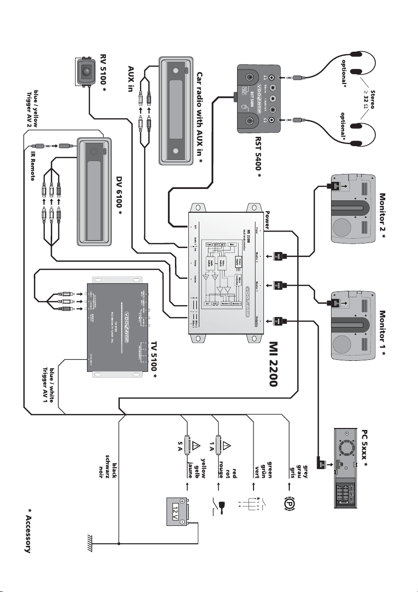
Electrical connections, Fig. 2
☞Route all wiring with care. For wiring details, refer to the connection diagram on the back
cover page and to the following table.
☞Do not cut non-assigned wires. Instead, wind them together and secure to one side. They
may be required for retrofitting additional functions.
Power supply cable
Wire colour Connection
Yellow + 12 V permanent positive (must be rated for at least 4 A.)
Red + 12 V ACC / ignition positive (without switch-off on starting engine)
Black Battery negative (body)
Blue/white + 12 V remote input AV1 (activates the audio / video input 1)
Blue/yellow + 12 V remote input AV2 (activates the audio / video input 2)
Green + 12 V reversing signal (reversing light positive), active at + 12 V (active high)
Grey + 12 V parking brake signal, active at earth potential (active low)
AOnly connect electrical signals to suitable connecting points in the vehicle.
AFor direct connection of permanent positive (yellow lead) to the battery, the fuse must be no
further than 10 - 15 cm from the positive terminal of the battery. If it is necessary to extend the
positive lead, an additional 10 A fuse must be provided close to the battery (max. distance 10 -
15 cm). Failure to do so may result in a wiring fire hazard.
■12 V permanent positive (yellow):
☞Connect yellow wire to a suitable connector with 12 V permanent positive.
AThis connection should be rated for a current of at least 4 amps.
■12 V ignition / ACC / accessory contact (red):
☞Connect red wire to a suitable 12 V circuit switched through the ACC ignition key contact.
■Battery negative (black)
☞Connect black wire to a suitable earthing point on the vehicle body.
■12 V remote inputs AV1 and AV2
In order to ensure full functionality of the MI 2200, the external video sources should be
provided with a 12 V remote control output.
a) Remote input AV1 (blue/white):
☞Connect blue/white wire to 12 V remote control output of the video source to be
connected to the AV1 input of the MI 2200.
b) Remote input AV2 (blue/yellow):
Connect blue/yellow wire to 12 V remote control output of the video source to be connected
to the AV2 input of the MI 2200.
■Reversing signal (green)
☞Connect green wire to a suitable reversing signal point (positive lead of reversing light).
■Parking brake signal (grey)
☞Connect grey wire to a suitable parking brake signal point.
If the MI 2200 is used with both monitors for the rear passengers, the grey wire should be
permanently connected to earth.
INSTALLATION INSTRUCTIONS
8