manuals.online logo
Brands
  1. Home
  2. •
  3. Brands
  4. •
  5. Vectaire
  6. •
  7. Fan
  8. •
  9. Vectaire VX Series User manual

Vectaire VX Series User manual

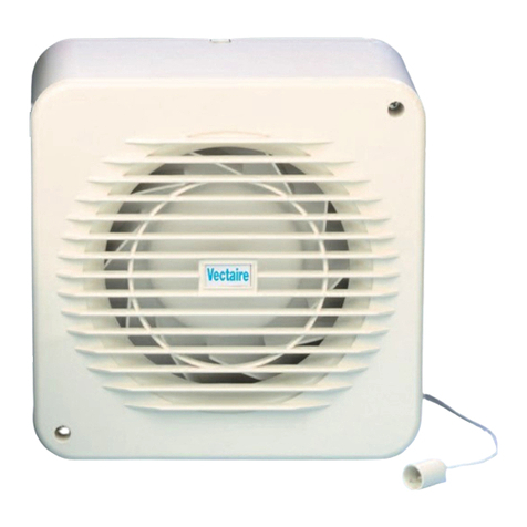
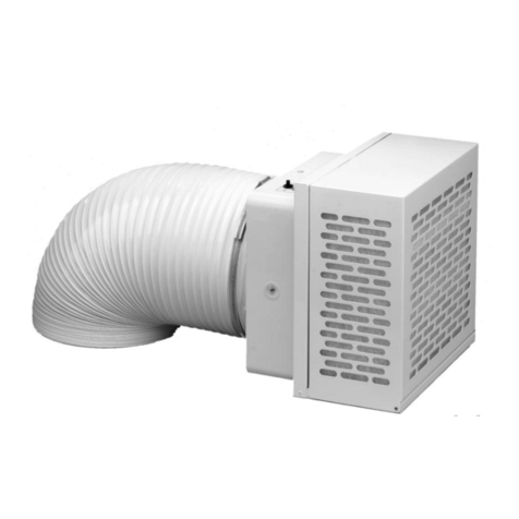
“VX” RANGE
Window/Wall Axial Fans for Domestic/Commercial Use
NOTE FOR INSTALLER:
THIS MANUAL MUST ALWAYS BE READILY AVAILABLE
INSTRUCTION MANUAL
Vectaire Ltd.
Lincoln Road, Cressex Business Park, High Wycombe
Buckinghamshire , HP12 3RH - UK
Tel. +44 (0) 1494 522333 - Fax . +44 (0) 1494 522337
VX15/6M VX23/9M VX30/12AR
VX15/6A VX23/9MR
VX23/9AR
MODEL
SIZE APPLICATION FEATURES EXTRACT
CAPACITY SUPPLY
VX15/6M 6”/15cm Pull cord operation - extract only 220 m³/hr
61 l/sec 230v, 50Hz, 20w
VX15/6A 6”/15cm Automatic - extract only - neon indicator to show
when fan is working - silent, slow moving, delay
action shutters
220 m³/hr
61 l/sec 230v, 50Hz, 20w
VX23/9M 9”/23cm Pull cord operation -
extract (or intake) only 750 m³/hr
208 l/sec 230v, 50Hz, 42w
VX23/9MR 9”/23cm Pull cord operation - reversible 750 m³/hr
208 l/sec 230v, 50Hz, 42w
VX23/9AR 9”/23cm Automatic - reversible - with 5 speed controller -
neon indicator to show when fan is working - silent,
slow moving, delay action shutters
750 m³/hr
208 l/sec 230v, 50Hz, 42w
VX30/12AR 12”/30cm Automatic - reversible - with 5 speed controller -
neon indicator to show when fan is working - silent,
slow moving, delay action shutters
1,400 m³/hr
389 l/sec 230v, 50Hz, 102w
For domestic
or commercial
installations
For wall, window or
ceiling mounting
(with appropriate Kit)
GENERAL PRECAUTIONS
IT IS RECOMMENDED THAT YOU READ THE FOLLOWING INSTRUCTIONS VERY CAREFULLY BEFORE USING THE PRODUCT. THE
MANUFACTURER WILL NOT BE HELD RESPONSIBLE AND DECLINES ANY AND ALL LIABILITY FOR DAMAGE CAUSED TO PERSONS OR
PROPERTY DUE TO IMPROPER USE WITH REFERENCE TO THE PRECAUTIONS OUTLINED IN THIS MANUAL.
The manual explains how to install correctly, use and carry out maintenance on the product. Following these instructions will ensure that the
product will be electrically and mechanically reliable and will extend its working life.
· Do not use this product for any purpose other than that for which it was designed and as illustrated herein.
· When removing the product from its packaging, make sure that it has not been damaged. If in doubt, contact immediately your supplier.
· Do not leave packing material within the reach of children or unskilled people. Do not dump any hazardous parts into the environment
(polystyrene, plastic, polypropylene, etc.).
· If the product is dropped or badly knocked, contact immediately qualified personnel (authorised dealer, service centre or manufacturer) to check
that the product operates correctly.
· The use of any electrical device requires compliance with some basic rules which are listed below:
- do not touch the device with moist or wet parts of the body (hands, feet).
- do not allow the product to be operated by children or unskilled people.
· Connect the product to the mains electricity supply or electrical outlet only if:
- your electrical voltage and frequency corresponds to those shown on the rating label.
- the capacity of your electricity supply is sufficiently powerful to operate the product at its maximum power.
If not, contact a professional electrician.
· It is recommended that the product is switched off when not in use.
· Before carrying out any maintenance or cleaning, switch off the product and disconnect it from the mains electricity supply.
· If a fault, malfunction or anomaly of any type occurs, make the fan inoperative (by turning off the switch and by disconnecting it from the mains
electricity supply) and immediately contact qualified personnel.
Always request original spare parts to effect any repairs.
· If the product needs to be removed, turn off the mains supply circuit-breaker and then disconnect the fan.
Place the device in a safe location away from children and/or unskilled people.
· All electrical connections must comply with current IEE wiring regulations.
SPECIAL PRECAUTIONS
. The product is professionally manufactured and complies with the current standards regarding electrical equipment.
· The fans comply with BSEN60335; with the Low Voltage Directive; with EC Directive EMC 89/336 for the Suppression of Radio Interference.
· Do not use the product at an ambient temperature higher than 40 °C (104 °F).
· Do not allow the product to be exposed to atmospheric agents (rain, sun, snow, etc.).
· Possible product applications are indicated in the attached illustrations.
· Do not place the fan or relative parts in water or liquids, except where indicated in the cleaning and maintenance section.
· When cleaning or performing routine maintenance, check the condition of the fan.
· To avoid the risk of fire, do not use the product in the presence of inflammable substances or vapours such as alcohol, insecticides, gasoline, etc.
· The air or fumes being extracted must be clean and free from greasy particles, soot, chemical and corrosive agents, inflammable or explosive
mixes (If these substances are treated, contact an authorised dealer for specific range of explosion-proof products).
· The product must be installed by professionally qualified personnel. Incorrect installation can cause damage to people, animals or
property, for which the manufacturer cannot be held liable.
· The product must be connected to the electricity supply via a fixed wired and fused (3 amp) spur incorporating a double pole switch with contact
openings of at least 3 mm.
· To ensure optimum operation, do not block the air intake and exit vents.
· Ensure that any ducting used is free of blockages.
· For optimum operation, ensure that the product is installed at a minimum height of 2.30 m above the ground.
· The room where the fan is located must be adequately ventilated to ensure correct operation.
· If the product is sited in a room containing a fuel burning appliance which is not of the balanced flue type, the installer must ensure that air
replacement is adeguate both for the fan and the fuel burning appliance.
· The fan should not be used as an activator for water heaters, stoves, etc.
· The fan must not exhaust into ducts designed to evacuate fumes from the combustion in stoves or other combustion-powered devices.
· The fan must have a single duct (for its exclusive use) or exhaust directly outside.
RANGE
1. GENERAL INFORMATION
1.1 All automatic (A) fans incorporate a neon indicator to show when the fans are operating.
1.2 The fans are suitable for installation into a window, wall, ceiling, panel or sealed double glazed units (with the appropriate accessories).
1.3 The fan is a fixed appliance, and the electrical supply must therefore be by a fixed wired and fused (3 amp) spur incorporating a double pole
switch with contact openings of at least 3 mm. The type of cable to be used is shown in Fig. 6.
1.4 Your fan is double insulated and does not require earthing.
1.5 It is recommended that the installation be carried out by a qualified electrician.
1.6 The printed circuit board in these fans has been protected to make it compatible with the majority of fluorescent fittings available on the market
today. However, it is impossible to be aware of all the new products introduced. We suggest therefore that you contact your supplier to
establish the compatibility of the fluorescent fitting you intend to use.
2. INSTALLATION
2.1 Cut a hole for the fan exhaust outlet in the required position, sized as follows:
6”/15cm models - 184-188mm dia
9”/23cm models - 254-258mm dia
12”/30cm models - 324-329mm dia.
2.2 Remove the front cover (No 1) by pressing the black buttons on each side of the fan (or unscrewing the buttons on the VX30/12AR).
2.3 Unscrew the 4 screws (No 2) and remove the motor/fan assembly (No 3).
2.4 Remove outside grille (No 15) by unscrewing the brass slothead nuts (No 4) recessed in the main casing (No 5).
2.5 WINDOW INSTALLATION (FIG 1)
A Suitable for window thicknesses up to 20mm. In case of double glazed window use Double Glazing Kit (FIG 1A).
B Position the outside grille (No 15) on the outside of the window, line up the main casing (No 5) and tighten into positionby screwing
back the slothead nuts (No 4) .
2.6 WALL MOUNTING INSTALLATION (FIG 3)
A wall vent kit consisting of an additional wall plate and wall rods is required for this installation.
A Fix wall rods (No 10) to the outside grille (No 15) using M5 brass nuts (No 12 - 4 off for 6”/15cm and 9”/23cm models and 6 off for
VX30/12AR).
B Insert the wall plate (No 7) over the extension rods (trough holes closest to the spigot) ensuring that the spigot is protruding
into the hole.
C If desired, fix a wall sleeve (not supplied) over the wall rods to mate with the spigots on the outside grille (No 15) and the wall
plate (No 7).
D Line up the main casing (No 5) with the wall rods and tighten into position with the brass slothead nuts (No 4).
2.7 WALL FIXING INSTALLATION (FIG 4)
A Fix the outside grille (No 15) to the outside wall using the screws (No 16) and wall plugs (No 14) supplied.
B Using the the main casing (No 5) as a template (holes closest to the corners) drill four suitable holes and place the wall plugs (No 9).
C Fix the wall plate (No 7) to the main casing using the bolts (No 8) and the brass slothead nuts (No 4) (through holes closest to the
spigot).
D Fix the wall plate and the main casing to the inside wall loosening the screws (No 6) into the four drilled holes ensuring that
the spigot is protruding into the wall.
2.8 CEILING OR DOUBLE WINDOW INSTALLATION (FIG 2)
A ceiling kit or a double window kit consisting of 2 additional wall plates and ducting is required for this installation.
A Cut a hole (see 2.1) in both the ceiling and the outside wall (or in both the windows).
B Position the outside grille (No 15) on the outside surface of the wall (or outer window), line up the additional wall plate (No 13) on the
inside surface of the wall with its spigot facing inwards and fix into position with M5 brass nuts (No 12).
C With the wall plate (No 7) on the other (loft) side of the ceiling (or inner window), and with its spigot pointing away from the ceiling, fix
the main casing of the fan (No 5) to the wall plate (No 7) with the fan casing inside the room using the bolts (No 8) and the brass
slothead nuts (No 4) (trough holes closest to the spigot).
D Fix ducting between the two wall plates.
2.9 Manually check that the fan impellor rotates easily.
2.10 Feed in wire (2 core for fans without speed con troller and 4 core for fans with speed controller) through the black grommet on the top of the
fan and connect the fan following WIRING INSTRUCTIONS.
2.11 Reposition the motor/fan assembly (No 3), tightening into position with 4 off screws (No 2).
2.12 Ensure the front cover louvres are in the open position before replacing the front cover.
3. WIRING INSTRUCTIONS
3.1 Ensurethat the mains electricalsupply is switched off duringtheinstallationofthefixed wiringspur.
3.2 Readcarefully"General Information" above.
3.3 Connectasshown intheWiringDiagrams(FIG5).
4. TESTING
4.1 When the installation is complete, switch on the electricity supply.
4.2 Pull cord models: check that operating the pull cord will alternately start/stop the fan and open/close the shutters. With the fan operating,
check that an adequate amount of air is being exhausted (ie no blockages are present) and the fan noise is not excessive.
4.3 VX15/6A: check as above using the remote switch to start the fan.
4.4 Automatic models with speed controller:
A With speed controller rotary switch S3 set to position 1 (slowest speed),
set switch S1(on/off switch) to position1. Check the following:
- Switch S1 illuminates
- The neon on the fan illuminates
- The front cover shutters silently open (this will take 30-45 seconds
and there is a delay before they start to open).
B Turn switch S3 clockwise to position 2 and note that the fan speed increases.
Repeat for positions 3, 4 and 5. With S3 in position 5
(highest fan speed) check that the fan noise is not excessive.
C With S3 in position 5, select another position on switch S2 and
note that the direction of the fan impeller reverses
D Select position 0 on switch S3 and check that the fan becomes stationary,
but the shutters remain open
E Switch S1 to position 0 (off) and note that the front cover shutters slowly
close (taking approximately 1-2 minutes to close fully.
INSTALLATION
Vectaire Ltd reserves the right to alter its products as part of its policy of continuous development. E&O.E
1 Front Cover
2 Screws
3 Motor/Fan Assembly
4 Brass Slothead Nuts
5 Main Casing
6 Wall Fixing Screws
7 Wall Plate
8 Wall Plate Fixing Screws
9 Wall Plugs
10 Wall Rods
11 Double Window Spacer
12 Brass Slothead Screws
13 Window Plate
14 Wall Plugs
15 External Grille - Inner
16 Wall FixingScrews
17 External Grille - Outer
18 Grille Fixing Screws
5a VX23/9AR and VX30/12AR with speed controller
5b VX23/9AR and VX30/12AR for extract only
5c VX23/9AR and VX30/12AR for intake only
5d VX23/9AR and VX30/12AR with reversibility
switch (not supplied)
5e VX23/9M for extract only
5f VX23/9M for intake only
5g VX23/9MR with reversible switch (not supplied)
5h VX15/6M
5m VX15/6A
5n VX23/9AR and VX30/12AR terminal block
5n
6
1 2
3 4
5a
5b 5c 5d
5e 5f 5g
5h 5m
Hole diameters:
6”/15cm: 184-188mm
9”/23cm: 254-258mm
12”/30cm: 324-329mm
The exterior of the fan may be cleaned with a dry cloth. The interior of the fan should be cleaned occasionally.
First, disconnect from the mains electrical supply, remove the front cover, and then the motor/fan assembly as described in sections 6b and 6c.
The front cover may be washed with a mild detergent, but the fan body must be wiped with a clean, dry cloth.
ON NO ACCOUNT MUST THE MOTOR BE IMMERSED IN WATER OR STRONG SOLVENTS USED.
MAINTENANCE AND CLEANING

This manual suits for next models

5

Other Vectaire Fan manuals

Vectaire ELEGANCE EL1003 User manual

Vectaire

Vectaire ELEGANCE EL1003 User manual

Vectaire ELP2204 User manual

Vectaire

Vectaire ELP2204 User manual

Vectaire WHHR100/90DC-B Plus User guide

Vectaire

Vectaire WHHR100/90DC-B Plus User guide

Vectaire ELEGANCE EL1203 User manual

Vectaire

Vectaire ELEGANCE EL1203 User manual

Vectaire PPF4 Assembly instructions

Vectaire

Vectaire PPF4 Assembly instructions

Vectaire MBOX204/2 Assembly instructions

Vectaire

Vectaire MBOX204/2 Assembly instructions

Vectaire ELIX 1003 User manual

Vectaire

Vectaire ELIX 1003 User manual

Vectaire WHHR100/90DC User manual

Vectaire

Vectaire WHHR100/90DC User manual

Vectaire RMF 100 User manual

Vectaire

Vectaire RMF 100 User manual

Vectaire ELPREX 16 User manual

Vectaire

Vectaire ELPREX 16 User manual

Vectaire ELEGANCE 16 User manual

Vectaire

Vectaire ELEGANCE 16 User manual

Vectaire X-MART XM10 User manual

Vectaire

Vectaire X-MART XM10 User manual

Vectaire MF100T User manual

Vectaire

Vectaire MF100T User manual

Vectaire ELIX 1003 User manual

Vectaire

Vectaire ELIX 1003 User manual

Vectaire ELEGANCE EL1003DT User manual

Vectaire

Vectaire ELEGANCE EL1003DT User manual

Vectaire SFK10/4 User manual

Vectaire

Vectaire SFK10/4 User manual

Vectaire Purge-Box 100 User manual

Vectaire

Vectaire Purge-Box 100 User manual

Vectaire eSmile User guide

Vectaire

Vectaire eSmile User guide

Vectaire AS Series User manual

Vectaire

Vectaire AS Series User manual

Vectaire ELIX 1003 User manual

Vectaire

Vectaire ELIX 1003 User manual

Vectaire RA10 User manual

Vectaire

Vectaire RA10 User manual

Vectaire MBOX 125/2DC User manual

Vectaire

Vectaire MBOX 125/2DC User manual

Vectaire PPF9 Assembly instructions

Vectaire

Vectaire PPF9 Assembly instructions

Vectaire Microbox 125/2DC-B User manual

Vectaire

Vectaire Microbox 125/2DC-B User manual

Popular Fan manuals by other brands

NOMA 052-9299-2 instruction manual

NOMA

NOMA 052-9299-2 instruction manual

Swegon ADRIATIC VAV d Installation, commissioning maintenance

Swegon

Swegon ADRIATIC VAV d Installation, commissioning maintenance

Bosch BBQ fan Original instructions

Bosch

Bosch BBQ fan Original instructions

Evolar EVO-CF52CG installation instructions

Evolar

Evolar EVO-CF52CG installation instructions

Rosenberg ERAD Ex Series Operating	 instruction

Rosenberg

Rosenberg ERAD Ex Series Operating instruction

Monte Carlo Fan Company 5STR52 owner's manual

Monte Carlo Fan Company

Monte Carlo Fan Company 5STR52 owner's manual

Star-fan TF-103846 manual

Star-fan

Star-fan TF-103846 manual

Bionaire BSF1612M instruction manual

Bionaire

Bionaire BSF1612M instruction manual

Home Decorators Collection AJAX 51770 Use and care guide

Home Decorators Collection

Home Decorators Collection AJAX 51770 Use and care guide

Monte Carlo Fan Company Empire 8EER60 D-V1 Series Owner's guide and installation manual

Monte Carlo Fan Company

Monte Carlo Fan Company Empire 8EER60 D-V1 Series Owner's guide and installation manual

Omega Altise OP40B instruction manual

Omega Altise

Omega Altise OP40B instruction manual

Hunter Carera Installation and operation manual

Hunter

Hunter Carera Installation and operation manual

OSTBERG BFC Directions for use

OSTBERG

OSTBERG BFC Directions for use

aldes EasyVEC installation instructions

aldes

aldes EasyVEC installation instructions

Ruck Ventilatoren DVN D Series Installation, Operating and Maintenance Instructions for the Installer and the User

Ruck Ventilatoren

Ruck Ventilatoren DVN D Series Installation, Operating and Maintenance Instructions for the Installer and the User

Data Aire DAL-06 Installation, operation & maintenance manual

Data Aire

Data Aire DAL-06 Installation, operation & maintenance manual

Fantech RE(C) 54 installation manual

Fantech

Fantech RE(C) 54 installation manual

Vents-us VKOM 150 installation guide

Vents-us

Vents-us VKOM 150 installation guide

manuals.online logo
manuals.online logoBrands
  • About & Mission
  • Contact us
  • Privacy Policy
  • Terms and Conditions

Copyright 2025 Manuals.Online. All Rights Reserved.