Contents
1About this document
1.1Function.................................. 4
1.2Target group .............................. 4
1.3Symbolism used............................ 4
2For your safety
2.1Authorised personnel ........................ 5
2.2Appropriate use ............................ 5
2.3Warning about misuse ....................... 5
2.4General safety instructions . . . . . . . . . . . . . . . . . . . . 5
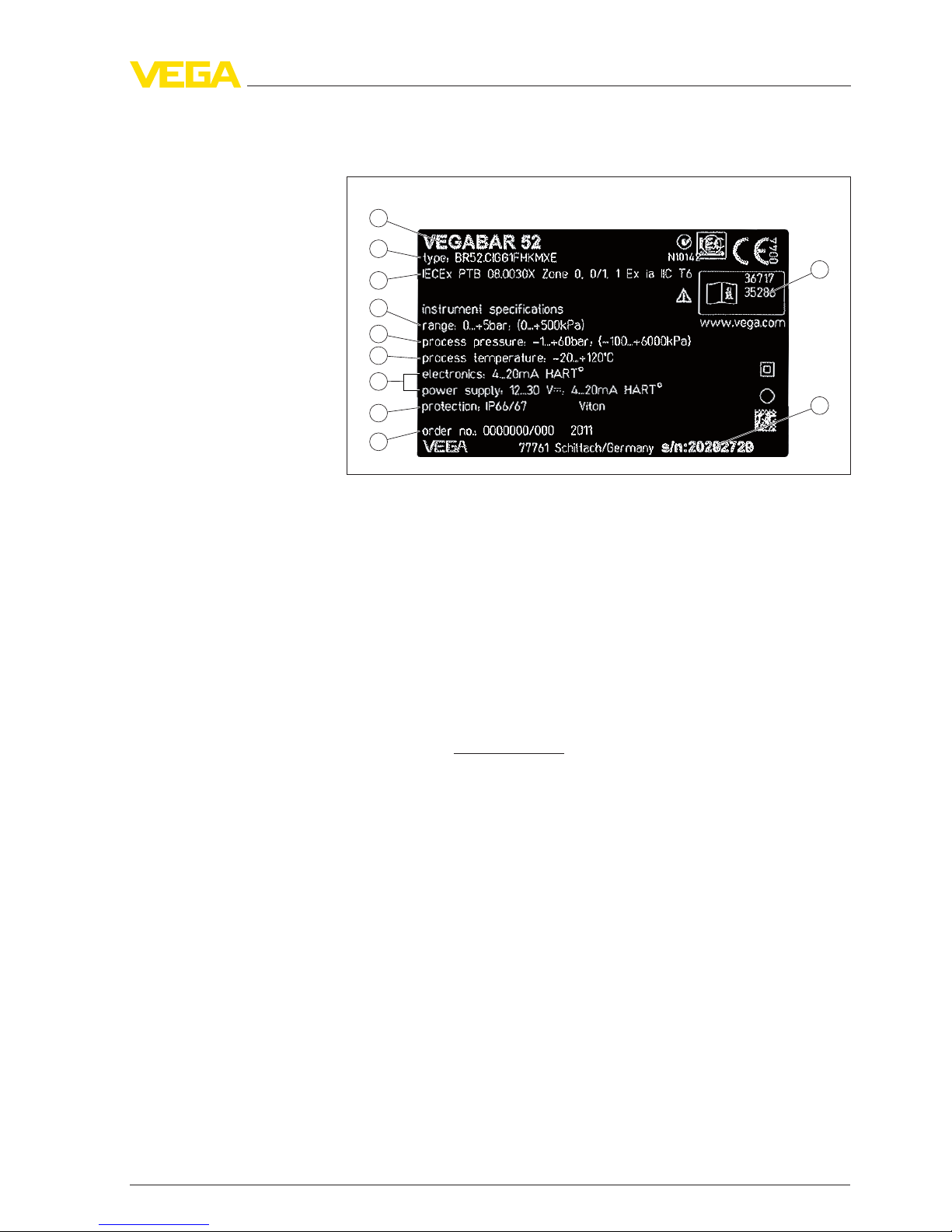
2.5Safety label on the instrument . . . . . . . . . . . . . . . . . . 6
2.6CE conformity ............................. 6
2.7Measuring range -permissible process pressure . . . . 6
2.8Fulfillment of NAMUR recommendations . . . . . . . . . . 6
2.9Safety instructions for Ex areas . . . . . . . . . . . . . . . . . 6
2.10 Environmental instructions..................... 6
3Product description
3.1Structure ................................. 7
3.2Principle of operation ........................ 9
3.3Operation................................. 10
3.4Packaging,transport and storage ............... 11
3.5Accessories and replacement parts . . . . . . . . . . . . . . 11
4Mounting
4.1General instructions ......................... 13
4.2Mounting preparations ....................... 14
4.3Mounting steps with straining clamp . . . . . . . . . . . . . 16
4.4Mounting steps with screwed connection . . . . . . . . . . 17
4.5Mounting steps with lock fitting . . . . . . . . . . . . . . . . . 18
4.6Mounting steps with housing and thread . . . . . . . . . . 19
4.7Mounting steps,external housing. . . . . . . . . . . . . . . . 20
5Connecting to power supply
5.1Preparing the connection ..................... 21
5.2Connection procedure........................ 22
5.3Wiring plan,single chamber housing . . . . . . . . . . . . . 24
5.4Wiring plan,double chamber housing . . . . . . . . . . . . 25
5.5Wiring plan,double chamber housing Ex d . . . . . . . . 27
5.6Wiring plan -version IP 66/IP 68,1bar . . . . . . . . . . . 29
5.7Wiring plan,external housing with version IP 68 . . . . . 29
5.8Switch-on phase............................ 32
6Set up with the indicating and adjustment module PLICSCOM
6.1Short description ........................... 33
6.2Insert indicating and adjustment module. . . . . . . . . . . 33
6.3Adjustment system .......................... 35
6.4Setup steps ............................... 36
2VEGABAR 66 •Foundation Fieldbus
Contents
36740-EN-120324