Veichi SI23-D1 series User manual

SI23 Solar Pump Inverter Manual
1
Chapter 1 Safety Requirement and Cautions
To ensure safety of your health, equipment and property, please read this chapter carefully before using the frequency inverter
and act in compliance with the instructions when installing,ebugging, running and overhauling the frequency inverter.
1.1 Safety Definition
Danger: it will cause danger of serious injuries and even death while operating against the rules.
Caution: it will cause danger of light injuries or equipment destruction while operating against the rules.
Note: some information is useful while operating and use frequency inverter.
1.2 Safety Requirements and Cautions
●Before Installation
Danger
1. Only qualified personnel can operate the equipment. Before operating, be sure to carefully read the manual about safety,
installation, operation and maintenance. The safe operation depends on the proper processes of choosing models,
carrying, installation, operation and maintenance.
Danger
1. Don’t use the damaged or incomplete frequency inverters; Otherwise, there is risk of injury.
●Installation
Danger
1. Please install the frequency inverter on metal or other nonflammable material, and keep it away from the combustible
material. Otherwise there is danger of fire;
2. No unauthorized modification to the frequency inverter; Otherwise there is danger of damaged.
3. Normal frequency inverter, which is not explosion-proof, can not be installed where with explosive gas or dust; Otherwise
there is danger of explosion.
Attention
1. When two frequency inverters are installed in the same control cabinet, pleas pay attention to the installing place to
guarantee the effective heat dissipation.
2. When carrying the frequency inverter, ease support its bottom.
●Wiring
Danger
1. Wire is connected only when the main circuit is cut off, otherwise there is a danger of shock.
2. Wire is connected by professional person only. Otherwise there is a danger of shock.
3. Earth must be reliable. Otherwise there is a danger of shock.
4. AC power supply should not be connected with output ports U, V, W, otherwise there is a danger of damage to frequency

SI23 Solar Pump Inverter Manual
2
inverter.
5. No drop of bolt, spacer, metal stick, conducting wire or other things into the inner of frequency inverter; Otherwise there is
a danger of fire or damage to frequency inverter.
Attention
1. If the damage to frequency inverter or other equipment is caused by improper wiring and utilization or unauthorized
alteration, the user should shoulder all responsibilities.
2. Please make sure all wirings meet EMC requirement and satisfy safety standard in the local area; Please refer to
recommendations in this manual or national standards of wire diameter to avoid accidents.
3. Static electricity on human body would seriously damage internal MOS transistor, etc. No touch the printed circuit boards,
IGBT or other internal devices without anti-static measure, otherwise it will cause the malfunction of frequency inverter.
4. Please don't connect phase shifter capacitance or LC/RC noise filter to the output circuit of frequency inverter; Otherwise it
will damage the frequency inverter.
5. Please don't connect the magnetic switch or magnetic contactor to the output circuit of frequency inverter; When frequency
inverter is in the operation with load, magnetic switch or magnetic contactor can make inverter over-current protection
function act. It will damage frequency inverter seriously.
6. Please don't disassemble the panel cover, it only needs to disassemble the terminal cover when wiring.
7. It is forbidden to do any pressure test on frequency inverter, otherwise it will damage the frequency inverter.
●Before Electrification
Danger
1. Please make sure that voltage grade of power supply is consistent with frequency inverter's voltage and then check
whether the wiring is correct and firm, and whether there is short circuit in peripheral equipment's circuit. Otherwise it will
damage frequency inverter and other equipment.
2. Before the frequency inverter is connected to the input power supply, make sure that the cover has been well fixed.
Otherwise it will cause electric shock.
3. For the frequency inverters whose storage time is over 1 year, when electrification, the voltage should be raised by booster
from low to high. Otherwise it will damage the frequency inverter.
Attention
1. Check if all periphery fittings are wired properly according to the handbook; Otherwise it will cause accidents.
●After Electrification
Danger
1. After electrified, it is forbidden to open the cover, make wiring, and check up; Otherwise, it will cause the danger of electric
shock.
2. After electrified, it is forbidden to contact internal wiring board and its parts. Otherwise it will cause the danger of electric
shock.
3. Do not operate or touch frequency inverter with wet hand. Otherwise there is danger of damage to frequency inverter and
electric shock.

SI23 Solar Pump Inverter Manual
3
Attention
1. Please set the parameter of frequency inverter cautiously; Otherwise it will damage equipment.
●Operation
Danger
1. Before running, please check and confirm the application range of the machine and equipment once more; Otherwise it
will cause accidents.
2. Please don't touch the cooling fan and braking resistance to check the temperature; Otherwise there is a danger of
getting burn.
3. Unprofessional workers are banned to check the signals in the running stage; Otherwise it will cause injuries and
damage the equipment.
Attention
1. Please don't turn off the equipment by switching off power; Please cut off the power supply after the electric machine
stops running; Otherwise it will damage the frequency inverter.
2. Please avoid anything dropping into the equipment when the frequency inverter is running; Otherwise it will cause
electric shock.
●Maintenance
Danger
1. Please don't maintain and repair the equipment with electric; Otherwise it will cause electric shock.
2. Before maintaining and repairing the frequency inverter, please make sure the indicator lights of power supply have
completely turned off; Otherwise it may cause electric shock and damage the frequency inverter.
3. Persons who have not passed specialized train are not allowed to conduct the frequency inverter maintenance;
Otherwise it may cause electric shock and damage the frequency inverter.
1.3 Cautions in Using
1. In application of this series frequency inverter, you have to confirm all machine insulation to prevent damage to the
equipment. Moreover, when the motor working in tough environment, please periodic inspect the electrical insulation to
ensure the safety of the system work.
2. If the motor adapter is not consistent with frequency inverter's rating current (The rating current of the motor is far smaller
than that of frequency inverter), please adjust the protective value to ensure safe running.
3. In occasions such as load raises, usually there is negative torque and frequency inverter breaks off for over-current or
over-voltage. In this case, you should consider choosing the matching brake unit.
4. Frequency inverter, in a certain output frequency range, can meet the mechanical resonance of the load equipment. To
avoid it, you can set up jumping frequency.
5. As output voltage of the inverter is pulse-wave type, if there is capacity which can improve power factor or
pressure-sensitive resistance which used for thunder-proof in the voltage output side, the frequency inverter will break off
or its parts will be damaged, so it is necessary to dismantle them. Moreover, it is proposed not install switch parts like air
switch and contactor (if it is necessary to install switch on output side, please make sure the output electricity of frequency

SI23 Solar Pump Inverter Manual
4
inverter is zero when the switch is working)
6. At over 1,000 meters altitude, the inverter’s heat dissipation function worsened due to the thin air, it is necessary to use
less.
7. The inverter output voltage is pulse wave type. If using digital multi-meter measurement, deviation of the reading will be
great. And the deviation is different by using different type of digital multi-meter. Under normal circumstances, while RMS
380V, digital multi-meter reading is around 450V.
8. Solar panel can be connected in the series or parallel. For rated voltage 380V controller, we suggest working voltage
between 480V and 560V while MPPT. What means the solar panel open circuit voltage should be between 600V and
700V.
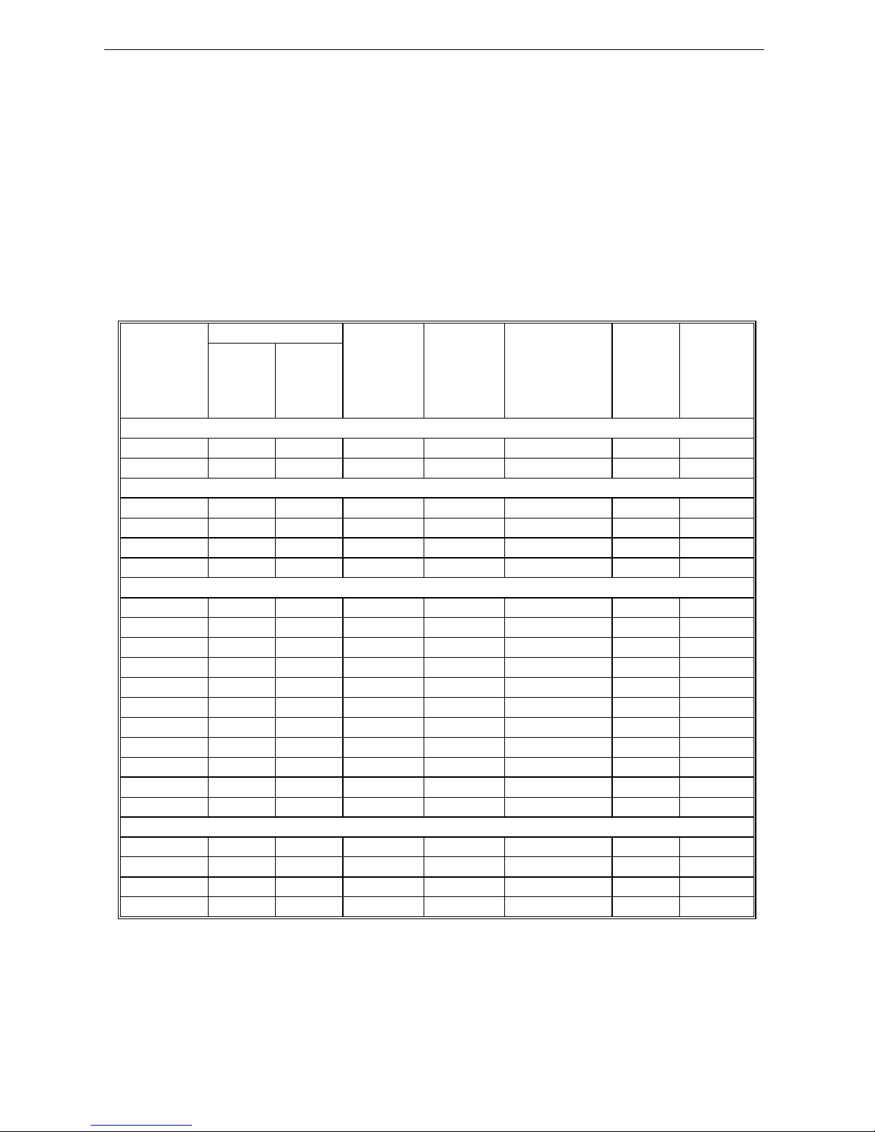
1.4 Technical Specification
Solar pump
inverter
power(KW)
Pump Max solar
power
input
(KW)
Max DC
input
voltage V
Recommend
Voc voltage (V)
Rated
output
current
(A)
Output
frequency
(Hz)
Rated
power
(KW)
Rated
voltage
(V)
SI23-D1 series, DC60-400VDC input, 3 phase 110-230VAC output
0.75 0.75 110 1.0 400 175~380 7A 0-600
1.5 1.5 110 1.95 400 175~380 10A 0-600
SI23-D3 series,DC150V-450V input, 3 phase 220-240VAC output
0.75 0.75 220 1.0 450 360~430 4A 0-600
1.5 1.5 220 1.95 450 360~430 7A 0-600
2.2 2.2 220 2.86 450 360~430 10A 0-600
4 4 220 5.4 450 360~430 16A 0-600
SI23-D5 series,DC250V to 780VDC input, 3 phase 380-460VAC output
0.75 0.75 380 1.0 780 620~750 3.0 0-600
1.5 1.5 380 2.2 780 620~750 4.0 0-600
2.2 2.2 380 3.3 780 620~750 6.0 0-600
4 4 380 5.6 780 620~750 10 0-600
5.5 5.5 380 8 780 620~750 13 0-600
7.5 7.5 380 10 780 620~750 17 0-600
11 11 380 14.3 780 620~750 25 0-600
15 15 380 19.5 780 620~750 32 0-600
18.5 18.5 380 23.4 780 620~750 38 0-600
22 22 380 28.6 780 620~750 45 0-600
30 30 380 39 780 620~750 60 0-600
SI23-T3 series,DC350V to 780VDC input,3phase 380-440VAC output
37 37 380 48.1 780 620~750 75 0-600
45 45 380 58.5 780 620~750 90 0-600
55 55 380 71.5 780 620~750 110 0-600
75 75 380 97.5 780 620~750 150 0-600
1.5 Cautions in Disposal
When you dispose frequency inverter, please pay attention to:
1. Electrolytic capacitor: the electrolytic capacitor of main circuit or the printing plate may explode when they are burned.
2. Plastic: plastic incineration may generate toxic gases.
3. Dispose method: please dispose as industrial waste.

SI23 Solar Pump Inverter Manual
5
Chapter 2 Installation and Wiring
2.1 Dimension of Inverter
Overall Dimension of Inverter (Plastic)
W
D
D1
H
W1
W2
A
B
H2
Installation Diameter
H1
MODEL Overall Dimension(mm) Installation Dimension(mm) Apertu
re
W H H1 D D1 W1
W2
H2 A B
SI23-D3-R75G
76 200
192 155
149
65 65 193 5.5 4 ф3-M4
SI23-D3-1R5G
SI23-D3-2R2G
100
242
231 155
149
84 86.
5 231.5
8 5.5 ф3-M4
SI23-D3-004G
SI23-D5-R75G
76 200
192 155
149
65 65 193 5.5 4 ф3-M4
SI23-D5-1R5G
SI23-D5-2R2G
SI23-D5-004G
100
242
231 155
149
84 86.
5 231.5
8 5.5 ф3-M4
SI23-D5-5R5G
SI23-D5-7R5G
116
320
307.5 175
169
98 100
307.5
9 6 ф3-M5
SI23-D5-011G

SI23 Solar Pump Inverter Manual
6
W
HH1
D
D1 W1
W2
B
H2
Installation Diameter
MODEL Overall Dimension(mm) Installation Dimension(mm) Aperture
W H H1 D D1 W1 W2 H2 B
SI23-D5-015G
142
383
372 225
219
125 100 372 6 ф4-M5 SI23-D5-018G
SI23-D5-022G
SI23-D5-030G
172
430
/ 255
219
150 150 416.5
7.5 ф4-M5
SI23-T3-037G

SI23 Solar Pump Inverter Manual
7
Overall Dimension of Inverter (Steel)
W
H
D
H1
W1
H2
Installation Diameter
MODEL Overall Dimension(mm) Installation Aperture
W H H1 D W1 H2
SI23-T3-045G
240 560 535 310 176 544 ф4-M6 SI23-T3-055G
SI23-T3-075G

SI23 Solar Pump Inverter Manual
8
2.2 Solar Pump Controller Wiring
●
Standard Connection Diagram
Note2
Note:Function description in brackets is
factory default
Analog monitoring
signal output
TA
TB
TC
+24V
Y
Shielded cable (the
end close to VFD
grounding)
_
mA
20
10
0
-
+
V
W
U
M
~
Shielded cable or armoured cable
(the end close to VFD grounding)
E(The grounding resistance
is less than 10 ohms)
W
V
U
Output Rector
P1
+
( )
+10V
Frequency control input
R
T
S
AC POWER INPUT
GND
AI1
AI2
Shielded cable (the end close to
VFD grounding)
Multi function contact input
(Water full detection reset)
(Water full detection alarm)
(Reverse)
(Forward)
(Free STOP)
COM
X3
X4
X5
X1
X2
PB
( )
+
(-)
VFD
S
T
R
-
+
GND
A0
Coil
COM
Passive contact
output
AC220V
AC0V
Coil
MAX Output Of Contact:
3A/240VAC
5A/30VDC
1.MAX Output of +24V Port:DC24V/100mA
Note:When output type of AO port as
frequency and Voltage,
Maximum Output:2mA
2.Inner resistance of AI1/AI2 Port
1.MAX Output of +10V port :50mANote:
2.Max Output of Y Port :DC24V/50mA
Note:
represent control circuit terminals.
represent main circuit terminals;
Legend: 1.Symbol
Shielded cable
(the end close
to VFD grounding)
Input Rector
ContactorMCCB +
( )
PUL
+24V
PLC
COM
Analog Voltage/Current quantity input
A+
B-
RS485 Differential
Communication
120Ω
Open collector(OC)
state output
Analog Voltage/Current quantity input
2.Symbol
DC POWER
INPUT
Note: When connect solar panel, both AC input (R, T) and DC input (+, -) is okay, AC input is prefer.
●
Auxiliary Terminal Output Capacity
Terminal Function Definition Max Output
+10V 10V auxiliary power supply output, constitutes loop with GND. 50mA
A0 Analog monitor output, constitutes loop with GND. Max output 2mA as frequency,
voltage signal
+24V 24V auxiliary power supply output, constitutes loop with COM. 100mA
Y Collector open circuit output; can set the action-object by program.
DC24V/50mA
TA/TB/TC Passive connector output; can set the action-object by program. 3A/240VAC
●
Function Specification of Switch Terminals
Switch Terminal Selecting Position Function Specification
RS485 Terminal Resistor RS485 Communication :connect with 120Ω terminal resistor
AO-F Output- frequency 0~100kHz frequency output
AO-I Output- Current 0~20mA current output or 4~20mA current output
AO-U Output- Voltage 0~10V voltage output
AI1 Input- Current/Voltage AI1: Input 0~20mA or 0~10V
AI2 Input- Current/Voltage AI2: Input 0~20mA or 0~10V

SI23 Solar Pump Inverter Manual
9
Chapter 3 Keyboard layout and functions specification
●
Keyboard Appearance
●
Key function
Key
Name
Function
Menu key
Enter menu while standby or running. Presses this key to return while modify
parameter. While standby or running, press for 1 sec to enter condition monitoring
interface.
Confirm/Shift
key
Press to modify parameter while in menu interface. Press again to confirm after
modifying; Press this key for 1 Sec to shift digit, and long press to cycle. Each digit
flashes three time to shift to next digit.
Up/down key
Select parameter group in menu interface. Modify parameter in modify state. Modify
given frequency, ID given while at standby or monitoring state (While given frequency,
PID are set by keyboard and [F4.09] needs to be set.
Run key
While run/stop is controlled by keyboard, press this key, inverter forward runs, and the
indicator is always on. While reverse, the indicator sparks.
Stop/reset key
Machine stops if press it while run/stop is controlled by keyboard. Its efficiency range is
defined by [F4.08]. Inverter resets if press it in fault state (no reset if fault is not
solved).

SI23 Solar Pump Inverter Manual
10
Chapter 4 Fault Diagnosis and Solution
This chapter describes the inverter fault, alerts, and operation of the failure on the inverter, the display information on inverter
and countermeasures.
Fault Information and Description in Detail
Keypad
display
Fault
code Fault type Possibility reason Troubleshooting
E.LU2 Under voltage at
runs
●Power voltage too low
●DC main contactor don’t
close
●Check input power to solve
● Ask support
E.oU1 Over voltage at
acceleration
●Power voltage fluctuation
over limit
●Too start rotating motor
● Check power grid
● Restart until motor is stop
completely, or set [F1.00] set for 1
or 2
E.oU2 Over voltage
during deceleration
●Deceleration time too small
●The driving load too heavy
●Power voltage fluctuation
over limit
●Prolong deceleration time
●Reduce the load, or select bigger
capacitor drive, or connect braking
unit
● Check input power
E.oU3 Overvoltage at
constant speed
●The input voltage is too
high.
●An external force drives the
motor during deceleration
●Adjust the voltage to
normal range.
●Cancel the external force or install
the braking resistor.
E.oU4 Over voltage at
stop ●Voltage fluctuate above limit
● Check the input voltage
E.oC1
Over current
during
acceleration
●Acceleration time is too
short
●To start rotating motor
●V/F setting not correct or
torque boost setting too big
●Solar drive capacitor is too
small
●Prolong acceleration time
●Restart motor when it on still, or set
F1.00 for 1 or 2.
● Reset V/f curve or torque boost
setting
E.oC2 Over current
during deceleration
●The output circuit is
grounded or short circuited.
●Motor auto-tuning is not
performed.
●The acceleration time is too
short.
●Manual torque boost or V/F
● Eliminate external faults.
●Perform the motor auto tuning.
● Increase the acceleration time.
● Adjust the manual torque boost or
V/F curve.
● Adjust the voltage to
normal range.

SI23 Solar Pump Inverter Manual
11
curve is not appropriate.
● The voltage is too low.
●The startup operation is
performed on the rotating
motor.
●A sudden load is added
during acceleration.
●The AC drive model is of
too small power class.
● Select rotational speed tracking
restart or start the motor after it
stops.
● Remove the added load.
● Select an AC drive of higher power
class.
E.oC3 Over current at
constant speed
●The output circuit is
grounded or short circuited.
●Motor auto-tuning is not
performed.
●The voltage is too low.
● A sudden load is added
during operation.
●The AC drive model is of
too small power class
● Eliminate external faults.
●Perform the motor auto tuning.
●Adjust the voltage to normal range.
● Remove the added load.
● Select an AC drive of higher power
class.
E.oL1 Motor overload
● Boost torque is too big
under VF control
●ACC. and DEC. time is too
short
●Motor parameters setting is
improperly
●Restart motor which in
counter rotate
●The grid voltage is too lower
●Load is too big or motor
block load
●AC drive selected is too
load
●Reduce boost torque
●Increase the ACC./DEC. time
● Reset motor parameters
●Reduce current limit and adopt
speed tracking
● Check grid voltage
● Check load condition
●Change bigger power AC drive
E.oL2 AC drive overload
●Boost torque is too big
under VF control
●ACC. and DEC. time is too
short
●Motor parameters setting is
improperly
●Restart motor which in
counter rotate
●The grid voltage is too lower
●Load is too big or motor
block load
●Reduce boost torque
● increase the ACC./DEC. time
●reset motor parameters
●Reduce current limit and adopt
speed tracking
● Too check grid voltage
●Too check load
●change bigger power AC drive

SI23 Solar Pump Inverter Manual
12
●AC drive selected is too
load
E. SC System abnormal
●Deceleration is too short
●Short circuit of solar drive
output or phase output short
circuit to ground
● Module damage
● EMC interface
● Prolong acceleration time
● To check peripheral equipment
● Ask to support
● Check the wiring layout, cable
ground
E.oH1 Inverter over-heat
●Temperature is too high.
● Air channel is blocked.
● Fan connection parts is
loose.
● Fan is damaged.
●Temperature detection
circuit fault
● Make the environment meet the
requirement.
● Clear the air channel.
● Check and reconnect the wire
● Change the same new fan.
● Seek support from factory.
E.oH2 Rectifier over-heat
●Temperature is too high.
● Air channel is blocked.
● Fan connection parts is
loose.
● Fan is damaged.
● Temperature detection
circuit fault
●Make the environment meeting the
requirement.
● Clear the air channel.
● Check and reconnect the wire.
● Change the same new fan.
● Seek support from factory.
E.TE1 Motor static
detection fault
● Detection overtime
●Start static detection while
motor is running.
● Capacitance difference is
too big between motor and
inverter.
●Motor parameter setting
mistake.
● Check motor connection wire.
● Detect after motor stopping totally.
● Change inverter model.
● Reset parameter according to
nameplate.
E.TE2 Motor rotation
detection fault
●Detect while motor is
running.
● Detect with load.
● Detection overtime
●Capacitance difference is
too big between motor and
inverter.
●Motor parameter setting
mistake.
● Detect after motor stop totally.
● Re-detect without load.
● Check motor connection wire.
● Change inverter model.
● Reset parameter according to
nameplate.

SI23 Solar Pump Inverter Manual
13
E.EEP Memory fault
●Electromagnetic disturb in
memory period.
● EEPROM damage.
● Resume load and save.
● Seek support from factory.
LIFE Reserved
E.ILF Input phase loss ●3-phase input power open
phase.
●Check 3-phase power supply and
the phase.
●Check 3-phase power supply
wiring.
E.oLF Output phase loss
●3-phase output power open
phase
● Check 3-phase output voltage and
current.
● Check wiring.
E.Gnd
Output earth
terminal short
circuit.
●Check wiring and insulation.
●Output earth
E.HAL Current detection
fault
● Detect circuit fault.
● Phase imbalance
●Seek support from factory
● Check motor and wiring.
E.PAn Keyboard connect
fault
● Keyboard wire fault.
●Keyboard component
damage.
● Check keyboard wire.
●Seek support from factory.
Rs485c
ommuni
cation
fault
● Unsuitable baud
rate setting.
●Communication
wire breaks.
●Communication
format does not
match upper
machine.
●Set suitable baud rate
setting.
●Check communication wire.
●Make sure right
communication format.
●RS485communication fault
E.CPE Parameter copy
fault
●Parameter copy
communication is fault.
●Copy keyboard does not
match the inverter.
● Check wire.
●Select the specified external
keyboard model.

SI23 Solar Pump Inverter Manual
14
Chapter 5 Parameters List
This chapter just provides function parameter table. Specifications refer to AC300 technical manual or inquiry the company.
“●”: Parameter can be changed in the running state.
“〇”: Parameter can’t be changed in the running state.
“×”: Parameter can be read only.
“–”: Factory setting parameter, only factory can set.
“※”: Parameter is related to the model.
Basic parameters
NO. Function
description Range of settings and definition
Factory default
Feature
Address
F00.00 Motor control
mode
Asynchronous motor control mode:
0: V/F control
Synchronous motor control mode:
6: High-performance VC without PG
0 〇 0x000
F00.01 Reserved
F00.02
Run
command
channel
0: Keyboard
control
1: Terminal
control
2: RS485 communication control
3: Reserved 0 ● 0x002
F00.03
Frequency
given source
channel A
0: Keyboard number given
1: Reserved
2: Voltage/Current analog AI1 given
3: Voltage/Current analog AI2 given
4: Reserved
5: Terminal pulse PUL given
6: RS485 communication given
7: Terminal UP/DW control
8: PID control given
9: Program control (PLC) given
10: Optional card
11: Multi-steps speed given
0 ● 0x003
F00.04
Frequency
given source
channel B
1 ● 0x004
F00.05
Frequency
channel B
reference
source
0: Max. output frequency as reference source
1: Set frequency of channel A as reference source 0 ● 0x005
F00.06
Frequency
given source
selection
0: Channel A
1: Channel B
2: Channel A+Channel B
3: Channel A-Channel B
4: Max. value of Channel A and Channel B
5: Min. value of Channel A and Channel B
0 ● 0x006
F00.07 Running
Command
LED“0”digit: keyboard command instruction binding
LED“00”digit: terminal command instruction binding 0000 ● 0x007

SI23 Solar Pump Inverter Manual
15
Binding LED“000”digit: communication command instruction
binding
LED“0000”digit: optional card command instruction
binding
0 : no binding
1 : keyboard number given frequency
2 : Reserved
3 : Voltage/Current analog AI1 given
4 : Voltage/Current analog AI2 given
5 : Reserved
6 : Terminal pulse PUL given
7: RS485 communication given
8 : Terminal UP/DW control
9 : PID control given
A: Program control (PLC) given
B: Optional card
C: Multi-steps speed given
F00.08
Keyboard
digital setting
frequency
0~upper limit 50.00Hz
● 0x008
F00.09 Max
frequency upper limit~600.00Hz 50.00Hz
〇 0x009
F00.10
Upper limit
frequency
source
selection
0: Upper limit frequency digital given
1: Reserved
2: Voltage/Current analog AI1 give
3: Voltage/Current analog AI2 given
4: Reserved
5: Terminal pulse PUL given
6: RS485 communication given
7: Optional card
0 ● 0x00A
F00.11
Upper
frequency
limit digital
setting
Lower limit frequency~max frequency 50.00Hz
● 0x00B
F00.12 Lower limit
frequency 0.00~upper limit frequency 0.00Hz ● 0x00C
F00.13
Lower limit
frequency
running mode
0: Stop output, enter into pause running state
1: Run at lower limit frequency 1 〇 0x00D
F00.14 ACC time 1 0.01~650.00s 20.00s ※ 0x00E
F00.15 DEC time 1 0.01~650.00s 20.00s ※ 0x00F
F00.16
Rotary
direction
selection
LED“0”digit: running direction takes the opposite
0: Direction unchanged
1: Direction takes the opposite
LED“00”digit: running direction prohibited
0:Forward and reverse commands are allowed
1: Only FWD command allowed
2: Only REV command allowed
LED“000”digit: frequency control direction selection
0000 〇 0x010

SI23 Solar Pump Inverter Manual
16
0: Invalid 1: Valid
LED“0000”digit: reserved
F00.17 G/P Model
Setting 0:G Type 1:P Type 0 ● 0x011
F00.18 Reserved
F00.19 Parameter
initialization
0: No action
1: Restore factory default (not restoring motor parameters)
2: Restore factory default (restoring motor parameters)
3: Clear malfunction records
0 〇 0x013
Operation Control Parameters Group
NO. Function description Range of settings and definition
Factory setting
Feature
Address
F01.10 Stop mode 0:DEC stop 1:Free stop 0 ● 0x10A
F01.16 ACC/DEC selection
LED “0” digit: time base selection
0: max frequency
1: fixed frequency 50Hz
2: set frequency
LED“00”digit: S ACC/DEC selection
0: Beeline ACC/DEC
1: S Curve ACC/DEC
LED “000” digit: reserved
LED “0000” digit: reserved
0000 〇 0x110
F01.35 Power off restart action
selection 0:Invalid 1:Valid 0 〇 0x123
F01.36 Power off restart
waiting time 0.00~60.00s 0.50s 〇 0x124
Switching value terminal parameters
NO. Function description Range of setting and definition
Factory setting
Feature
Address
F02.00 Input terminal 1(X1) 0: No function
1:Forward
2:Reverse
80: Water fulfilled detect alarm
81:Water fulfilled detect reset
1 〇 0x200
F02.01 Input terminal 2(X2) 2 〇 0x201
F02.02 Input terminal 3(X3) 80 〇 0x202
F02.03 Input terminal 4(X4) 81 〇 0x203
F02.24 Terminal operate
protection
0: OFF 1:ON
LED “0” digit: Terminal operate protection
when abnormal exit
LED “00” digit: Jog terminal operate
0111 〇 0x218

SI23 Solar Pump Inverter Manual
17
protection when abnormal exit
LED “000” digit: Operate protection when
command channel switch to terminal
F02.42 Output terminal polarity
selection
0: Positive 1: Negative
LED “0” digit: Terminal Y
LED “00” digit: Relay output 1
LED “000” digit: Extended Y1 terminal
LED “0000” digit: Extended Relay output 2
0000 ● 0x22A
F02.60 Virtual vX1 terminal
function selection
0: No function
1:Forward
2:Reverse
10: Water fulfilled detect alarm
11:Water fulfilled detect reset
0 ● 0x238
F02.61 Virtual vX2 terminal
function selection 0 ● 0x239
F02.62 Virtual vX3 terminal
function selection 0 ● 0x23A
F02.63 Virtual vX4 terminal
function selection 0 ● 0x23B
F02.64 vX terminal valid state
source
0: internal connection with virtual vYn
1: Connect with physical terminal Xn
2: function code setting valid or not
LED “0” digit: virtual vX1
LED “00” digit: virtual vX2
LED “000” digit: virtual vX3
LED “0000” digit: virtual vX4
0 ● 0x23C
F02.65
Virtual vX terminal
function code setting
valid state
0: invalid 1: valid
LED “0” digit: virtual vX1
LED “00” digit: virtual vX2
LED “000” digit: virtual vX3
LED “0000” digit: virtual vX4
0 ● 0x23D
System parameters
NO. Function description Range of settings and definition
Factory setting
Feature
Address
F04.00 Parameter and key
lock selections
0: Not locked
1: Function parameter locked
2: Function parameter and key locked (except for
RUN/STOP/JOG)
3: All function parameter and key locked
0 ●
0x400
F04.01 User password 0~65535 0 ●
0x401
F04.05 Parameter copy
0: No function
1: Send inverter parameters to keyboard and save
2: Send keyboard parameters to inverter
Remaining value: no operation
0 〇
0x405

SI23 Solar Pump Inverter Manual
18
F04.08 STOP key setting
0: Non-keyboard control mode is invalid
1: Non-keyboard control mode stops according to
stop mode
2: Non-keyboard control mode stop according to free
stop mode
1 〇
0x408
F04.09 UP/DOWN key
selection
LED “0” digit: keyboard UN/DOWN key modify
selection
0: Invalid
1: Modify frequency setting by key board numbers
F00.08
2: Modify PID give setting by key board numbers
F11.01
LED “00” digit: power off storage selection
0: No save frequency after power off
1: Save frequency after power off
LED “000” digit: action limit
0: Operation stop for adjusting
1: Adjusting only in operation, stop for holding
2: Adjusting in operation, stop for clearing
0011 〇
0x409
F04.14
The display content of
the first line in running
state
LED "0" and “00” digit: display the first group
00~63
LED "000" and "0000" digit: display the second
group
00~63
1101 ●
0x40E
F04.15
The display content of
the first line in running
state
Same as above 0402 ●
0x40F
F04.16
The display content of
the first line in stop
state
Same as above 1100 ●
0x410
F04.17
The display content of
the first line in stop
state
Same as above 0402 ●
0x411
F04.18
The display content of
the second line in
running state
Same as above 0402 ●
0x412
F04.19
The display content of
the second line in
running state
Same as above 1210 ●
0x413
F04.20
The display content of
the second line in
stop state
Same as above 0402 ●
0x414
F04.21
The display content of
the second line in
stop state
Same as above 1210 ●
0x415

SI23 Solar Pump Inverter Manual
19
F04.22 Keyboard display item
setting
LED “0” digit: output frequency selection
0: Aim frequency
1: Running frequency
LED “000” digit: power display dimension
0: Power display percentage (%)
1: Power display kilowatt (KW)
0000 ●
0x416
F04.23 Monitor display
selection
LED “0” digit: C00.00-C00.39
0: Normal 1: Debugging
LED “00” digit: C00.40-C00.69
0: No display 1: Normal display
0000 ●
0x417
F04.24 Rotate speed display
coefficient 0.0~500.0% 0000 ●
0x418
F04.25 Power display
coefficient 0.0~500.0% 100.0% ●
0x419
F04.28 Fan control
0:After power on the fan runs
1: Stop associated with temperature, running is rotary
2: Running associated with temperature, stop while
the fan stops
1 ●
0x41C
F04.32 PWM carrier
frequency 0.7~16.0kHz Model
set ※
0x420
F04.33 PWM control mode
LED “0” digit: carrier associated with
temperature
0: Temperature independent
1: Temperature dependent
LED “00” digit : carrier associated with output
frequency
0:not associated 1: associated
LED “000” digit: random PWM valid
0: Prohibited 1: Valid
LED “0000” digit: PWM modulation mode
0: Only use three-phase modulation
1: Two-phase and three-phase modulation
automatically switched
1111 ●
0x421
Motor Parameters
NO. Function description Range of settings and definition
Factory default
Feature
Address
F05.00 Motor mode
0: Asynchronous motors (AM)
1: Permanent magnet synchronous motors
(PM)
0 × 0x500
F05.01 Number of motor poles 2~98 4 〇 0x501

SI23 Solar Pump Inverter Manual
20
F05.02 Motor rated power 0.1~1000.0kW Model
set ※ 0x502
F05.03 Motor rated frequency 0.01~max frequency Model
set ※ 0x503
F05.04 Motor rated speed 1~65000rpm Model ※ 0x504
F05.05 Motor rated voltage 1~1500V Model ※ 0x505
F05.06 Motor rated current 0.1~3000.0A Model ※ 0x506
F05.07 Asynchronous motor
no-load current 0.1~3000.0A Model
set ※ 0x507
F05.08 Asynchronous motor
stator resistance 0.01~50.00% Model
set ※ 0x508
F05.09 Asynchronous motor rotor
resistance 0.01~50.00% Model
set ※ 0x509
F05.10 Asynchronous motor
stator leakage inductance
0.01~50.00% Model
set ※ 0x50A
F05.11 Asynchronous motor
stator inductance 0.1~2000.0% Model
set ※ 0x50B
F05.12 synchronous motor stator
resistance 0.01~50.00% Model
set ※ 0x50C
F05.13 Synchronous machine d
axis inductance 0.01~200.00% Model
set ※ 0x50D
F05.14 Synchronous machine q
axis inductance 0.01~200.00% Model
set ※ 0x50E
F05.15 Synchronous machine
back EMF 1~1500V Model
set ※ 0x50F
F05.16 Synchronous machine
encoder installation angle
0.0°~360.0° Model
set ※ 0x510
F05.20 Motor parameters
self-adjustment selections
0: No operation
1: Rotary type self-tuning
2: Static type self-tuning
3: Stator resistance self-tuning
0 〇 0x514
F05.21 Synchronous machine
poles searching function
LED “0” digit: closed-loop vector
0: OFF
1: ON
2: On, only operate firstly when electrify
LED “00” digit: open-loop vector
0: OFF
1: ON
2: ON, only operate firstly when electrify
0010 〇 0x515
Motor VC Parameters
NO. Function description Range of settings
and definition
Factory
default Feature
Address
This manual suits for next models
22
Table of contents
Other Veichi Inverter manuals

Veichi
Veichi SI23 series User manual

Veichi
Veichi AC70T series User manual

Veichi
Veichi AC100-T3-1R5G User manual

Veichi
Veichi SI30 series User manual

Veichi
Veichi AC70T series User manual

Veichi
Veichi AC200 Series User manual

Veichi
Veichi AC10 Series User manual

Veichi
Veichi SI30 series User manual

Veichi
Veichi AC70 series User manual

Veichi
Veichi SI22 series User manual
Popular Inverter manuals by other brands

INVT
INVT Goodrive 800 Series Operation manual

SOLIS
SOLIS Mini-700-4G Installation and operation manual

Riello
Riello AARIA ONE INVERTER 25 Installation and technical service instructions

PrimeVOLT
PrimeVOLT PV 5KTL-D3/G2 user manual

Omron
Omron 3G3RX-V1 Series Connection guide

THOR
THOR TH225 instruction manual