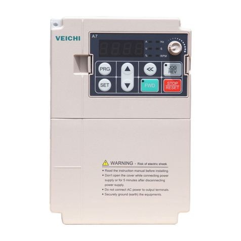
Veichi AC70T series User manual

AC70T Crane Purpose Inverter
Manual

Preface
First of all, thank you for using AC70T series crane special inverter.
VEICHI Electric is committed to creating safe, efficient and highly reliable lifting products.
Combined with years of experience in the lifting industry, the AC70T series of special machines
for lifting industry are launched with excellent control performance and functions, integrating
brake control, smooth lifting, constant power, zero-speed hovering, variable amplitude anti-
shaking, brake torque detection and other special functions, which are applied to drive lifting,
slewing and translating mechanisms of lifting equipment.
This manual introduces how to properly use the AC70T series inverter for lifting, providing
users with notes on how to install, parameter setting, operation and troubleshooting, etc.
In order to use this product correctly, be sure to read the manual carefully before use, if you
have doubts about the contents of this manual, please consult our technical staff to provide you
with assistance, which will help you use this series of products safely and correctly.
Our company is always committed to product innovation and technological breakthroughs to
provide the best products and solutions to meet the field applications in various fields of
lifting.The content is subject to change without prior notice due to continuous product updates
and upgrades.

Version change records
Date
Change content
Changed
version
2022.01
1、New debugging guide
2、New FE group lifting special function code 1
3、Modify FF group lifting special function code 2
4、Modify special function
V1.5

I
CATALOGUE
1 OVERVIEW ...................................................................................................................1
1.1 SAFETY PRECAUTIONS ................................................................................... 1
1.2 TECHNICAL SPECIFICATIONS........................................................................... 5
1.3 PRODUCT FEATURE ........................................................................................ 7
2 BEFORE USING ............................................................................................................8
2.1 PRODUCT ARRIVAL INSPECTION ...................................................................... 8
2.2 NAMEPLATE ................................................................................................... 8
2.3 TECHNICAL SPECIFICATIONS........................................................................... 8
2.4 PRODUCT SIZE ............................................................................................. 10
2.5 ELECTRICAL INSTALLATION .......................................................................... 13
2.6 STANDARD CONNECTION DIAGRAM .............................................................. 14
2.7 MAIN CIRCUIT TERMINAL ............................................................................. 18
2.8 CONTROL CIRCUIT TERMINAL ....................................................................... 20
3 BASIC OPERATION ...................................................................................................24
3.1 SAFETY PRECAUTIONS ................................................................................. 24
3.2 KEYBOARD LAYOUT AND FUNCTION DESCRIPTION......................................... 25
3.3 KEYBOARD INDICATOR MEANING ................................................................. 26
3.4 DIGITAL TEXT CROSS-REFERENCE TABLE....................................................... 27
3.5 BASIC OPERATION ........................................................................................ 28
4 DEBUGGING GUIDANCE..........................................................................................31
4.1 PANEL UNLOCKING ...................................................................................... 31
4.2 COMMISSIONING GUIDE ............................................................................... 32
4.3 CONFIRMATION BEFORE TURNING ON THE POWER ......................................... 33
4.4 CONFIRMATION AFTER TURNING ON THE POWER............................................ 33
4.5 SELF-LEARNING OF MOTOR PARAMETERS...................................................... 33
4.5.1 Self-study methods and instructions ..................................................... 33
4.5.2 Self-study steps..................................................................................... 34
4.6 MOTOR CONTROL METHOD........................................................................... 34

AC70T 起重专用变频器使用说明书 目录
II
4.7 START AND SHUTDOWN COMMANDS ............................................................. 35
4.8 MULTI-SPEED SETTING ................................................................................ 36
4.9 ANALOG INPUT PORT .................................................................................... 37
4.10 ANALOG OUTPUT PORT ............................................................................... 37
5. DEDICATED FUNCTION DESCRIPTION ...............................................................39
5.1 BRAKE CONTROL ......................................................................................... 39
5.2 BRAKE FAILURE PROTECTION ....................................................................... 41
5.2.1 Function Description............................................................................. 41
5.2.2 Cautions ............................................................................................... 41
5.2.3 Related parameters.............................................................................. 41
5.3 BRAKE TORQUE DETECTION.......................................................................... 42
5.3.1 Activation method................................................................................ 42
5.3.2 Working Process................................................................................... 42
5.3.3 Related parameters.............................................................................. 42
5.4 CONSTANT POWER CONTROL ........................................................................ 43
5.5 SMOOTH LIFT ............................................................................................... 43
5.5.1 Function Description............................................................................. 44
5.5.2 Related parameters.............................................................................. 44
5.6 LIFTING AND ANTI-HANGING ........................................................................ 45
5.6.1 Working Process................................................................................... 45
5.6.2 Related parameters.............................................................................. 45
5.7 VARIABLE ANTI-SWAY .................................................................................. 46
5.7.1 Function Description............................................................................. 46
5.7.2 Operation guidance.............................................................................. 46
5.7.3 Related parameters.............................................................................. 47
5.8 ANT SPEED .................................................................................................. 48
5.9 SLEWING CONTROL ...................................................................................... 48
Note: Some rotary mechanisms are equipped with common motors with eddy
current brakes, the eddy current-free control solution is still recommended and
the eddy current coil on the motor side can be left unwired........................... 49
5.9.1 Eddy current free control ...................................................................... 49
5.9.2 With eddy current control..................................................................... 50
5.10 EDDY CURRENT CONTROL .......................................................................... 51
目录 AC70T 起重专用变频器使用说明书
III
5.101 Determination of the eddy current control method.............................. 51
5.10.2 Eddy current module polarity determination ...................................... 52
Mode 1: F3.53 hundred or thousand digits set to 1........................................ 52
Mode 2 or Mode 3: FF.53 set to 0. ................................................................. 52
5.10.3 Adjusting eddy current control............................................................ 52
5.11 SLEWING FLEXIBILITY CONTROL................................................................. 53
5.12 ROTATION-SPECIFIC ACCELERATION AND DECELERATION............................. 55
6. FUNCTION PARAMETER TABLE ......................................................................................58
6.1 F0 BASIC PARAMETERS GROUP............................................................................ 58
6.2 F1 RUN CONTROL PARAMETERS........................................................................... 60
6.3 F2 DIGITAL TERMINAL PARAMETER GROUP ........................................................... 64
6.4 F3 ANALOG TERMINAL PARAMETER GROUP .......................................................... 71
6.5 F4 SYSTEM PARAMETER GROUP ......................................................................... 79
6.6 F5 MOTOR PARAMETER GROUP ......................................................................... 87
6.7 F6 MOTOR VC PARAMETER GROUP .................................................................... 90
6.8 F8 MOTOR V/F CONTROL PARAMETER ......................................................... 96
6.9 FA PROTECTION AND FAULT PARAMETER GROUPS ........................................102
6.10 FB STEP ACCELERATION AND DECELERATION .............................................114
6.11 FC MULTI-SPEED PARAMETER SETTING ..............................................................115
6.12 FD COMMUNICATION CONTROL FUNCTION PARAMETER GROUP...................117
6.13 FE LIFTING-SPECIFIC FUNCTION GROUPS 1.................................................122
6.14 FF LIFTING-SPECIFIC FUNCTION GROUPS 2...............................................129
7 TERMINAL FUNCTION SELECTION ....................................................................140
8 MONITORING CODE...............................................................................................142
9 FAULT INFORMATION............................................................................................145
5.1 FAULT TYPES ..............................................................................................145
9.2 FAULT INFORMATION AND DETAILS......................................................................145
9.3 FAULT WARNING .........................................................................................150
10 RECOMMENDED SELECTION OF ACCESSORIES ...........................................151
10.1 BRAKING RESISTOR SELECTION .................................................................151
10.2 PG CARD SELECTION ................................................................................153

1
1 Overview
Thank you for using the AC70T high performance crane inverter designed and
manufactured by VEICHI Electric Co. This manual describes how to use this product properly
to get good benefits. Please be sure to read this manual carefully before using the product
(installation, wiring, operation, maintenance, inspection, etc.).
1.1 Safety Precautions
To ensure safe, reliable and reasonable use of this product, please use the product only
after fully understanding the safety precautions described in this manual.
Warning signs and meaning
The following marks are used in this manual to indicate that the place is important
regarding safety. Failure to observe these precautions may result in personal injury or death,
damage to this product and associated systems.
Danger
Danger:If operated incorrectly, it may result in death or a major safety accident.
Warning
Warning:If operated incorrectly, it may result in death or a major safety accident.
Caution
Caution:If done incorrectly, minor injuries may result.
Important
Important:If operated incorrectly, this product and the associated system may be
damaged.
Operating Requirements
This product must be installed, wired, operated, and maintained by trained professionals.
By "trained professionals" in this manual, we mean that the personnel working on this
equipment must be trained in the installation, wiring, operation, and maintenance of the
equipment, and must be able to respond properly to emergencies that occur during use.
Security Guidance
The safety rules and warning signs are presented for your safety and are measures to
prevent personal injury to the operator and damage to this product and associated systems.
Please read this manual carefully before use and strictly follow the safety rules and warning

2
signs in this manual. The safety rules and warning signs are divided into the following
categories: general instructions, instructions for transportation and storage, instructions for
installation and wiring, instructions for operation, instructions for maintenance, and instructions
for disassembly and scrap disposal.
● General guidance
Warning
● This product carries a hazardous voltage and it controls a potentially hazardous
motion mechanism. Failure to comply with the regulations or to follow the
requirements of this manual may result in personal injury or death, damage to this
product and associated systems.
● Only trained professionals are allowed to operate this product, and before using this
product, be familiar with all the safety instructions and regulations for operation in
this manual; proper operation and maintenance is a reliable guarantee to achieve
safe and stable operation of this product.
● Do not perform wiring work when the power is on, otherwise there is a risk of death
by electric shock; when wiring, inspection, maintenance, etc., please cut off the
power of all associated equipment and make sure that the DC voltage of the main
circuit has dropped to a safe level, and wait 5 minutes before performing related
work.
Caution
● Prevent children and the public from coming into contact with or near this product.
● This product can only be used in accordance with the manufacturer's specified
purpose and may not be used in special areas related to emergency, rescue, marine,
medical, aviation, nuclear facilities, etc. without permission.
● Unauthorized modifications, use of spare parts not sold or recommended by the
manufacturer of this product may result in malfunction.
Important
● Be sure to deliver this manual to the actual user to ensure that the actual user reads
it carefully before using it.
● Please make sure you read and fully understand these safety rules and warning signs
before installing and commissioning the inverter.
● Guidance for transportation and storage
Warning
● Proper transportation, storage, installation, and careful operation and maintenance
are essential to the safe operation of the inverter.
Caution
● During transportation and storage to ensure that the inverter is not subject to shock
and vibration, must also ensure storage in a dry, non-corrosive gas, no conductive
dust and the ambient temperature is less than 60 ℃.

3
● Guidance on installation wiring
Warning
● Only trained professionals should operate this product.
● The power line, motor line and control line must be tightly connected, and the
grounding terminal must be reliably grounded, and the grounding resistance is less
than 10Ω.
● Before opening the inverter panel, disconnect the power to all associated equipment
and make sure the main circuit DC voltage has dropped to a safe level, and wait 5
minutes before performing related operations.
● Human static electricity can seriously damage the internal sensitive devices. Before
carrying out related operations, please observe the measures and methods specified
in the electrostatic preventive measures (ESD), otherwise the inverter may be
damaged.
● Since the inverter output voltage is pulse waveform, if there are capacitors or
varistors for lightning protection installed on the output side to improve the power
factor, be sure to remove or modify them on the input side of the inverter.
● Do not add switching devices such as circuit breakers and contactors on the output
side of the inverter (if you must connect a switching device on the output side, you
must ensure that the output current of the inverter is zero when the switch is operated
in the control).
● Guidance for running
Warning
● Inverters operate at high voltages, and dangerous voltages are inevitably present on
some parts of this product.
● Regardless of where the fault occurs in the control equipment, it may cause a major
accident or even personal injury, i.e., there is a potentially dangerous fault; therefore,
additional external precautions or other devices to ensure safe operation must be
taken, e.g., installation of independent current-limiting switches, mechanical
guards, etc.
● In order to ensure that the motor overload protection can operate correctly, the motor
parameters input to the inverter must match exactly with the actual motor used.
● Guidance on maintenance
Warning
● Maintenance of this product should only be performed by the service department of
VEICHI Electric Limited, by an authorized VEICHI Electric Limited repair center,
or by professionals trained and authorized by VEICHI Electric Limited, who are
fully familiar with the safety warnings and operating instructions presented in this
manual.
● Any defective device must be replaced in a timely manner.

4
● Before opening the equipment for maintenance, be sure to disconnect the power
supply and confirm that the main circuit DC voltage has dropped to a safe level, and
wait 5 minutes before performing related operations.
● Guidance on disassembly and scrap disposal
Caution
● The box of the inverter is reusable, please keep the box for future use or please return
it to the manufacturer.
● The disassembled metal parts are recyclable.
● Some of the devices can have an adverse effect on the environment, such as
electrolytic capacitors, so please dispose of such devices in accordance with the
requirements of the environmental protection department.

5
1.2 Technical Specifications
Item
Specification
Power
input
Voltage / Frequency
Three phase 380V 50Hz/60Hz
Allowable
fluctuations
Voltage:320V~440V;Voltage imbalance rate:<3%;Frequency:±5%
Aberration rate:IEC61800-2 required
Power factor
≥0.94(with DC reactor)
Efficiency
≥96%
Power
Output
Output Voltage
Output under rated condition: 3 phase, 0~input voltage, inaccuracy<5%
Output current
Please refer to "Product Ratings"
Output frequency
range
0Hz-320Hz
Output frequency
accuracy
Max frequency ±0.5%
Main
control
performa
nce
Control method
0:V/F control
3:High performance vector control without PG
4:High performance vector control with PG
Motor type
Asynchronous motor
Carrier frequency
0.6kHz~15.0kHz
Steady-state speed
accuracy
VC without PG: ≤1% rated synchronized speed;
Starting torque
flux VC without PG:180% of rated torque at 0.5Hz
Frequency accuracy
Digit setting: max frequency×±0.01%;
Analog setting: max frequency×±0.2%;
Frequency resolution
Digit setting: 0.01Hz; Analog setting: max frequency×0.05%
Speed fluctuation
±1%(VC without PG)
±2%(VC with PG)
Overload capacity
150% rated current/1 min, 180% rated current/10s, 200% rated current/0.5s
Braking capacity
100% braking power for long-term operation, 120% braking power for one
minute, 160% braking power for two minutes
Product
Basic
Function
DC braking capacity
Starting frequency:0.00Hz~60.00Hz
Braking time:0.0s~60.0s
Braking current:0.0%~150.0% rated current
Acceleration and
deceleration curves
Two ways: linear acceleration and deceleration, S-curve acceleration and
deceleration;
Four sets of acceleration and deceleration time, time unit 0.01s, maximum
650.00s

6
Automatic voltage
adjustment
When the grid voltage fluctuates, it can automatically keep the output voltage
constant
Automatic current
limiting
Automatic current limitation during operation to prevent frequent overcurrent
fault tripping
Instantaneous power-
down handling
Uninterrupted operation through bus voltage control during transient power
failure
Frequency setting
channel
Keypad digital settings, keypad potentiometers, analog voltage terminal VS1,
analog voltage terminal VS2, analog current terminal AS, communication feed
and multi-channel terminal selection, primary and secondary channel
combinations
Feedback input
channel
Voltage terminal VS1, voltage terminal VS2, current terminal AS,
communication feed
Operation command
channel
Operator panel feed, external terminal feed, communication feed
Input command
signal
Start, stop, forward and reverse rotation, jogging, multi-speed, free stop, reset,
acceleration and deceleration time selection, frequency setting channel
selection, external fault alarm
External output
signal
2 relay outputs, 1 collector output, 0V to 10V output, 4 to 20mA output,
frequency pulse output
Brake control
Built-in brake control function for lifting
Keyboard
display
Keyboard display
Two-line 4-digit digital tube
display
2 inverter status quantities can be
monitored
Parameter copy
Upload and download the function code information of the inverter for fast
parameter copying
Status monitoring
Output frequency, given frequency, output current, input voltage, output
voltage, motor speed, module temperature, input and output terminal
conditions, etc.
Fault Alarm
Over-voltage, under-voltage, over-current, short-circuit, phase-loss, overload,
overheat, stall, current limit, data protection corrupted, current fault operating
conditions, historical faults
Environm
ent
Installation site
Indoor, not more than 1000m above sea level, no corrosive gas and direct
sunlight
Temperature,
humidity
-10℃~+40℃(Wall-mounted type)、20%RH~90%RH(No
condensation)
Vibration
Less than 0.5G below 20Hz
Storage temperature
-25℃~+65℃
Installation method
Wall-mounted type
Protection level
IP20
Cooling method
Forced air cooling
Protection
function
Overvoltage, undervoltage, current limiting, overcurrent, overload, electronic thermal relay,
overheating, stall, data protection

7
1.3 Product Feature
Function Name
Function Description
Brake failure protection
When the inverter detects the rotation of the motor shaft in the
standby state, it automatically triggers zero-servo operation to
hover the weight at the current position, and at the same time
issues an alarm signal to prompt the operator to operate the
lower hook, providing maximum safety for the operation of the
equipment.
Smooth Lifting
In the process of tower crane hoisting, when the inverter
detects that the wire rope changes from slack state to tight state,
it will automatically trigger low speed hoisting, and then
accelerate hoisting after the heavy load is stabilized, in order to
inhibit the "nodding" phenomenon of the tower arm caused by
excessive stretching of the wire rope.
Lifting anti-hang
During the lifting process of the tower crane, if the main hook
is hung by a foreign object, the inverter will issue an alarm or
fault signal.
Constant power
The speed limit is automatically calculated according to the
current load during the lifting operation to realize "high speed
for light load and low speed for heavy load".
Full torque monitoring
When abnormal torque output is detected during operation, the
output is immediately blocked and emergency stop is realized.
Smooth rotation
Low-speed operation is smooth and consistent, no stop-and-go
phenomenon, smooth gear change, large arm coherent and
smooth, no "stop" phenomenon.
Anti-rocking of variable
amplitude
Anti-swaying algorithm based on rope length ensures no
swaying of heavy loads after stopping.
Lifting special open
brake control
Through the release frequency, release current, brake release
time, brake holding time, etc., to achieve special holding logic
control, to ensure the safety and reliability of the system.

8
2 Before using
2.1 Product arrival inspection
When you receive the product you ordered, please check the outer packaging for damage,
open the outer packaging after confirming that it is intact, and confirm that the inverter is free
of damage, scratches or dirt (damage caused by the product during shipping is not covered by
our warranty). If you receive the product with shipping damage, please contact our company or
the shipping company immediately.
After confirming that the product you received is intact, please confirm that the model
number of the inverter you received is the same as the product you ordered. Please refer to the
"MODEL" column on the nameplate on the side of the inverter for the model number. If you
find that the model number does not match the product, please contact the dealer from whom
you purchased the product or our sales department immediately.
2.2 Nameplate
2.3 Technical Specifications
Input
Inverter Model
Output
Power Level
Series No.
AC70T - T 3 - 011 G
Symbol
AC70T
Symbol Power Level
2
3
220V
380V
Series
Symbol Phase
T Three-phase
Symbol Power Level
7R5
011
7.5
11
018 18.5
132 132
Symbol Power Level
B built-in brake

9
Model
Adaptable motor power
Rated input voltage
Rated current
AC70T-T2-1R5-B
1.5KW
Two-phase 220VAC
5A
AC70T-T2-2R2-B
2.2KW
10A
AC70T-T2-004-B
4KW
13A
AC70T-T2-5R5-B
5.5KW
25A
AC70T-T2-7R5-B
7.5KW
32A
AC70T-T2-011-B
11KW
38A
AC70T-T2-015-B
15KW
60A
AC70T-T3-R75-B
0.75kW
Three-phase 380VAC
2.3A
AC70T-T3-1R5-B
1.5kW
3.7A
AC70T-T3-2R2-B
2.2kW
5A
AC70T-T3-004-B
4kW
10A
AC70T-T3-5R5-B
5.5kW
13A
AC70T-T3-7R5-B
7.5kW
17A
AC70T-T3-011-B
11kW
25A
AC70T-T3-015-B
15kW
32A
AC70T-T3-018-B
18kW
38A
AC70T-T3-022-B
22kW
45A
AC70T-T3-030-B-2
30kW
60A
AC70T-T3-037-B-2
37kW
75A
AC70T-T3-045-B-2
45kW
90A
AC70T-T3-045-B
45kW
90A
AC70T-T3-055-B-
55kW
110A
AC70T-T3-075-B
75kW
150A
AC70T-T3-090-B
90kW
180A
AC70T-T3-110
110kW
210A
AC70T-T3-132
132kW
250A
AC70T-T3-160
160kW
310A
AC70T-T3-185
185kW
340A
AC70T-T3-200
200kW
380A

10
2.4 Product Size
W
W1 D
D1
H
H1
Inverter model
Overall Dimension
Instillation
Position
INSTALLAT
ION
APERTURE
W
H
D
D1
W1
H1
AC70T-T2-1R5-B
122
182
154.5
145
112
171
ф5
AC70T-T2-2R2-B
159
246
157.5
148
147.2
236
ф5.5
AC70T-T2-004-B
AC70T-T2-5R5-B
195
291
167.5
158
179
275
ф7
AC70T-T2-7R5-B
230
330
200
190
208
315
ф7
AC70T-T2-011-B
AC70T-T2-015-B
255
410
225
370
180
395
Ф7
AC70T-T3-R75-B
122
182
154.5
145
112
171
ф5
AC70T-T3-1R5-B
AC70T-T3-2R2-B
AC70T-T3-004-B
159
246
157.5
148
147.2
236
ф5.5
AC70T-T3-5R5-B
AC70T-T3-7R5-B
195
291
167.5
158
179
275
ф7
AC70T-T3-011-B
AC70T-T3-015-B
230
330
200
190
208
315
ф7
AC70T-T3-018-B
AC70T-T3-022-B

11
W
W1 D
H
H1
H2
安装孔径
Inverter model
Overall Dimension
Instillation
Position
INSTALL
ATION
APERTU
RE
W
H
D
H2
W1
H1
AC70T-T3-030-B-2
255
410
200
370
180
395
Ф7
AC70T-T3-037-B-2
AC70T-T3-045-B-2
AC70T-T3-045-B
305
570
260
522
180
550
Ф9
AC70T-T3-055-B
AC70T-T3-075-B
380
620
290
564
240
595
ф11
AC70T-T3-090-B
AC70T-T3-110

12
H1
H
H2
D
W1
W
Inverter model
Overall Dimension
Instillation
Position
INSTALL
ATION
APERTU
RE
W
H
D
H2
W1
H1
AC70T-T3-132
500
780
340
708
350
755
ф11
AC70T-T3-160
650
1060
400
950
400
1023
ф16
AC70T-T3-185
AC70T-T3-200

13
2.5 Electrical installation
This section describes the various precautions and requirements necessary to ensure the
safe use of the product, to maximize the performance of the inverter, and to ensure the reliable
operation of the inverter.
Safety Precautions
Warning
● The inverter must be reliably grounded when it is put into operation, otherwise it may
lead to personal injury or death and the equipment cannot work reliably.
● To ensure the safe operation of the inverter, it must be installed and wired by trained
professionals.
● Do not carry out the relevant work when the power is on, otherwise there is a risk of
death by electric shock.
● Before carrying out the related operation, please cut off the power of all associated
equipment and confirm that the DC voltage of the main circuit has dropped to a safe
level, and wait for 5 minutes before carrying out the related operation.
Caution
● The control cable of the inverter, the power cable and the connection cable with the
motor must be isolated from each other and not arranged in the same cable trunk or
cable rack.
● This equipment can only be used for the purpose specified by the manufacturer. If you
need to use it in other special occasions, please consult our sales department.
Important
● It is prohibited to test the insulation of the inverter and the insulation of the cable
connected to the inverter with high-voltage insulation test equipment.
● When the inverter and peripheral equipment (filter, reactor, etc.) need insulation test,
the insulation resistance to ground should be measured first with a 500-volt
megohmmeter, and the insulation resistance should not be less than 4MΩ.
Other manuals for AC70T series
1
Table of contents
Other Veichi Inverter manuals

Veichi
Veichi AC70T series User manual

Veichi
Veichi SI23 series User manual

Veichi
Veichi AC10 Series User manual

Veichi
Veichi SD700-1R1A series User manual

Veichi
Veichi AC100-T3-1R5G User manual

Veichi
Veichi SI22 series User manual

Veichi
Veichi AC200 Series User manual

Veichi
Veichi SI30 series User manual

Veichi
Veichi SI23-D1 series User manual

Veichi
Veichi SI30 series User manual