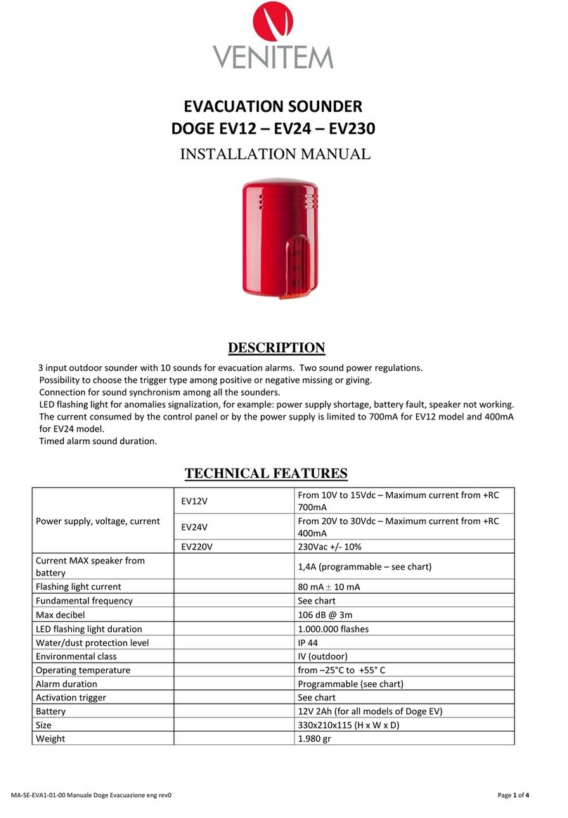
Venitem DOGE EV12 User manual

IT
EN
DOGE EV12
DOGE EV24
DOGE EV230
MANUALE TECNICO
TECHNICAL MANUAL

2
AVVERTENZA
Pressione sonora elevata, rischi di
danni all’udito.
Rischio di esplosione se la batteria è
sostituita con un tipo errato.
ISTRUZIONI DI SICUREZZA IMPORTANTI
Leggere attentamente questa sezione e conservarla
WARNING
High sound pressure, risk of
hearing loss.
Explosion risk if the battery is
replaced with a wrong type.
IMPORTANT SAFETY INSTRUCTIONS
Read the following section carefully and store it

MANUALE TECNICO
3
MONTAGGIO
ATTENZIONE: Per aprire la sirena è necessario spingere verso il basso e
contemporaneamente verso l’esterno la calotta del lampeggiante e svitare la vite.
1. Fissare la sirena al muro.
2. Inserire i cavi passandoli attraverso i fori della base.
3. Se necessario modificare il settaggio dei DIP Switch
seguendo le tabelle precedenti.
4. Collegare i cavi alla centrale di allarme.
5. Chiudere il coperchio interno e il coperchio esterno
utilizzando le viti fornite.
DOGE EV12 - DOGE EV24 - DOGE EV230
SIRENA EVACUAZIONE
CARATTERISTICHE
Sirena da esterno a 3 ingressi e 10 suoni per allarmi di evacuazione. Due regolazioni di potenza
del suono. Possibilità di comando positivo oppure negativo a mancare o a dare. Collegamento
per sincronizzare il suono tra le sirene. Lampeggiante con LED di segnalazione anomalie, ad
es. mancanza alimentazione, batteria guasta, tromba non funzionante. Corrente assorbita dalla
centrale o dall’alimentatore limitata a 700 mA per EV12 e 400 mA per EV24.
Temporizzazione della durata dell’allarme sonoro. Protezione della programmazione.
Asole di fissaggio
IMPORTANTE
Per evitare la formazione di condensa nella
sirena si deve impedire qualsiasi flusso d’aria
nella canalina. Passare il cavo nel dischetto
in neoprene a cellule chiuse (fornito nel kit
viti) interponendolo tra il muro e il fondo della
sirena. Questa operazione evita che durante il
periodo invernale, l’aria calda e umida che esce
dall’edificio possa entrare nella sirena e vada
a formare condensa precludendo il corretto
funzionamento della sirena stessa.
ATTENZIONE: l’alimentazione deve essere di tipo SELV.

4
SCHEMA DI COLLEGAMENTO
CONNESSIONE 3 SUONI CON COMANDO NEGATIVO A DARE E INVERSIONE DI POLARITÀ
Collegare l’alimentazione a 12 Vcc o 24 Vcc ai morsetti di ricarica S1/RC (Ricarica) 1 e 2.
Collegare la resistenza di fine linea della centrale antincendio ai morsetti 4 e 5.
Collegare gli ingressi 3 e 5 alla centrale antincendio a inversione di polarità.
Collegare gli ingressi 7 e 9 come nella figura seguente con DIP7 = ON e DIP 8 = ON
CONNESSIONE 3 SUONI CON COMANDO NEGATIVO A DARE
Collegare l’alimentazione a 12 Vcc o 24 Vcc ai morsetti di ricarica S1/RC (Ricarica) 1 e 2.
Collegare gli ingressi 5, 7 e 9 come nella figura seguente con DIP7 = ON e DIP 8 = ON
NB: NEL CASO LA SIRENA SIA CONFIGURATA CON COMANDO A MANCARE E NON VENGANO
UTILIZZATI TUTTI E 3 GLI INGRESSI COLLEGARE GLI INGRESSI NON USATI AL NEGATIVO/POSITIVO
IN BASE AL DIP 7.
+12 Vcc / + 24 Vcc
+12 Vcc / + 24 Vcc

MANUALE TECNICO
5
MORSETTI
MORSETTI CONNESSIONI
+ S1/RC (1) Ricarica batteria 12 Vcc (EV12 e EV230) o 24 Vcc (EV24)
- S1/RC (2) Ricarica batteria 0 Vcc
+S2 (3) Relè anomalia 100 mA / 48 Vcc MAX
R (4) Relè anomalia 100 mA / 48 Vcc MAX
-S2 R (5) Ingresso comando evacuazione 1
+ S3 (6) Uscita positiva +12 Vcc utilizzabile per comandare gli ingressi
- S3 (7) Ingresso comando evacuazione 2
(8) Sincronismo
(9) Ingresso comando evacuazione 3
MORSETTI SU TL1207
0 - 230 Alimentazione su Doge EV230
J1 Connettore batteria
e tromba
J2 Connettore
lampeggiante
TAB. 1

6
LD1 LED
ANOMALIA
COLLEGAMENTO SINCRONISMO
COLLEGAMENTO ANOMALIA LED
1 KOhm
LED acceso = Nessuna anomalia

MANUALE TECNICO
7
COLLEGAMENTO DUE PULSANTI VERSO MASSA E SINCRONISMO TRA DUE SIRENE
COLLEGAMENTO DUE PULSANTI VERSO POSITIVO E SINCRONISMO TRA DUE SIRENE
ALIMENTATORE ALIMENTATORE
220 Vca 220 Vca
PULSANTE
ALLARME
PULSANTE
ALLARME
DIP7 ON Comando negativo (0 Vcc)
DIP8 ON Comando a dare
DIP7 ON Comando positivo (+12 Vcc o +24 Vcc)
DIP8 ON Comando a mancare
ALIMENTATORE ALIMENTATORE
220 Vca 220 Vca
PULSANTE
ALLARME
PULSANTE
ALLARME

8
IMPOSTAZIONE DIP-SWITCH
TAB. 3: TEMPORIZZAZIONE ALLARME
TAB. 5: SUONI EVACUAZIONE DIP 4, 5, 6
I DIP possono essere modificati solo nelle prime 12 ore dopo l’alimentazione della sirena,
realizzata con la batteria o tramite il morsetto + S1/RC (1). Successivamente perché la modifica
della posizione dei DIP abbia effetto bisogna disalimentare la sirena scollegando la batteria e il
morsetto + S1/RC (1).
DIP FUNZIONE
DIP 1 Temporizzazione allarme
DIP 2 Temporizzazione allarme
DIP 3 Stato impianto
DIP 4 Potenza e corrente assorbita
DIP 5 Selezione gruppo di suoni
DIP 6 Selezione gruppo di suoni
DIP 7 Polarità Comando, positivo o negativo
DIP 8 Transizione Comando a mancare o dare
DIP 3 FUNZIONE
OFF LED Stato impianto Spenti
ON LED Stato impianto accesi se non ci sono anomalie
DIP 1 DIP 2 TEMPORIZZAZIONE
ALLARME
OFF OFF INFINITO
ON OFF 3 MINUTI
OFF ON 8 MINUTI
ON ON 15 MINUTI
DIP
4
DIP
5
DIP
6
EV1
Morsetto 5
(dBA @ 1 m)
EV2
Morsetto 7
(dBA @ 1 m)
EV3
Morsetto 9
(dBA @ 1 m)
Corrente
MAX dalla
batteria
OFF OFF OFF DIN33 calante
(112,8 dB)
NFS32
Doppio tono (106 dB)
ISO8021 - 3 Impulsi
+ pausa (97,4 dB) 1.700 mA
ON OFF OFF DIN33 calante
(112,8 dB)
NFS32
Doppio tono (106 dB)
ISO8021 - 3 Impulsi
+ pausa (97,4 dB) 1.100 mA
OFF OFF ON BS5839 Doppio tono
(104,4 dB)
NEN2575
Crescente + pausa
(113 dB)
Continuo (106,4 dB) 1.700 mA
ON OFF ON BS5839 Doppio tono
(104,4 dB)
NEN2575
Crescente + pausa
(112 dB)
Continuo (105,4 dB) 1.100 mA
OFF ON OFF Continuo 610 Hz
(103,3 dB)
Impulsato 610 Hz
(98,4 dB)
Due toni 610Hz –
490Hz (103,9 dB) 1.600 mA
OFF ON ON Campana 1.200 Hz
(118,6 dB)
Impulsato 610 Hz
(99,5 dB)
Due toni 610 Hz –
490Hz (104,5 dB) 1.600 mA
TAB. 2 - DIP SWITCH
TAB. 4: FUNZIONE DEI LED DI STATO IMPIANTO

MANUALE TECNICO
9
SINCRONISMO
ANOMALIE
TAB. 8: ANOMALIE
Quando si usa il sincronismo è necessario impostare lo stesso suono e la stessa temporizzazione
dell’allarme su tutte le sirene per evitare malfunzionamenti.
Quando la tensione della batteria è inferiore a 9,5 Vcc la sirena non emette nessun suono e non
attiva il lampeggiante per evitare segnalazioni errate. Quando la batteria si riporta a 10,5 Vcc la
sirena riprende il funzionamento normale.
Alla prima alimentazione il lampeggiante accende i LED per segnalare l’alimentazione e
permettere la verifica del funzionamento del lampeggiante.
I LED di stato impianto lampeggiano solo se non ci sono anomalie, in caso contrario i due
LED non lampeggiano ed è necessario aprire la sirena per osservare il LED interno e contare
i lampeggi, vedi tabella 8. Il LED interno di segnalazione anomalie tiene memoria della prima
anomalia che viene riscontrata, la memoria è cancellata quando si attiva un allarme per
almeno un secondo. Questo permette all’installatore, nel caso di un’anomalia instabile come
una batteria guasta, di verificare cosa ha generato l’ anomalia anche se la causa è scomparsa.
Il lampeggiante della sirena mantiene la memoria (quindi non lampeggia) come il LED anomalie
eccetto per la mancanza rete che non viene memorizzata.
DIP 7 POLARITÀ
OFF Comando positivo (+12 Vcc o +24 Vcc)
ON Comando negativo (0 Vcc)
DIP 8 CAMBIAMENTO
OFF Comando a mancare
ON Comando a dare
ANOMALIE LED LD1 CONTATTO RELÈ
MORSETTI 3 E 4
Interruzione Speaker (test ogni 10 s) 1 LAMPEGGIO APERTO
Mancanza corrente di ricarica (V ricarica < 12 Vcc su
EV12 e EV230, V ricarica < 19 V su EV24) (test ogni 10 s) 2 LAMPEGGI APERTO
Batteria sconnessa (test ogni 4 ore) 3 LAMPEGGI APERTO
Batteria bassa tensione (V batteria < 10,5 Vcc)
(test ogni 10 s) 4 LAMPEGGI APERTO
Batteria deteriorata – resistenza superiore a 2,5 Ohm
(test ogni 4 ore) 5 LAMPEGGI APERTO
Nessuna anomalia OFF CHIUSO
TAB. 6: DIP 7 POLARITÀ COMANDO TAB. 7: DIP 8 TIPO DI COMANDO
Priorità suoni: Attenzione La priorità degli ingressi è (5), (7) e per ultimo (9).
Questo vuol dire che se tutti gli ingressi sono collegati contemporaneamente a 0 Vcc (con DIP
7 e DIP 8 ON) verrà generato il suono (5).

10
Alimentazione, tensione e
corrente
EV12 Vcc Da 10 Vcc a 15 Vcc
Corrente massima da +RC 700 mA
EV24 Vcc Da 20 Vcc a 30 Vcc
Corrente massima da +RC 400 mA
EV230 Vca 230 Vca +/- 10%
Corrente MAX tromba da batteria 1,7 Ah (programmabile – vedi tabella 5)
Corrente lampeggiante 80 mA ± 10 mA
Frequenza fondamentale Vedi tabella 5
Decibel Max 109 dB @ 3 m
Durata LED del Flash 1.000.000 lampeggi
Grado protezione polvere/acqua IP 44
Grado ambientale IV (outdoor)
Temperatura di funzionamento da –25 °C a +55 °C
Tempo di durata allarme Programmabile (vedi tabella 3)
Comando di attivazione Vedi tabella 6
Batteria da utilizzare 12 Vcc 2 Ah (per tutti i modelli di Doge EV)
Dimensioni 330x210x115 (A x L x P)
Peso 2.247 gr EV12/EV24
2.733 gr EV230
Conforme alla norma CEI EN 50849:2018-01 Sistemi di allarme
sonoro per applicazioni di emergenza
ALIMENTAZIONE DA RETE 230 Vca
Tipo: Trasformatore di sicurezza resistente al
cortocircuito
Tensione/Corrente di ingresso 210 ÷ 230 Vca / 100 mA
Tensione/Corrente di uscita 12 Vcc e 13,8 Vcc / 500 mA
Classe isolamento II
CARATTERISTICHE TECNICHE
GARANZIA
Tutti i prodotti Venitem sono garantiti 24 mesi. Nell’intento di migliorare il design e la qualità dei
prodotti la ditta Venitem si riserva di modificare il prodotto senza alcun preavviso. Tutti i prodotti
guasti vanno resi al proprio fornitore.
ATTENZIONE:
Si prega di notare che tutte le indicazioni di installazione qui sopra devono essere attentamente
rispettate per evitare che il dispositivo perda la sua conformità alle norme.

TECHNICAL MANUAL
11
AVVERTENZA
Pressione sonora elevata, rischi di
danni all’udito.
Rischio di esplosione se la batteria è
sostituita con un tipo errato.
ISTRUZIONI DI SICUREZZA IMPORTANTI
Leggere attentamente questa sezione e conservarla
WARNING
High sound pressure, risk of
hearing loss.
Explosion risk if the battery is
replaced with a wrong type.
IMPORTANT SAFETY INSTRUCTIONS
Read the following section carefully and store it

12
SOUNDER INSTALLATION
ATTENTION: To open the sounder, it is necessary to push the cover downwards and
outwards at the same time and unscrew the screw.
1. Fix the Sounder on the wall.
2. Insert the cables through the holes on its base.
3. If necessary, modify the DIP Switch setting following the
previous charts.
4. Connect the cables to the control panel.
5. Close the internal cover and the external one using the
screws supplied.
DOGE EV12 - DOGE EV24 - DOGE EV230
EVACUATION SOUNDER
DESCRIPTION
3 input outdoor sounder with 10 sounds for evacuation alarms. Two sound power regulations.
Possibility to choose the trigger type among positive or negative missing or giving. Connection
for sound synchronism among all the sounders. LED flashing light for anomalies signalization,
for example: power supply shortage, battery fault, speaker not working. The current consumed
by the control panel or by the power supply is limited to 700 mA for EV12 model and 400 mA
for EV24 model. Timed alarm sound duration.
Fixing holes
IMPORTANT
To prevent condensation formation in the sounder,
it is important to avoid any air flow inside the duct.
To such purpose, run the cable in the closed cell
neoprene disc (provided in the screw kit), by placing
it between wall and sounder base. This operation
prevents condensation from forming inside the
sounder; condensation mostly appears in winter
and it is usually caused by warm and humid air
coming out of the wall where the sounder is
installed and passing through the hole located
on the sounder base.
ATTENTION: power supply must be of SELV type.

TECHNICAL MANUAL
13
SOUND 1
SOUND 2
SOUND 3
CONTROL
PANEL
CONNECTION SCHEME
NEGATIVE GIVING TRIGGER AND POLARITY INVERSION 3 SOUNDS CONNECTION
Connect the 12 Vdc or 24 Vdc power supply to the recharging terminals S1/RC (Recharge) 1 and 2.
Connect the end line resistance coming from the fire control panel to the terminals 4 and 5.
Connect in polarity inversion the inputs 3 and 5 to the fire control panel. Connect inputs 7 and
9 as shown in the picture below. DIP7 = ON and DIP 8 = ON
NEGATIVE GIVING TRIGGER 3 SOUND CONNECTION
Connect the 12 Vdc or 24 Vdc power supply to the recharging terminals S1/RC (Recharge) 1 and 2.
Connect inputs 5,7 and 9 with DIP7 = ON and DIP8 = ON, as shown in the picture below.
ATTENTION: IN CASE THE SOUNDER IS SET WITH MISSING TRIGGER AND ONE OR MORE OF THE
THREE INPUTS ARE NOT USED, CONNECT THE INPUTS THAT ARE NOT USED TO THE NEGATIVE/
POSITIVE, FOLLOWING DIP 7
SOUND 1
SOUND 2
SOUND 3
CONTROL
PANEL
POLARITY
INVERSION
+12 Vdc / + 24 Vdc
+12 Vdc / + 24 Vdc

14
TERMINALS
TERMINALS TERMINALS
+ S1/RC (1) 12 Vdc battery recharge (EV12 and EV230) or 24 Vdc (EV24)
- S1/RC (2) Battery recharge 0 Vdc
+S2 (3) Relay anomaly 100 mA / 48 Vdc MAX
R (4) Relay anomaly 100 mA / 48 Vdc MAX
-S2 R (5) Evacuation command 1 input
+ S3 (6) +12 Vdc positive output used to trigger the inputs
- S3 (7) Evacuation command 2 input
(8) Syncronism
(9) Evacuation command 3 input
TERMINALS ON TL1207
0 - 230 Power supply on doge EV230
J2 LED Connection
J1 Battery and speaker
Connection
CHART. 1

TECHNICAL MANUAL
15
LD1 ANOMALY
LED
SYNCHRONISM CONNECTION
LED ANOMALY CONNECTION
1 KOhm
LED on = No Anomaly

16
CONNECTION TWO BUTTONS TO NEGATIVE AND SYNCHRONISM BETWEEN TWO SIRENS
CONNECTION TWO BUTTONS TO POSITIVE AND SYNCHRONISM BETWEEN TWO SIRENS
POWER SUPPLY POWER SUPPLY
220 Vac 220 Vac
ALARM
BUTTON
ALARM
BUTTON
DIP7 ON Negative trigger (0 Vdc)
DIP8 ON Giving trigger
DIP7 ON Positive trigger (+12 Vdc o +24 Vdc)
DIP8 ON Missing trigger
POWER SUPPLY POWER SUPPLY
220 Vac 220 Vac
ALARM
BUTTON
ALARM
BUTTON

TECHNICAL MANUAL
17
DIP-SWITCH SETTING
TAB. 3: ALARM TIMING
TAB. 5: SOUNDS DIP 4, 5, 6
DIP switches can be moved only within the first 12 hours after the board is powered. After
this period, DIP switches Settings will be stored and any further switching will be useless. By
disconnecting battery and power supply, DIP switches will return to active for another 12 hours.
DIP FUNCTION
DIP 1 Alarm timing
DIP 2 Alarm timing
DIP 3 System status
DIP 4 Consumed power and current
DIP 5 Sounds group selection
DIP 6 Sounds group selection
DIP 7 Trigger polarity, positive or negative
DIP 8 Transition giving or missing trigger
DIP 3 FUNCTION
OFF System Status LEDs Off
ON System Status LEDs On if no anomalies
DIP 1 DIP 2 ALARM TIMING
OFF OFF INFINITE
ON OFF 3 MINUTES
OFF ON 8 MINUTES
ON ON 15 MINUTES
DIP
4
DIP
5
DIP
6
EV1
Terminal 5
(dBA @ 1 m)
EV2
Terminal 7
(dBA @ 1 m)
EV3
Terminal 9
(dBA @ 1 m)
MAX
current
from the
battery
OFF OFF OFF DIN33 descending
(112.8 dB)
NFS32
Double tone
(106 dB)
ISO8021 - 3 Pulses
+ pause (97.4 dB) 1,700 mA
ON OFF OFF DIN33 descending
(112.8 dB)
NFS32
Double tone
(106 dB)
ISO8021 - 3 Pulses
+ pause (97.4 dB) 1,100 mA
OFF OFF ON BS5839 Double
tone (104.4 dB)
NEN2575
Ascending + pause
(113 dB)
Continuous
(106.4 dB) 1,700 mA
ON OFF ON BS5839 Double
tone (104.4 dB)
NEN2575
Ascending + pause
(112 dB)
Continuous
(105.4 dB) 1,100 mA
OFF ON OFF Continuous 610 Hz
(103.3 dB)
Pulsed 610 Hz
(98.4 dB)
Two tones 610Hz –
490Hz (103.9 dB) 1,600 mA
OFF ON ON Bell-type 1.200 Hz
(118.6 dB)
Pulsed 610 Hz
(98.4 dB)
Two tones 610Hz –
490Hz (104.5 dB) 1,600 mA
TAB. 2 - DIP SWITCH
TAB. 4: SYSTEM STATUS LED FUNCTION

18
SYNCHRONISM
ANOMALIES
TAB. 8: ANOMALIES
When synchronism is activated, it is necessary to set the same alarm sound and the same
timing in all the sounders in order to avoid malfunctions.
When battery voltage is lower than 9,5 Vdc, the sounder does not produce any sound and does
not activate the flashing light in order to avoid wrong warnings. When the battery goes up to
10,5 Vdc again, the sounder operates normally.
At its first power, the flashing light turns on the LEDs to signal the power supply and to allow
the flashing light operation to be checked.
The system status LEDs flash only if there are no faults, otherwise the two LEDs will not blink
and it is necessary to open the sounder to observe the internal LED and count the flashes, see
chart 8.
DIP 7 POLARITY
OFF Positive trigger (+12 Vdc or +24 Vdc)
ON Negative trigger (0 Vdc)
DIP 8 CHANGE
OFF Missing trigger
ON Giving trigger
ANOMALIES LED LD1 CONTATTO RELÈ
MORSETTI 3 E 4
Speaker interruption (test every 10 s) 1 FLASH OPEN
Recharge current is missing (V recharge < 12 Vdc on
EV12 and EV230, V recharge < 19 Vdc on EV24)
(test every 10 s)
2 FLASHES OPEN
Disconnected battery (test every 4 hours) 3 FLASHES OPEN
Low voltage battery (V battery < 10,5 Vdc)
(test every 10 s) 4 FLASHES OPEN
Deteriorated battery – resistance higher than 2,5 Ohm
(test every 4 hours) 5 FLASHES OPEN
No anomalies OFF CLOSED
CHART 6: DIP 7 TRIGGER POLARITY TAB. 7: DIP 8 TRIGGER TYPE
Sound priority: Attention! The input priority is (5), (7) and lastly (9).
This means that if all the input are connected simultaneously to 0 Vdc (with DIP 7 and DIP 8
ON), the sound starts (5).

TECHNICAL MANUAL
19
WARRANTY
All Venitem products are granted against factory or material defects. In order to improve design
and quality of the products, Venitem reserves the right to modify them without prior notice. All
faulty or defective items must be returned to the supplier.
ATTENTION:
Please note that all installation indications here above must be carefully respected to prevent
the device from loosing its standard compliance.
Power supply, voltage, current
EV12 Vdc From 10 Vdc to 15 Vdc
Maximum current from +RC 700 mA
EV24 Vdc From 20 Vdc to 30 Vdc
Maximum current from +RC 400 mA
EV230 Vac 230 Vac +/- 10%
Current MAX speaker from battery 1,7 Ah (programmable – see chart 5)
Flashing light current 80 mA ± 10 mA
Fundamental frequency See chart 5
Max decibel 109 dB @ 3 m
LED flashing light duration 1,000,000 flashes
IP reating IP 44
Environmental class IV (outdoor))
Operating temperature from –25 °C to +55 °C
Alarm duration Programmable (see chart 3)
Activation trigger See chart 6
Battery 12 Vdc 2 Ah (for all models of Doge EV)
Size 330x210x115 mm (H x W x D)
Weight 2,247 gr EV12 / EV24
2,733 gr EV230
Standard compliance CEI EN 50849:2018-01 Sound alarm
systems for emergency applications
MAINS 230 Vac
Type Short-circuit proof safety transformer
Input voltage / current 210 ÷ 230 Vac / 100 mA
Output voltage / current 12 Vdc e 13.8 Vdc / 500 mA
Isolatin class II
TECHNICAL FEATURES

Sede legale e operativa / Headquarters:
Via del Lavoro, 10 30030 Salzano (VE) - Italy
Tel. +39.041.5740374 - Fax +39.041.5740388
AZIENDA CERTIFICATA
MA-SE-EVA1-02-11
This manual suits for next models
2
Table of contents
Languages:
Other Venitem Marine Equipment manuals

Venitem
Venitem DOGE EV12 User manual

Venitem
Venitem HOLA F24EN User manual

Venitem
Venitem DOGE AS1 User manual

Venitem
Venitem MINI DOGE User manual

Venitem
Venitem SP200 User manual

Venitem
Venitem ONDA User manual

Venitem
Venitem RIO L User manual

Venitem
Venitem MINI MARINA L User manual

Venitem
Venitem HEMA L User manual

Venitem
Venitem RIALTO L Guide