manuals.online logo
Brands
  1. Home
  2. •
  3. Brands
  4. •
  5. Venitem
  6. •
  7. Marine Equipment
  8. •
  9. Venitem DOGE EV12 User manual

Venitem DOGE EV12 User manual

MA-SE-EVA1-01-00 Manuale Doge Evacuazione eng rev0 Page 1of 4
EVACUATION SOUNDER
DOGE EV12 –EV24 –EV230
INSTALLATION MANUAL
DESCRIPTION
3 input outdoor sounder with 10 sounds for evacuation alarms. Two sound power regulations.
Possibility to choose the trigger type among positive or negative missing or giving.
Connection for sound synchronism among all the sounders.
LED flashing light for anomalies signalization, for example: power supply shortage, battery fault, speaker not working.
The current consumed by the control panel or by the power supply is limited to 700mA for EV12 model and 400mA
for EV24 model.
Timed alarm sound duration.
TECHNICAL FEATURES
Power supply, voltage, current
EV12V
From 10V to 15Vdc –Maximum current from +RC
700mA
EV24V
From 20V to 30Vdc –Maximum current from +RC
400mA
EV220V
230Vac +/- 10%
Current MAX speaker from
battery
1,4A (programmable –see chart)
Flashing light current
80 mA 10 mA
Fundamental frequency
See chart
Max decibel
106 dB @ 3m
LED flashing light duration
1.000.000 flashes
Water/dust protection level
IP 44
Environmental class
IV (outdoor)
Operating temperature
from –25°C to +55° C
Alarm duration
Programmable (see chart)
Activation trigger
See chart
Battery
12V 2Ah (for all models of Doge EV)
Size
330x210x115 (H x W x D)
Weight
1.980 gr
MA-SE-EVA1-01-00 Manuale Doge Evacuazione eng rev0 Page 2of 4
CONNECTION SCHEME
ATTENTION: IN CASE THE SOUNDER IS SET WITH MISSING TRIGGER AND ONE OR MORE OF THE
THREE INPUTS ARE NOT USED, CONNECT THE INPUTS THAT ARE NOT USED TO THE
NEGATIVE/POSITIVE, FOLLOWING DIP 7
TERMINALS and DIP-SWITCH SETTING
Chart 1
Terminals
Connections
+ S1/RC (1)
12V battery recharge (EV12 and EV230)
or 24V (EV24)
- S1/RC (2)
Battery recharge 0V
+S2 (3)
Relay anomaly 100mA/ 48V MAX
R (4)
Relay anomaly 100mA/ 48V MAX
-S2 R (5)
Evacuation command 1 input
+ S3 (6)
+12V positive output used to trigger the
inputs
- S3 (7)
Evacuation command 2 input
(8)
Syncronism
(9)
Evacuation command 3 input
Terminals on TL1207
0 - 230
Power supply for Doge EV230
Table 2 DIP SWITCH
DIP
Function
DIP1
Alarm timing
DIP2
Alarm timing
DIP3
System status
DIP4
Consumed power and current
DIP5
Sounds group selection
DIP6
Sounds group selection
DIP7
Trigger polarity, positive or negative
DIP8
Transition giving or missing trigger
ON
OFF
J1 Battery and
speaker
Connection
J2 LED
Connection
NEGATIVE GIVING TRIGGER 3
SOUND CONNECTION
Connect the 12Vcc or 24Vcc power supply to the
recharging terminals S1/RC (Recharge) 1 and 2.
Connect inputs 5,7,9 with DIP7 = ON and DIP8 =
ON, as shown in the picture below
NEGATIVE GIVING TRIGGER AND
POLARITY INVERSION 3 SOUNDS
CONNECTION
Connect the 12Vcc or 24Vcc power supply to the
recharging terminals S1/RC (Recharge) 1 and 2.
Connect the end line resistance coming from the fire
control panel to the terminals 4 and 5. Connect in
polarity inversion the inputs 3, 5 to the fire control
panel. Connect 7 and 9 as shown in the picture below.
DIP7 = ON and DIP 8 = ON
MA-SE-EVA1-01-00 Manuale Doge Evacuazione eng rev0 Page 3of 4
LED on =
No Anomaly
Chart 5: Sounds DIP 4, 5, 6
Sound priority: Attention! The input priority is (5), (7) and lastly (9).
This means that if all the input are connected simultaneously to 0V (with DIP 7 and DIP 8 ON), the sound
starts (5).
Table 8: Anomalies
Chart 4: System status LED Function
DIP 3
Function
OFF
System Status LEDs Off
ON
System Status LEDs On if no anomalies
Chart 3: Alarm timing
DIP 1
DIP 2
ALARM TIMING
OFF
OFF
INFINITE
ON
OFF
3 MINUTES
OFF
ON
8 MINUTES
ON
ON
15 MINUTES
DIP 4
DIP 5
DIP 6
Terminal (5)
Terminal (7)
Terminal (9)
Current from
the battery
OFF
OFF
OFF
DIN33 descending
NFS32 Double tone
ISO8021 - 3 Pulses + pause
1.700mA
ON
OFF
OFF
DIN33 descending
NFS32 Double tone
ISO8021 - 3 Pulses + pause
1.000mA
OFF
OFF
ON
BS5839 Double tone
NEN2575 Ascending + pause
Continuous
1.800mA
ON
OFF
ON
BS5839 Double tone
NEN2575 Ascending + pause
Continuous
1.200mA
OFF
ON
OFF
Continuous 610Hz
Pulsed 610Hz
Two tones 610Hz –490Hz
900mA
OFF
ON
ON
Bell-type 1.200Hz
Pulsed 610Hz
Two tones 610Hz –490Hz
700mA
Chart 6: DIP 7 trigger polarity
DIP7
Polarity
OFF
Positive trigger (+12V or +24V)
ON
Negative trigger (0V)
Chart 7: DIP 8 Trigger type
DIP8
Change
OFF
Missing trigger
ON
Giving trigger
Anomalies
LED LD1
Relay contact
terminals 3 e 4
Speaker interruption
(test every 10s)
1 FLASH
OPEN
Recharge current is missing (V recharge < 12V)
(test every 10s)
2 FLASHES
OPEN
Disconnected battery (test every 4 hours)
3 FLASHES
OPEN
Low voltage battery (V battery < 10,5V)
(test every 10s)
4 FLASHES
OPEN
Deteriorated battery –resistance higher than 2,5 Ohm
(test every 4 hours)
5 FLASHES
OPEN
No anomalies
OFF
CLOSED
1KOhm
LED Anomaly Connection
Synchronism Connection
LD1
ANOMALY
LED
MA-SE-EVA1-01-00 Manuale Doge Evacuazione eng rev0 Page 4of 4
SYNCHRONISM AND ANOMALIES
When synchronism is activated, it is necessary to set the same alarm sound and the same timing in all the sounders in order to
avoid malfunctions.
When battery voltage is lower than 9,5V, the sounder does not produce any sound and does not activate the flashing light in
order to avoid wrong warnings. When the battery goes up to 10,5V again, the sounder operates normally.
At its first power, the flashing light turns on the LEDs to signal the power supply and to allow the flashing light operation to be
checked.
The system status LEDs flash only if there are no faults, otherwise the two LEDs will not blink and it is necessary to open the
sounder to observe the internal LED and count the flashes, see chart 8.
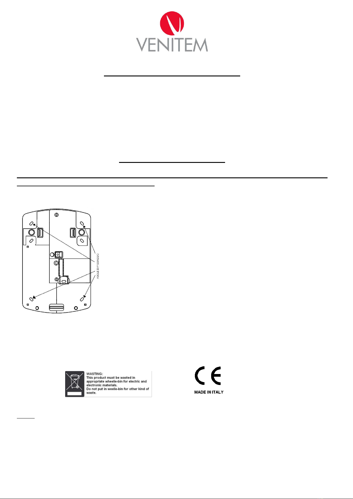
SOUNDER INSTALLATION
Attention. To open the sounder, it is necessary to push the cover downwards and outwards
at the same time and unscrew the screw.
1. Fix the Sounder on the wall.
2. Insert the cables through the holes on its base.
3. If necessary, modify the DIP Switch setting following the previous charts.
4. Connect the cables to the control panel.
5. Close the internal cover and the external one using the screws supplied.
ATTENTION: power supply must be of SELV type.
NOTE: to avoid formation of condensation inside the sounder, any air flow must be avoided. Once the cables have been connected,
seal the hole using some silicone. This operation will prevent the warm and humid air of the building from forming condensation
inside the sounder during winter time, thus avoiding the risk of malfunctioning.
Warranty: All Venitem products have 2 years of guarantee. With the aim of improving design and quality and quality of its products, Venitem reserves the right of
modify them without any notice. All defective products have to be returned to your own supplier.
Venitem s.r.l. Via del Lavoro, 10-30030 Salzano (VE) Tel. (+39) 041 5740374 –Fax (+39) 041 5740388 Web site www.venitem.com E-mail info@venitem.com

This manual suits for next models

2

Other Venitem Marine Equipment manuals

Venitem HOLA F24EN User manual

Venitem

Venitem HOLA F24EN User manual

Venitem DOGE EV12 User manual

Venitem

Venitem DOGE EV12 User manual

Venitem GIUDECCA User manual

Venitem

Venitem GIUDECCA User manual

Venitem RIO L User manual

Venitem

Venitem RIO L User manual

Venitem MINI MARINA L User manual

Venitem

Venitem MINI MARINA L User manual

Venitem DOGE AS1 User manual

Venitem

Venitem DOGE AS1 User manual

Venitem ONDA User manual

Venitem

Venitem ONDA User manual

Venitem SP200 User manual

Venitem

Venitem SP200 User manual

Venitem HEMA L User manual

Venitem

Venitem HEMA L User manual

Venitem RIALTO L Guide

Venitem

Venitem RIALTO L Guide

Venitem TRIADE F24 User manual

Venitem

Venitem TRIADE F24 User manual

Venitem MINI DOGE User manual

Venitem

Venitem MINI DOGE User manual

Popular Marine Equipment manuals by other brands

Furuno FMD-3200 Operator's manual

Furuno

Furuno FMD-3200 Operator's manual

FTGMDC FT-8800 instruction manual

FTGMDC

FTGMDC FT-8800 instruction manual

Dometic KRA Series Installation, operation & maintenance manual

Dometic

Dometic KRA Series Installation, operation & maintenance manual

Jensen MCD5070 Installating and operation manual

Jensen

Jensen MCD5070 Installating and operation manual

Teleflex Marine MV-3 Series installation manual

Teleflex Marine

Teleflex Marine MV-3 Series installation manual

Raymarine ST600R Owner's handbook

Raymarine

Raymarine ST600R Owner's handbook

System Sensor B401BH-2 Installation and maintenance instructions

System Sensor

System Sensor B401BH-2 Installation and maintenance instructions

bamar GFSI CTS instruction manual

bamar

bamar GFSI CTS instruction manual

ABB TPS 48D01 Operation manual

ABB

ABB TPS 48D01 Operation manual

Furuno FICE-100 installation manual

Furuno

Furuno FICE-100 installation manual

Pfannenberg PA 130 Operating and installation instruction

Pfannenberg

Pfannenberg PA 130 Operating and installation instruction

INIM enea ESB1030 manual

INIM

INIM enea ESB1030 manual

IMAGENEX 852-GS user manual

IMAGENEX

IMAGENEX 852-GS user manual

KVH Industries TracNet H90 installation guide

KVH Industries

KVH Industries TracNet H90 installation guide

Furuno FE-800 Operator's manual

Furuno

Furuno FE-800 Operator's manual

Vetus BOWA0761 installation instructions

Vetus

Vetus BOWA0761 installation instructions

Simrad NSS9 evo3S Operator's manual

Simrad

Simrad NSS9 evo3S Operator's manual

Simrad ITI TRAWL EYE - REV D manual

Simrad

Simrad ITI TRAWL EYE - REV D manual

manuals.online logo
manuals.online logoBrands
  • About & Mission
  • Contact us
  • Privacy Policy
  • Terms and Conditions

Copyright 2025 Manuals.Online. All Rights Reserved.