bamar GFSI CTS User manual

GFSI CTS 10
20
30
Via F.lli Lumière 45
47122 Forlì (FC), Italia
Phone: +39 0543 463311
Fax: +39 0543 783319
Email: info@bamar.it
Website: www.bamar.it
Istruzioni di montaggio
Instruction manual
Avvolgifiocco idraulico “flush-deck” per stralli torsionali
“flush-deck” hydraulic foresail furler for torsional stays

INDICE GENERALE
GENERAL INDEX I
A INFORMAZIONI GENERALI............................................. 3
Introduzione ......................................................................... 3
A-1 Simbologia presente nel manuale........................................ 3
A-2 Assistenza............................................................................ 4
A-3 Datidiidenticazione ........................................................... 4
A-3.1 Modello e tipo....................................................................... 4
A-3.2 Costruttore ........................................................................... 4
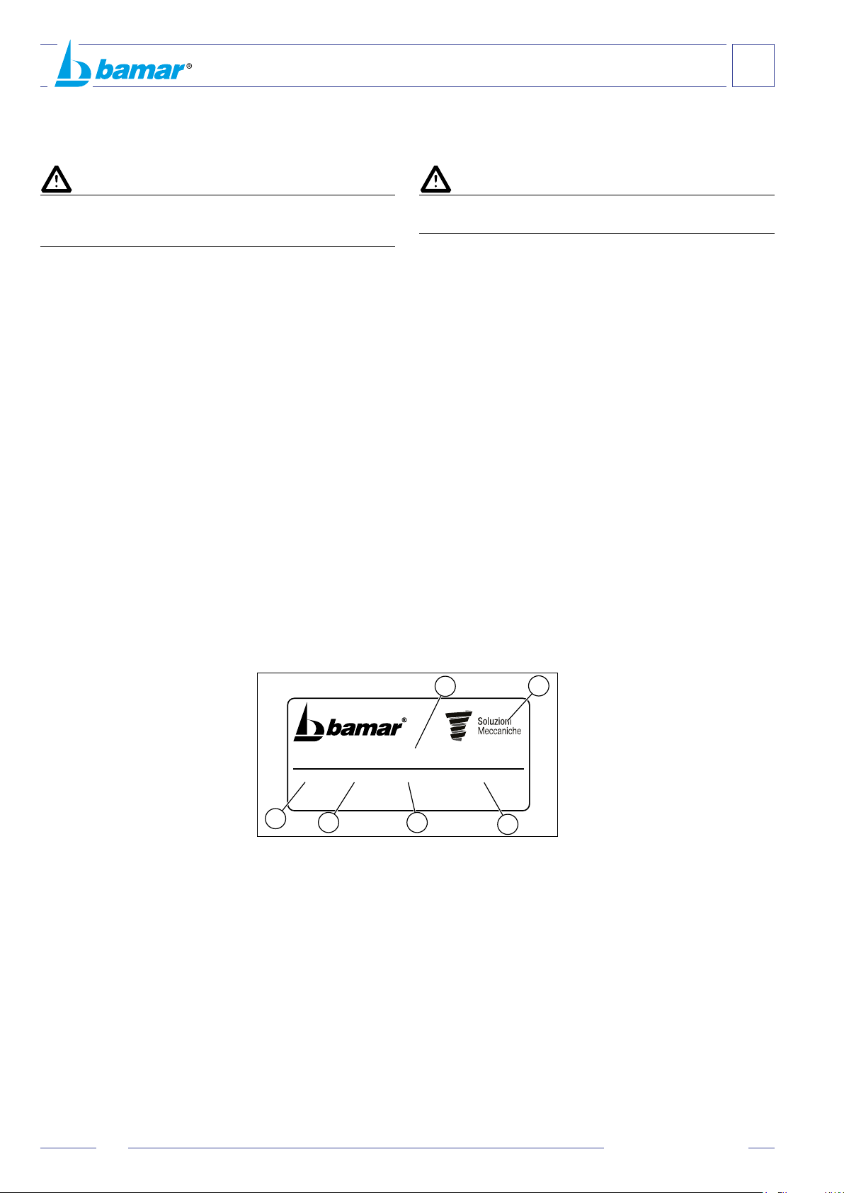
A-3.3 Targhettadiidenticazione................................................... 4
A-4 Descrizionedell’apparecchiatura ......................................... 4
A-5 Imballoecontenuto.............................................................. 5
A-6 Ricevimentodelmateriale.................................................... 5
A-7 Attrezzaturaminimanecessaria........................................... 5
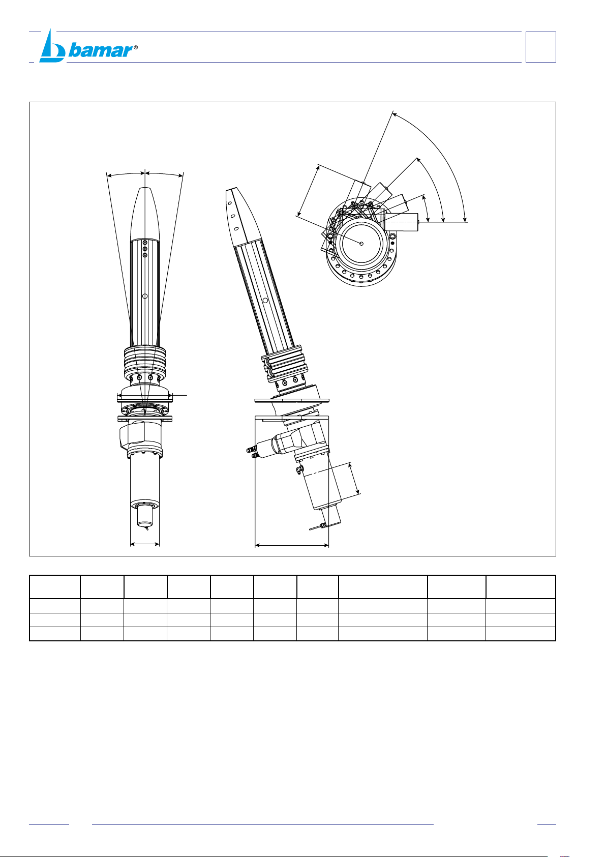
A-8 Datitecnici............................................................................ 6
A-9 Impieghi ammessi ................................................................ 7
A-10 Uso improprio....................................................................... 7
B SICUREZZA......................................................................... 8
B-1 Indicazionigenerali .............................................................. 8
C ISTRUZIONI DI MONTAGGIO .......................................... 9
C-1 Operazioni preliminari .......................................................... 9
C-1.1 Consigli e note ..................................................................... 9
C-1.2 Oliopercilindri ................................................................... 10
C-1.3 Olio per motori.................................................................... 10
C-1.4 Olio per riduttori.................................................................. 11
C-1.5 Grasso per sfera ................................................................ 11
C-2 Tabelladi“tirodelcilindroidraulicointegratoa
sempliceeetto”nell’avvolgioccoidraulicomod.CTS .... 12
C-3 Montaggiodell’avvolgioccointestad’albero.................... 13
C-4 Collegamento dello strallo.................................................. 13
C-5 Montaggioincoperta.......................................................... 14
C-5.1 Rimozione motore .............................................................. 14
C-5.2 Installazione motorizzazione .............................................. 14
C-6 Sensori (optional) ............................................................... 14
C-6.1 Sensoredipressionecilindro(optional)............................. 14
C-6.2 Sensorediposizionecilindro(optional) ............................. 14
C-7 Foriscaricoacqua.............................................................. 15
C-8 Consigliperlavela............................................................. 15
C-9 Montaggiodellavela .......................................................... 15
C-10 Usodell’avvolgiocco......................................................... 15
D MANUTENZIONE............................................................. 16
D-1 Manutenzione..................................................................... 16
D-2 Livellidimanutenzione....................................................... 16
D-3 Programma di manutenzione ............................................. 17
D-3.1 Puliziaelavaggio ............................................................... 17
D-3.2 Lunghi periodi di inutilizzo .................................................. 17
D-3.3 Verichevisive ................................................................... 17
D-3.4 Ingrassaggio trasmissione interna ..................................... 17
D-3.5 Interventidiriparazione...................................................... 17
D-4 Inconvenienti-cause-rimedi ............................................ 17
E ALLEGATI.......................................................................... 18
E-1 Sensoredipressionecilindro............................................. 18
E-2 Sensorediposizionecilindro ............................................. 21
E-2.1 Per CTS 10 e CTS 20 ........................................................ 21
E-2.2 Per CTS 30 ........................................................................ 26
E-3 ForocopertaGFSICTS10 ................................................ 29
E-4 ForocopertaGFSICTS20-30........................................... 30
E-5 Schemavalvoladimassimaperil
controllodelcilindrotendistrallo......................................... 31
GARANZIA ....................................................................... 32
A GENERAL INFORMATION.................................................. 3
Introduction .......................................................................... 3
A-1 Symbols to be found in the manual...................................... 3
A-2 After-sales service................................................................ 4
A-3 Identicationdata ................................................................. 4
A-3.1 Model and type..................................................................... 4
A-3.2 Manufacturer ........................................................................ 4
A-3.3 Identicationplate ................................................................ 4
A-4 Description of the equipment ............................................... 4
A-5 Packaging and content......................................................... 5
A-6 Receipt of goods .................................................................. 5
A-7 Basic tools............................................................................ 5
A-8 Technical data ...................................................................... 6
A-9 Proper use............................................................................ 7
A-10 Wrong use............................................................................ 7
B SAFETY ............................................................................... 8
B-1 General indications .............................................................. 8
C INSTALLATION .................................................................. 9
C-1 Preliminary operations ......................................................... 9
C-1.1 Suggestions and notes......................................................... 9
C-1.2 Cylinder oil ......................................................................... 10
C-1.3 Motors oil............................................................................ 10
C-1.4 Reduction gear oil .............................................................. 11
C-1.5 Grease for spherical connections....................................... 11
C-2 Loadtableforthehydraulicsingleeect
cylinder integrated in hydraulic furler mod. CTS ................ 12
C-3 How to install the furler onboard ........................................ 13
C-4 How to connect the turnbuckle........................................... 13
C-5 Installation on deck ............................................................ 14
C-5.1 How to remove the motor................................................... 14
C-5.2 How to install the motorization ........................................... 14
C-6 Sensors (optional) .............................................................. 14
C-6.1 Cylinder pressure sensor (optional) ................................... 14
C-6.2 Cylinder position sensor (optional)..................................... 14
C-7 Water drain holes ............................................................... 15
C-8 Suggestions for the sail...................................................... 15
C-9 How to hoist the sail ........................................................... 15
C-10 How to use the furler .......................................................... 15
D MAINTENANCE................................................................. 16
D-1 Maintenance....................................................................... 16
D-2 Maintenance levels ............................................................ 16
D-4 Troubleshooting.................................................................. 17
D-3 Maintenance programme ................................................... 17
D-3.1 Cleaning and washing........................................................ 17
D-3.2 Long inactivity .................................................................... 17
D-3.3 Visual check ....................................................................... 17
D-3.4 Gearbox greasing............................................................... 17
D-3.5 Repair................................................................................. 17
E ATTACHMENT.................................................................. 18
E-1 Cylinder pressure sensor ................................................... 18
E-2 Cylinder position sensor..................................................... 21
E-2.1 For CTS 10 and CTS 20 .................................................... 21
E-2.2 For CTS 30......................................................................... 26
E-3 GFSI CTS 10 Deck hole..................................................... 29
E-4 GFSI CTS 20-30 Deck hole ............................................... 30
E-5 Max pressure relief valve scheme...................................... 31
WARRANTY....................................................................... 32
© Copyright Soluzioni Meccaniche srl
Tuttiidirittiriservati
Stampato in Italia
Realizzazione:SoluzioniMeccanichesrl-Forlì
Questomanualeopartidiessononpossonoessereriprodotti,copiatio
divulgaticonqualsiasimezzosenzalapreventivaautorizzazionescritta
delladittaSoluzioniMeccaniches.r.l.
La ditta Soluzioni Meccaniche s.r.l. si riserva il diritto di apportare in
qualsiasimomentotuttelemodichecheriterràopportune,nellacostante
ricercadimigliorarelaqualitàelasicurezzadelleattrezzature,senza
impegnarsiadaggiornaredivoltainvoltaquestapubblicazione.
© Copyright Soluzioni Meccaniche srl
All rights reserved
Printed in Italy
Realization: Soluzioni Meccaniche srl - Forlì
No part of this manual may be reproduced, copied or transmitted in
any form, or by any means without permission in writing from Soluzioni
Meccaniche srl
Soluzioni Meccaniche srl has the right to make any changes they think
necessary in order to improve the quality and safety of the systems,
without being obliged to revise this publication every time.
2um_cts_it-en_rev. 05/2022

INTRODUCTION
This manual has been realised in order to supply all required information
for a correct and safe installation, use and maintenance of the equipment.
You have to read and
understand this manual before using
the equipment and carrying out any
operation on it.
This manual has been divided into sections, chapters and paragraphs in
order to present the information in a structured and clear way.
Pages are numbered progressively.
The search for information may be done either through the key words used
as titles for the sections, or through the consultation of the general index.
Keep this manual at hand even after having read it, it may help clarify
any doubt.
Should you have problems in understanding this manual or parts of it,
we strongly recommend contacting Soluzioni Meccaniche srl: address,
phone and fax number can be found on the cover.
Soluzioni Meccaniche srl declines any and every responsibility
for damages to persons or things caused by either an improper
use of the system or inexperience, negligence, imprudence, or
non-compliance with this manual.
A-1 SYMBOLS TO BE FOUND IN THE MANUAL
Five “graphic safety symbols” are used in this manual. Their purpose is
tohighlightdierentlevelsofdangerand/orinformation:
DANGER
DANGER OF ELECTROCUTION
CAUTION
WARNING
RESPECT THE ENVIRONMENT
Draws one’s attention to situations or problems that might endanger the
safety of persons, causing the risk of accident and death.
DANGER
DANGER OF ELECTROCUTION
CAUTION
WARNING
RESPECT THE ENVIRONMENT
Draws one’s attention to a highly dangerous situation that might endanger
the safety and life of exposed persons due to the presence of electricity.
DANGER
DANGER OF ELECTROCUTION
CAUTION
WARNING
RESPECT THE ENVIRONMENT
Draws one’s attention to situations or problems linked to the system’s
eciencywhichdonotendangerthesafetyofpeople.
DANGER
DANGER OF ELECTROCUTION
CAUTION
WARNING
RESPECT THE ENVIRONMENT
Draws one’s attention to important general information that endangers
neither personal safety nor the operation of the system.
DANGER
DANGER OF ELECTROCUTION
CAUTION
WARNING
RESPECT THE ENVIRONMENT
Draws one’s attention to important pieces of information concerning
respect for the environment.
INTRODUZIONE
Questomanualeèstatorealizzatoalloscopodiforniretutteleinformazioni
necessarie per installare ed utilizzare l’apparecchiatura in maniera
correttaesicuraepereettuarnelamanutenzione.
Occorre leggere e capire questo manuale
prima di usare l’apparecchiatura,
ed eettuare qualsiasi operazione
con esso o su di esso.
Il manuale è suddiviso in sezioni, capitoli e paragrafi in modo da
presentareleinformazionistrutturateinmodochiaro.
Lepaginesononumerateprogressivamente.
Laricercadelleinformazionipuòesserebasatasull’utilizzodelleparole
chiaveusatecometitolodellesezioniedeicapitolimasoprattuttodalla
consultazionedell’indicegenerale.
Conservarequestomanualeanchedopolacompletalettura,inmodo
chesiasempreaportatadimanoperilchiarimentodieventualidubbi.
Incasodiprobleminellacomprensionediquestomanualeodipartidi
essosiraccomandavivamentedicontattareladittaSoluzioniMeccaniche
srl:indirizzi,numeri ditelefonoetelefaxsonoriportatinella quartadi
copertinadiquestomanuale.
La ditta Soluzioni Meccaniche srl declina ogni responsabilità
per danni a persone o cose derivanti da un uso improprio
dell’attrezzatura, da imperizia, imprudenza o negligenza e dalla
inosservanza delle norme descritte in questo manuale.
A-1 SIMBOLOGIA PRESENTE NEL MANUALE
In questo manuale sono utilizzati cinque tipi di “simboli grafici di
sicurezza”,chehannoloscopodievidenziarealtrettantilivellidipericolo
o informazione:
PERICOLO
PERICOLO DI FOLGORAZIONE
ATTENZIONE
AVVERTENZA
RISPETTA L'AMBIENTE
Richiamal’attenzioneasituazionioproblemichepotrebberopregiudicare
l’incolumitàdellepersoneperinfortuniorischiodimorte.
PERICOLO
PERICOLO DI FOLGORAZIONE
ATTENZIONE
AVVERTENZA
RISPETTA L'AMBIENTE
Richiamal’attenzioneadunasituazionedigravepericolochepotrebbe
pregiudicarel’incolumitàdellepersoneespostenoapossibilirischidi
mortedovutiallapresenzaditensione.
PERICOLO
PERICOLO DI FOLGORAZIONE
ATTENZIONE
AVVERTENZA
RISPETTA L'AMBIENTE
Richiamal’attenzioneasituazionioproblemiconnessiconl’ecienza
dellamacchinachenonpregiudicanolasicurezzadellepersone.
PERICOLO
PERICOLO DI FOLGORAZIONE
ATTENZIONE
AVVERTENZA
RISPETTA L'AMBIENTE
Richiamal’attenzioneaimportantiinformazionidicaratteregeneraleche
nonpregiudicanonélasicurezzapersonale,néilbuonfunzionamento
dellamacchina.
PERICOLO
PERICOLO DI FOLGORAZIONE
ATTENZIONE
AVVERTENZA
RISPETTA L'AMBIENTE
Per attirare l’attenzione verso importanti informazioni per il rispetto
dell’ambiente.
INFORMAZIONI GENERALI
GENERAL INFORMATION
A
3
um_cts_it-en_rev. 05/2022

A-2 ASSISTENZA
Qualoracisianodubbisull’utilizzoolamanutenzionedell’apparecchiatura,
consigliamodicontattareladittaSoluzioniMeccanichesrl.
PERICOLO
PERICOLO DI FOLGORAZIONE
ATTENZIONE
AVVERTENZA
RISPETTA L'AMBIENTE
Nessunamodica deve essere apportata all’apparecchiatura senza
l’autorizzazionediSoluzioniMeccanichesrl,inquantopuòcomportare
pericoli.
A-3 DATI DI IDENTIFICAZIONE
Vericarecheilmanualesiacorrispondenteallamacchinaacuisifa
riferimento.
Nelcasodirichiestediinformazioneodiassistenzatecnica,ènecessario
specicare,oltrealmodelloetipodiapparecchiatura,ancheilnumero
dimatricolarilevabiledalla targhetta di identicazione posta su ogni
apparecchiatura.
A-3.1 Modello e tipo
Avvolgioccoidraulico“ush-deck”tipo GFSI CTS:
• 10
• 20
• 30
A-3.2 Costruttore
Soluzioni Meccaniche srl
Via F.lli Lumière 45
47122FORLI’-ITALY
Tel. +39 0543 463311
Fax. +39 0543 783319
www.bamar.it
info@bamar.it
A-3.3 Targhetta di identicazione
Latarghettadiidenticazionerealizzatainalluminioadesivoconfondo
argentovieneapplicatadirettamentesull’apparecchiatura.Inessasono
riportatiidatiidenticatividell’apparecchiaturaedelcostruttore:
A. Nomedelcostruttore
B. Daticostruttore
C. Annodicostruzione
D. Numerodirevisione
E. Numero seriale
F. Codice
A-2 AFTER-SALES SERVICE
Should you have any doubt concerning either the use or maintenance of
the equipment, we suggest contacting Soluzioni Meccaniche srl.
DANGER
DANGER OF ELECTROCUTION
CAUTION
WARNING
RESPECT THE ENVIRONMENT
The equipment cannot be modified in any way without the prior
authorization from Soluzioni Meccaniche srl, as this may be dangerous.
A-3 IDENTIFICATION DATA
Please check the instruction manual corresponds to the equipment
we are referring to. Should you need further information or technical
assistance, you have to specify not only model and type of equipment,
butalsotheserialnumberthatyoumayndontheidenticationplate
placed on every device.
A-3.1 Model and type
“Flush-deck” hydraulic foresail furler type GFSI CTS:
• 10
• 20
• 30
A-3.2 Manufacturer
Soluzioni Meccaniche srl
Via F.lli Lumière 45
47122 FORLI’ - ITALY
Tel. +39 0543 463311
Fax. +39 0543 783319
www.bamar.it
info@bamar.it
A-3.3 Identication plate
The identification plate is made in adhesive aluminium with silver
background.Itistteddirectlyontotheequipment.
The plate presents the identification data of both equipment and
manufacturer:
Via F.lli Lumière 45 - 47122 Forlì (FC) - ITALIA
Tel. +39 0543 463311
bamar.it
info@bamar.it
REV SNAnno Codice
A-4 DESCRIZIONE DELL’APPARECCHIATURA
La nuova serie GFSI CTS rappresenta la naturale evoluzione degli
avvolgitoriGFSI“ushdeck”classici,cheprevedevanoilsoloutilizzo
distrallistrutturalinontorsionaliconprolidicarboniooalluminioper
avvolgimento vela. Pensato per essere utilizzato con stralli torsionali
strutturali sui quali avvolgere direttamente la vela. Questa soluzione
permettequindiunariduzionedeipesi.
Latensionedellostrallopuòessereregolataintemporealetramiteil
cilindroidraulicointegratosull’avvolgitorestesso(disponibilicorsecustom
esensoriposizionesurichiesta).
Lamuravelapuòessereanch’essaregolataintemporealegrazieauna
oating tack scorrevole (Cunningham) azionata con cilindro idraulico
installatosottocoperta.
Adeguatavelocitàecoppiadiavvolgimentovelasonogarantitetramite
il motore idraulico integrato sull’ avvolgitore stesso (gestione tramite
normaleimpiantoidraulicodibordo).
Ilcorpoangia,tuttiicomponentiespostiincopertaeilcilindrotendistrallo
sotto coperta sono realizzati in acciaio inox lucidato. Mentre il corpo
riduttoreèrealizzatoinlegad’alluminioadaltaresistenzaanodizzatoa
spessore pigmentato nero.
A-4 DESCRIPTION OF THE EQUIPMENT
The new GFSI CTS series represents the natural evolution of the standard
“ushdeck”GFSIfurlers,whichonlyinvolvedtheuseofnon-torsional
structural stays with carbon or aluminum furling foils.
It has been designed to be used with structural torsional stays, which
the sail is directly furled on. Therefore, this solution allows a reduction
in weight.
The stay can be tensioned in real time thanks to the integrated hydraulic
cylinder (custom strokes and position sensors available upon request).
The sail tack can also be adjusted in real time by means of a sliding
oatingtack(Cunningham)drivenbyahydrauliccylinderinstalledbelow
deck.
Adequate speed and furling torque are guaranteed by the hydraulic motor
integrated in the furling unit (management through standard hydraulic
plant on board).
Theangebody,allcomponentsexposedondeckandthestaytensioning
cylinder below deck are made of polished stainless steel. Whereas the
gear box body is made of black hardcote anodised high mechanical
strength aluminum alloy.
A. Name of manufacturer
B. Manufacturer data
C. Year of production
D. Number of revision
E. Serial number
F. Code
A
INFORMAZIONI GENERALI
GENERAL INFORMATION
4um_cts_it-en_rev. 05/2022
A
B
CD E F

A-5 IMBALLO E CONTENUTO
Gliavvolgioccoidraulicivengonoforniti,completidegliaccessoriper
ilmontaggio,in robuste scatole, sovrapponibili, di peso e dimensioni
variabiliinfunzionedelmodelloedellalunghezzarichiesta.
Leconfezionicontengono:
A- n.1 Manuale uso e manutenzione
B - n.1AvvolgioccoidraulicoCTS
C - n.1 Sensore di pressione (optional)
D - n.1 Sensore di posizione (optional)
E - n.1Testad’alberoperstrallotorsionale
A-5 PACKAGING AND CONTENT
Thehydraulicforesailfurlingandreengsystemstogetherwithalltheir
accessories for the installation are supplied in boxes of variable weight
and dimensions depending on model and length.
The boxes contain:
A- n.1 Use and Maintenance manual
B - n.1 CTS Hydraulic foresail furler
C - n.1 Pressure sensor (optional)
D - n.1 Position sensor (optional)
E - n.1 Mast head halyard swivel for torsional stay
A-6 RICEVIMENTO DEL MATERIALE
Dimensioni e peso dell’imballo
PERICOLO
PERICOLO DI FOLGORAZIONE
ATTENZIONE
AVVERTENZA
RISPETTA L'AMBIENTE
Ledimensioniedilpesodell’imballocambianoasecondadelcontenuto
dellascatola.
Lamerceviaggiaarischioepericolodeldestinatario.Eglihaildovere
dieseguireunacompletavericadiquantoricevuto,emetteretuttele
riserve,senecessarioesercitaretuttiiricorsialtrasportatoreneitermini
e nei modi regolamentari.
A-7 ATTREZZATURA MINIMA NECESSARIA
PERICOLO
PERICOLO DI FOLGORAZIONE
ATTENZIONE
AVVERTENZA
RISPETTA L'AMBIENTE
Evitarenelmodopiùassolutodidarecorsoalmontaggiosenzaaverea
disposizionel’attrezzaturanecessaria.Ilprocedereconattrezzidifortuna
può,oltrechédanneggiareirreparabilmentel’apparecchiatura,risultare
pericolosoperl’incolumitàgenerale.
A-6 RECEIPT OF GOODS
Packaging dimensions and weight
DANGER
DANGER OF ELECTROCUTION
CAUTION
WARNING
RESPECT THE ENVIRONMENT
Packaging weight and dimensions vary depending on box content.
The goods are shipped at the receiver’s own risk. The purchaser will
have to check the goods carefully and should claim from the carrier in
the due terms.
A-7 BASIC TOOLS
DANGER
DANGER OF ELECTROCUTION
CAUTION
WARNING
RESPECT THE ENVIRONMENT
Avoid starting to assemble the equipment without the required tools.
Proceeding with the wrong tools may not only irremediably damage the
system, but also be dangerous for general safety.
INFORMAZIONI GENERALI
GENERAL INFORMATION
A
5
um_cts_it-en_rev. 05/2022
C
D
A
B
E

D
C
6° - 9°
6° - 9°
Ø A
E
0°
Δα
B
A-8 DATI TECNICI
Modello
Model
Ø A
mm
B
mm
C
mm
D
mm
E
mm Δα Stay Tensioning Cyl.
W.L. t Speed RPM TorqueNm
10 132 263 150 300 240 11,25° 10 30 - 52 90 - 400
20 132 263 150 338 252 11,25° 20 - 23 56 - 75 370 - 530
30 227 246,5 200 418 308 11,25° 30 - 35 53 - 67 1070 - 1380
A-8 TECHNICAL DATA
A
INFORMAZIONI GENERALI
GENERAL INFORMATION
6um_cts_it-en_rev. 05/2022

A-9 IMPIEGHI AMMESSI
L’avvolgioccoidraulicoèunaspecicaattrezzaturaperl’avvolgimento
dellaveladipruasuimbarcazionidadiportoodacrociera.Qualsiasi
altro impiego viene considerato contrario all’uso previsto e pertanto
improprio.Laconformitàedilrigorosorispettodellecondizionid’uso,
manutenzione e riparazione specicate dal costruttore, costituiscono
unacomponenteessenzialedell’usoprevisto.L’uso,lamanutenzionee
lariparazionedell’avvolgioccodebbonoessereadateesclusivamente
apersoneaconoscenzadellesuepeculiaritàedellerelativeprocedure
di sicurezza. È inoltre necessario che siano rispettate tutte le norme
antinfortunisticheelenormegeneralmentericonosciuteperlasicurezza
elamedicinadellavoro.
A-10 USO IMPROPRIO
Perusoimpropriosiintendel’usodell’apparecchiaturasecondocriteridi
lavorononconformialleistruzionicontenuteinquestomanualeeche,
comunque,risultasseropericolosipersèeperglialtri.
PERICOLO
PERICOLO DI FOLGORAZIONE
ATTENZIONE
AVVERTENZA
RISPETTA L'AMBIENTE
LadittaSoluzioniMeccanichesrldeclinaogniresponsabilitàperincidenti
a persone o cose derivanti dalla inosservanza delle disposizioni ed
istruzionielencatenelpresentemanualeedallainosservanzadellenorme
disicurezzaeprevenzioneinfortunivigentineivaripaesi.
PERICOLO
PERICOLO DI FOLGORAZIONE
ATTENZIONE
AVVERTENZA
RISPETTA L'AMBIENTE
Se l’apparecchiatura viene utilizzata in modo diverso dal consentito,
l’operatoreèresponsabiledellapropriasicurezzaediquelladellepersone
eventualmentecoinvolte.
A-9 PROPER USE
Thehydraulicforesailfurlingsystemistobeusedforfurlingandreeng
the foresail on cruising boats. Any other use is considered as contrary to
the proper use and therefore not allowed. The conformity and the rigorous
respectoftheconditionsofuse,maintenanceandrepairspeciedbythe
manufacturer, are an essential component of the proper use. The use,
maintenance and repair of the furler have to be carried out exclusively by
people who know its peculiarities and its safety procedures. Moreover,
all safety rules have to be followed.
A-10 WRONG USE
Wrong use indicates the use of the device following working criteria that
do not correspond to the instructions presented in this manual and that
might be dangerous for the operator himself and other people.
DANGER
DANGER OF ELECTROCUTION
CAUTION
WARNING
RESPECT THE ENVIRONMENT
Soluzioni Meccaniche srl declines any and every responsibility for
accidents to persons or things deriving from the non-compliance with
both the dispositions and instructions listed in the present manual and the
rulesonsafetyandaccidentpreventioninforceinthedierentcountries.
DANGER
DANGER OF ELECTROCUTION
CAUTION
WARNING
RESPECT THE ENVIRONMENT
Should the equipment be used in an improper way, the operator is
responsible for his/her own safety and for the persons that may be
involved.
INFORMAZIONI GENERALI
GENERAL INFORMATION
A
7
um_cts_it-en_rev. 05/2022

B-1 GENERAL INDICATIONS
This chapter summarises the general safety indications that will be
integratedinthefollowingchaptersbyspecictipswhennecessary.
Though the system is very simple to assemble and use, some basic safety
rules have to be followed. These rules will grant both the safety of the
operator and the correct use of the product for its best preservation in time.
DANGER
DANGER OF ELECTROCUTION
CAUTION
WARNING
RESPECT THE ENVIRONMENT
If the furler is assembled on an armed mast, the co-operation of two
operators is required. The operator working on top of the mast not only
must they comply with the regulations against the risk of falling, but they
willalsoneedtohaveallrequiredcerticates.
• Carefully read and understand the instruction manual before installing
and starting the furler.
• The equipment must never be used by children, and must not be
employed for uses that are not contemplated in this manual.
• All tasks have to be carried out wearing adequate clothes that abide
the Laws in force in the Country where the job is done.
• Always keep this manual handy. Read it carefully in order to learn
the instructions for both installation and use.
• Do not allow people who do not have the necessary knowledge to
use the system.
• Carry out the installation and maintenance in optimal conditions of
visibility and in areas that are suitable for all necessary operations
both for climate and collocation of the plane of work.
• Should the interventions be inevitably executed onboard, carry them
out only when the conditions can grant the highest safety.
• Do not carry out the installation in case of strong wind or rainstorm.
• Do not execute any intervention in presence of persons that for
either age or psycho-physical conditions can not grant the necessary
common sense.
B-1 INDICAZIONI GENERALI
Questocapitoloriassumeleindicazionidisicurezzadicaratteregenerale
chesarannointegrate,neicapitoliseguenti,daspecicheavvertenze
ogniqualvoltadovesserisultarenecessario.
Nonostante l’estrema semplicità delle operazioni di montaggio e la
facilitànell’usodell’attrezzatura,èopportunochevengano rispettate
alcuneelementarinormedisicurezza.Questenormegarantiranno,oltre
all’incolumitàsicadell’operatore,uncorrettousodelprodottoeduna
sua ottimale resa nel tempo.
PERICOLO
PERICOLO DI FOLGORAZIONE
ATTENZIONE
AVVERTENZA
RISPETTA L'AMBIENTE
Nelcasoincuiilmontaggiodell’avvolgifoccosiaeettuatosudiunalbero
giàarmatosull’imbarcazioneènecessariol’interventodialmenodue
operatori.L’operatore destinato ad intervenire in testa d’albero dovrà
rispettarelenormativecontroilrischiodicaduteedessereinpossesso
dellecerticazioninecessarie.
• Leggereattentamenteecomprendereleistruzioniperl’usoprimadi
procedereall’installazioneedallamessainfunzionedell’attrezzatura.
• L’attrezzaturanondeveinalcunmodoessereutilizzatodabambini
operimpieghidiversidaquellispecicatinelpresentemanuale.
• Tuttiilavoridevonoessereeseguitiindossandoindumentiadeguati
allecondizionidellavorostesso,edottemperantiallenormevigenti
nelpaesenelqualetalilavorivengonoeseguiti.
• Tenerequestomanualesempreaportatadimanoeconservarlocon
cura.Leggerloattentamenteperapprenderneleistruzionirelativesia
almontaggiocheall’uso.
• Evitarechepersonenonaconoscenzadellenecessarieinformazioni
possanointerveniresull’attrezzatura.
• Eseguireleoperazionidimontaggioemanutenzioneincondizioni
ottimalidivisibilitàed in ambienti che, per clima e collocazione
ergonomica del piano di lavoro, possano risultare idonei allo
svolgimentoditutteleoperazioninecessarie.
• Qualora gli interventi debbano necessariamente avvenire
sull’imbarcazione,eettuarlisoltantoquandolecondizioniclimatiche
possanogarantirelamassimasicurezza.
• Noneseguirel’installazioneincasodiforteventooditemporali.
• Non eseguire mai alcun intervento (operativo o manutentivo) in
presenzadipersonecheperetàocondizionepsicosicanonsiano
ingradodigarantireilnecessariobuonsenso.
B
SICUREZZA
SAFETY
8um_cts_it-en_rev. 05/2022

C-1 OPERAZIONI PRELIMINARI
Apriregli imballievericarecheladotazionedi materialieminuterie
siacompleta.
PERICOLO
PERICOLO DI FOLGORAZIONE
ATTENZIONE
AVVERTENZA
RISPETTA L'AMBIENTE
Provvedere allo smaltimento dell’attrezzatura secondo le normative
vigentineivaripaesi.
PERICOLO
PERICOLO DI FOLGORAZIONE
ATTENZIONE
AVVERTENZA
RISPETTA L'AMBIENTE
Prima di procedere all’installazione dell’avvolgiocco vericate o fate
vericaredapersonacompetentechelostrallosiainbuonecondizioni.
Incasodidubbioèconsigliabilesostituirlo.
C-1.1 Consigli e note
Sonoesclusidallafornituradell’avvolgioccoGFSI:
sartiamein fune o rod, centralina idraulica, pompa manuale per
tensionamento cilindro tendistrallo, tubi idraulici e quant’altro non
descritto.
(Lasceltadellacentralinaidraulicapuo’dipenderedalleeventualialtre
utenzeidraulichedibordocollegate).
PERICOLO
PERICOLO DI FOLGORAZIONE
ATTENZIONE
AVVERTENZA
RISPETTA L'AMBIENTE
Peruncorrettofunzionamentodell’avvolgitore,ènecessarial’installazione
dielettrovalvoledeltipo“acentrochiuso,4vie,3posizionidicontrollo”
sullacentralinaelettro-idraulica.
Massimapressionedilavoro:siconsigliadisettarelavalvoladirilascio/
sicurezzasullacentralinaosull’impiantoa140BARo2000PSI.
SOLUZIONE N.1
TUBI IDRAULICI
(N.B.Itubinonsonoforniticonl’avvolgiocco)
Usare tubi tipo SAE 100 R2AT. La taglia dei tubi dipende dalla distanza
trautenza(giraocco)ecentralina;perpiccoledistanzeusare2tubi3/8”.
(ContattareSoluzioniMeccanichepermaggioriinfo.)
RACCORDI IDRAULICI PER TUBI
(N.B.iraccordietubinonsonoforniticonl’avvolgiocco)
Tuttiiraccordidevonoesserediacciaioinox.
Connessionistandardconsigliate:
femminasutubiemaschio3/8”-19BSPPsuavvolgiocco.
Nota: non usare prodotti bloccanti o nastro durante assemblaggio
raccordi.
Raccordisutubisonoconsigliati3/8”-19femminagirevole.
METODO ALTERNATIVO:
TUBI IDRAULICI
(N.B.itubinonsonoforniticonl’avvolgiocco)
Usare tubi tipo SAE 100 R1 oppure R2.
La taglia dei tubi dipende dalla distanza tra utenza (girafiocco) e
centralina.
Perpiccoledistanzeusaretubi:-6(3/8”ID).
(contattareSoluzioniMeccanichepermaggioriinfo).
RACCORDI IDRAULICI PER TUBI
(N.B.iraccordietubinonsonoforniticonl’avvolgiocco).
Tuttiiraccordidevonoesserediacciaioinox.
Connessionistandardconsigliate:
Femminasutubiemaschio3/8”-19BSPPsuavvolgiocco.
Nota: non usare prodotti bloccanti o nastro durante assemblaggio
raccordi.
Raccordiconsigliati3/8”-19BSPPfemmina+maschioJIC9/16-18
(usareunadatattore/raccordotraattaccoavvolgitoreetubo)JIC9/16-
18femminagirevole.
C-1 PRELIMINARY OPERATIONS
Open all boxes and check the list of materials is complete.
DANGER
DANGER OF ELECTROCUTION
CAUTION
WARNING
RESPECT THE ENVIRONMENT
Dispose of the equipment following the rules in force in the dierent
countries.
DANGER
DANGER OF ELECTROCUTION
CAUTION
WARNING
RESPECT THE ENVIRONMENT
Before installing the furler, check the stay is in good conditions. In case
of doubt we suggest replacing it.
C-1.1 Suggestions and notes
Not included in the supply:
wire/rodstay,power-pack,manualpumpforhydraulicadjustmentofthe
stay, hydraulic hoses, and anything else that is not described.
(The choice of the power-pack depends on the characteristics of other
hydraulicfunctionsttedonboard).
DANGER
DANGER OF ELECTROCUTION
CAUTION
WARNING
RESPECT THE ENVIRONMENT
In order to allow the furler perform correctly, the electric hydraulic power-
packhastobettedwith“closedcentre4-way3-position”solenoidvalves.
Maximum working pressure: set relief valve on power plant at 140 BAR
or 2000 PSI.
SOLUTION N.1
HOSES
(N.B. hoses are not supplied with furler)
Use SAE 100 R2AT hoses. Sizes depend on the distance the hoses will
run.Forshortdistancesusen.2(two)3/8”hoses.
(contact Soluzioni Meccaniche for further information).
HOSE END FITTINGS
(N.B.hosesandttingsarenotsuppliedwithfurler)
Allttingsmustbeinstainlesssteel.Recommendedstandardconnection
method:
femalettingonhoses.3/8”-19BSPPmaleonthefurlingunit.
Note: do not use locking paste or tape on connections.
Recommendedhoseendttingsizes:3/8”-19femaleswivel.
ALTERNATIVE FITTING METHOD:
HOSES
(N.B. hoses are not supplied with furler)
Use SAE 100 R1 or R2 hoses. Sizes depend on the distance the hoses
willrun.Forshortdistancesusen.2(two)-6(3/8”ID)drivehoses.
(contact Soluzioni Meccaniche for further information).
HOSE END FITTINGS
(N.B.hosesandttingsarenotsuppliedwithfurler).
Allttingsmustbeinstainlesssteel.Recommendedstandardconnection
method:
Femalettingonhoses.3/8”-19BSPPmaleonthefurlingunit.
Note: do not use locking paste or tape on connections.
Recommendedhoseendttingsizes:3/8”-19BSPPfemale+JIC9/16-
18male (usedasadaptor betweenourstandard unitendttingsand
hose)JIC9/16-18femaleswivel.
ISTRUZIONI DI MONTAGGIO E USO
INSTALLATION AND USE
C
9
um_cts_it-en_rev. 05/2022

C-1.2 Cylinder oil
Use either Shell Tellus S2 VX 32 hydraulic oil or high RANGE oil with
high viscosity (HV). Oil characteristics must not be inferior to the Shell
reference.
DANGER
DANGER OF ELECTROCUTION
CAUTION
WARNING
RESPECT THE ENVIRONMENT
Neverusebrakeuidasitattacksseals.
Oil cleanliness should be periodically checked.
Any problem with oil particles will dicrease the life of moving parts and
may cause malfunctions.
Theoilltershouldbechangedifthereisalossofowwithdiscontinuous
function of the pump due to the lack of oil.
Bamar has selected “Tellus S2 VX 32” hydraulic oil to be used in the
BHP hydraulic hand pumps.
This is a high quality oil with a kinematic viscosity degree @ 40 ° C – 32
C-1.2 Olio per cilindri
UsareolioidraulicoShellTellusS2VX32oolidialtaGAMMAadalta
viscosità(HV)concaratteristichenoninferiorialloShelldiriferimento.
PERICOLO
PERICOLO DI FOLGORAZIONE
ATTENZIONE
AVVERTENZA
RISPETTA L'AMBIENTE
Nonutilizzaremaiuidoperfreniperchéintaccaleguarnizioni.
Lapuliziadell’oliodovrebbeesserecontrollataperiodicamente.
Qualsiasiproblemadelleparticelledell’oliofaràdiminuirelavitadelleparti
inmovimentoepuòanchecausaredeimalfunzionamenti.
Illtrodell’oliodovrebbeesserecambiatosec’èunaperditadiportata
confunzionediscontinuadellapompadovutaallascarsitàd’olio.
Bamarhasceltol’olioidraulico“TellusS2VX32”perilfunzionamento
dellepompeidraulichemanualiapannelloBHP.
Questoèunoliod’elevataqualitàconungradodiviscositàcinematica
@40°C - 32.
C-1.3 Olio per motori
NeimotoriidrauliciBamar®vengonoutilizzatioli“ROLOIL”lecui
caratteristichesonoquidiseguitoelencateecomparateaquelledelle
marchepiùdiuse:
ROLOIL LI/46
èspecicatamenteraccomandatoperognimacchinadotatadisistemi
diregolazioneetrasmissioniidraulicheingenere.
LI/46 è ricavato da basi paraniche selezionate e contiene additivi
antiossidanti,antiruggine,antischiumaeantiusura.
Èingradodisoddisfarelespecicheseguenti:
• ISO6743tipoHM
• FZG (DIN 51354) stadio 11
• DIN 51524 parte 2acat.HLP
Caratteristiche medie
Densitàa20°C kg/m3874
Viscosità40°C cSt 46
Viscosità100°C cSt 6,8
Indicediviscosità 105
Congelamento °C -33
InammabilitàCOC °C 225
Tabella comparativa
ROLOIL CASTROL ESSO MOBIL SHELL
LI/46 HYSPIN-AWS46 NUTOH46 DDE 25 TELLUS 46
C-1.3 Motors oil
Bamar®hydraulic motors make use of “ROLOIL” oils. Their features are
listed below and compared with those of the commonest makes:
ROLOIL LI/46
isspecicallyrecommendedforeverymachineequippedwithanykind
of regulation system and hydraulic drive.
LI/46 oils are obtained from selected paran basis and contain anti-
oxiding, anti-rust, anti-foam and anti-wear additives.
Itcomplieswiththefollowingspecications:
• ISO 6743 type HM
• FZG (DIN 51354) phase 11
• DIN 51524 part 2 cat. HLP
Average specications
Densityat20°C kg/m3874
Viscosity at 40°C cSt 46
Viscosity at 100°C cSt 6,8
Index of viscosity 105
Freezing point °C -33
InammabilityCOC °C 225
Comparation table
C
ISTRUZIONI DI MONTAGGIO E USO
INSTALLATION AND USE
10 um_cts_it-en_rev. 05/2022

C-1.4 Olio per riduttori
Nei riduttori Bamar® vengonoutilizzatioli“ROLOIL”lecui
caratteristichesonoquidiseguitoelencateecomparateaquelledelle
marchepiùdiuse:
ROLOIL ARM/220-EP
èidoneoall’impiegosuguideodingranaggidimacchinariopesantein
condizionidicaricogravose.
ARM/220-EPèricavatodabasiparanicheselezionateecontiene
additiviantiossidanti,antiruggine,antischiuma,diadesivitàeantistick-
slip.
Èingradodisoddisfarelespecicheseguenti:
• CincinnatiMilacronP-50
• NormaISO3498classeG.
Caratteristiche medie
Densitàa20°C kg/m3892
Viscosità40°C cSt 220
Viscosità100°C cSt 18
Indicediviscosità 95
Congelamento °C -16
InammabilitàCOC °C 205
Tabella comparativa:
ROLOIL CASTROL ESSO MOBIL SHELL
ARM/220-EP MAGMA CF 220 FEBIS K 220 VACTRA 4 TONNA T220
ARM/68-EP
C-1.5 Grasso per sfera
C-1.4 Reduction gear oil
Bamar®reduction gear make use of “ROLOIL” oils. The ir features are
listed below and compared with those of the commonest makes:
ROLOIL ARM/220-EP
can be used for machinery tracks or gears under heavy load.
ARM/220-EPoilsareobtainedfromselectedparanbasisandcontain
anti-oxiding, anti-rust, anti-foam with adhesive and anti-stick-slio
additives.
Itcomplieswiththefollowingspecications:
• Cincinnati Milacron P-50
• ISO 3498, G class
Average specications
Densityat20°C kg/m3892
Viscosity at 40°C cSt 220
Viscosity at 100°C cSt 18
Index of viscosity 95
Freezing point °C -16
InammabilityCOC °C 205
Comparation table:
C-1.5 Grease for spherical connections
ISTRUZIONI DI MONTAGGIO E USO
INSTALLATION AND USE
C
11
um_cts_it-en_rev. 05/2022

C-2 TABELLA DI “TIRO DEL CILINDRO
IDRAULICO INTEGRATO A SEMPLICE
EFFETTO” NELL’ AVVOLGIFIOCCO
IDRAULICO MOD. CTS
• Ilcilindrointegratoasempliceeettoconsentelaregolazionedella
tensione dello strallo.
• Progettatoperunutilizzo continuo ancheinnavigazioneequindi
conilTiroapplicato.
• Icilindrihannoun“diametromaggiorato”,appositamentecalcolato
per sopportare i “picchi” delle frustate che si creano durante la
navigazione.
• Ilgracosottostantevipermettediutilizzareilcilindrodell’avvolgiocco
inmodocorretto,duranteilvostrosettaggiodellatensionestrallo.
• Vericate il settaggio della valvola di scarico della centralina e/o
pompa manuale che normalmente è regolato a 4000psi-280bar
esettarloperl’utilizzonecessarioasecondodelleesigenze
dell’imbarcazione.
• Valvoladisicurezzasupplementareextra,mandainscaricoilcilindro
tendistralloraggiuntalapressione da voi richiesta.Siconsigliadi
richiederelavalvolataratainlaboratorio.
C-2 LOAD TABLE FOR THE HYDRAULIC
SINGLE EFFECT CYLINDER INTEGRATED
IN HYDRAULIC FURLER MOD. CTS
• The integrated single eect cylinder allows for the adjustment of
stay tension.
• Designed for a continuous use even while sailing and therefore with
applied load.
• Cylinders have an oversized diameter, calculated in order to stand
the peaks of the lashes that may occur while sailing.
• The sheet below will allow you using the cylinder correctly, during
the stay-mast tuning.
• Checkthesettingofthesafetyvalveonthepowerpackand/ormanual
pump (Bamar BHP pump will normally be set at 4000psi-280bar).
• Extra max pressure relief valve; it discharges the cylinder when it
reaches the pressure required. We suggest asking for the valve to
be factory set.
0
5000
10000
15000
20000
25000
30000
35000
40000
020406080 100 120 140160 180200
0
2000
4000
6000
8000
10000
12000
14000
16000
18000
20000
22000
24000
020406080 100 120 140 160 180 200 220 240 260 280 300 320
PULL [KG]PULL [KG]
PRESSURE [BAR]
PRESSURE [BAR]
CTS 10 AND 20 CYLINDER SINGLE ACTING
CTS 30 CYLINDER SINGLE ACTING
C
ISTRUZIONI DI MONTAGGIO E USO
INSTALLATION AND USE
12 um_cts_it-en_rev. 05/2022

C-3 MONTAGGIO
DELL’AVVOLGIFIOCCO IN
TESTA D’ALBERO
• Ricollegareilterminaledellostrallointesta
d’alberoutilizzandoalloscopounadrizza.
PERICOLO
PERICOLO DI FOLGORAZIONE
ATTENZIONE
AVVERTENZA
RISPETTA L'AMBIENTE
Noneseguire installazioni in testa d’albero in
casodifortevento.
C-4 COLLEGAMENTO DELLO
STRALLO
PERICOLO
PERICOLO DI FOLGORAZIONE
ATTENZIONE
AVVERTENZA
RISPETTA L'AMBIENTE
Lo strallo da collegare deve essere di tipo
torsionaleegiàcompletodiredancia.
• Percollegarelo strallo è necessario prima
toglierelacandela(B), il Cunningham (C) e
laboccola(D).
• Svitare tutte le viti (E) di collegamento tra
candela (B) e corpo macchina e slare il
bloccocandela,Cunninghameboccola
prestando attenzione a non danneggiarli.
• Farpassarelostralloall’internodellaboccola
(D)edellacandela(B).Seilforodellaboccola
risultasse troppo stretto è possibile aprirla
svitando prima le viti (F) di collegamento
fraboccolae candela e poi le viti (G) che
unisconoiduesemigusci.
• Svitareildado(H) dal tenditore (A)eslare
il perno (I).
• Posizionarelostralloalcentrodellaforcella
del tenditore (A);reinserireilperno(I) nella
suasede facendolo passare all’interno del
forodellaredancia.
• Riavvitareildado(H) al perno (I) serrandolo
bene.
• Rimontarelacandela(B)conilCunningham
(C)alcorpomacchinariavvitandoeserrando
beneleviti(E).
• Sesièresonecessariosmontarelaboccola
(D), riunire i due semigusci e riavvitare
serrandobeneleviti(G).
• Rimontarela boccola (D) alla candela (B)
riavvitandoeserrandobenetutteleviti(F).
• Regolare la tensione dello strallo con il
cilindro.
PERICOLO
PERICOLO DI FOLGORAZIONE
ATTENZIONE
AVVERTENZA
RISPETTA L'AMBIENTE
Assicurarsiche,duranteillavoro,ilpistone
tendistrallononarrivimaialterminedellacorsa
previstadelcilindro.
Inquestomodo,cisiassicurache,latensione/
carico ovvero la pressione bar esercitata con
sistema idraulico di bordo, sia correttamente
erogata sullo strallo e non sul necorsa corpo
cilindroevitandocosìerroridiletturada parte
deglieventualisensoridipressioneediposizione.
C-3 HOW TO INSTALL THE
FURLER ONBOARD
• Connect the top of the stay to the mast head
using a halyard.
DANGER
DANGER OF ELECTROCUTION
CAUTION
WARNING
RESPECT THE ENVIRONMENT
Do not attempt to install the assembled system
in strong winds
C-4 HOW TO CONNECT THE
TURNBUCKLE
DANGER
DANGER OF ELECTROCUTION
CAUTION
WARNING
RESPECT THE ENVIRONMENT
Only a torsional stay complete with a thimble may
be connected.
• Before you connect the stay you need to take
off torque tube (B), Cunningham (C) and
bushing (D).
• Unscrew all screws (E) connecting torque
tube (B) to furling motorization. Let torque
tube, Cunningham and bushing slide paying
the outmost attention not to damage them.
• Allow for the stay to pass through bushing
(D) and torque tube (B). Should the hole in
the bushing be too narrow, you may open it
by uscrewing screws (F) connecting bushing
totorquetube rst.Thenyoumayunscrew
screws (G) that hold the two half shells
together.
• Unscrew nut (H) from tensioner (A) and take
opin(I).
• Position the stay in the middle of the tensioner
fork (A); re-insert pin (I) in its slot. Make sure it
slides through the thimble hole as well.
• Unscrew nut (H) to pin (I) and tighten well.
• Re-assemble torque tube (B) and Cunningham
(C) to the furling motorization. Carefully screw
in and tighten all screws (E).
• If you had to disassemble bushing (D), put the
two half shells together. Then carefully screw
in and tighten all screws (G).
• Put bush (D) back into position on torque
tube (B). Then carefully screw in and tighten
all screws (F).
• Adjust the stay tension through the integrated
stay tensioning cylinder
DANGER
DANGER OF ELECTROCUTION
CAUTION
WARNING
RESPECT THE ENVIRONMENT
Pay the outmost attention that, during its
operation, the stay tensioning piston never
reaches the stroke end determined for the
cylinder.
Thisway,youwillensurethatthetension/load,
or the pressure (Bar) delivered through the on-
board hydraulic system is correctly exerted on
the forestay and not on the cylinder body stroke
end, thus avoiding reading errors by any possible
pressureand/orpositionsensorstted.
ISTRUZIONI DI MONTAGGIO E USO
INSTALLATION AND USE
C
13
um_cts_it-en_rev. 05/2022
I
F
D
G
B
H
B
A
D
C
E
E
F
G
G
A

C-5 MONTAGGIO IN COPERTA
C-5.1 Rimozione motore
Primadiprocedereconl’installazionedellamacchinaabordo,bisogna
rimuovereilmotoreidraulico.Intalmodoèanchepossibileslarela
controangia(C) e le guarnizioni (D1) e (D2).
• Svitarele3viti(A)chessanoilgruppomotoreall'avvolgitore.
• Estrarreilcorpomotore(B).
• Aquestopuntopotreteliberarelacontroangia(C)eleangeisolanti
(D1) e (D2)dallefascette.
C-5 INSTALLATION ON DECK
C-5.1 How to remove the motor
Before proceeding with the installation of the device on board, you have
to disconnect the hydraulic motor. This will allow you remove the counter
ange(C)and seals (D1)and (D2).
• Remove the 3 screws (A) holding the motor to the furling motorization.
• Remove the motor body (B).
• You may now release the counter ange (C) and (D1) and (D2)
insulatingangesfromtheclamps.
C-5.2 Installazione motorizzazione
Seguire i seguenti punti per installare l’avvolgitore a bordo
dell’imbarcazione:
• Utilizzarelaangia(C)inacciaioinoxcomemascheraperlaforatura
incopertarispettandoladirezioneprua/poppaelerelativeavvertenze
chetrovatemenzionateneicap. E-3 eE-4.
• Calarelamotorizzazionenelforoincopertafacendoattenzionea
interporrelaangiaisolante(D1)tramacchinaecoperta.
• Dasottocoperta,installareinordinelaangiaisolante(D2),laangia
in inox (C).
• Aquestopuntoèpossibileposizionareeserrarelevitidissaggio
conirelatividadidescrittinellayoutdiapprovazione(nonforniti).
• Installare i tiranti TIE-ROD (E)nelcasoincuilaangia(C) abbia la
predisposizionerelativa.
• Rimontareilcorpomotoreseguendole istruzioniriportatealcap.
C-5.1all’inverso.
PERICOLO
PERICOLO DI FOLGORAZIONE
ATTENZIONE
AVVERTENZA
RISPETTA L'AMBIENTE
Serrare correttamente le 3 viti (A) che fissano il gruppo motore
all’avvolgitore;unserraggiononcorrettopotrebbecausaretrasudamento
diolioe/omalfunzionamento.
C-5.2 How to install the motorization
Follow the steps below to install the motorization on board:
• Usethes.s.ange(C) as a template for drilling the holes on deck.
Makesureyoucomplywiththefore/aftdirectionandwarningsthat
youndmentionedinchap. E-3 and E-4.
• Lower the motorization into the hole on deck making sure you insert
theinsulatingange(D1) between motorization and deck.
• From below deck, t the (D2) insulating ange rst, and then the
s.s.ange(C).
• Now you can position and tighten the locking screws with their nuts,
as described in the layout you approved (not supplied).
• Install the tie-rods (E), should the ange (C) have the relative
arrangement.
• tthemotorintopositionagainbyfollowingtheinstructionsshown
in chap. C-5.1 in the reverse direction.
DANGER
DANGER OF ELECTROCUTION
CAUTION
WARNING
RESPECT THE ENVIRONMENT
Correctly tighten the 3 screws (A) that connect the motor to the
furlingmotorization;incorrecttighteningcouldcauseoiltoleakand/or
malfunction.
C-6 SENSORI (OPTIONAL)
C-6.1 Sensore di pressione
cilindro (optional)
Il sensore (A)rilevalapressionedell’olionella
cameradelcilindrotendistrallo.Perlespeciche
tecnichefareriferimentoalcap. E-1 Sensore
dipressionecilindro.
C-6.2 Sensore di posizione
cilindro (optional)
Il sensore (B) rileva la posizione del cilindro
tenditore.Perlespecifichetecnichefare
riferimento al cap. E-2 Sensore di posizione
cilindro.
C-6 SENSORS (OPTIONAL)
C-6.1 Cylinder pressure sensor
(optional)
Sensor (A) detects oil pressure in the stay
tensioning cylinder chamber. For technical
specifications please refear to chap. E-1
Cylinder pressure sensor.
C-6.2 Cylinder position sensor
(optional)
Sensor (B) detects cylinder position. For
technicalspecicationspleaserefeartochap.
E-2 Cylinder position sensor.
C
ISTRUZIONI DI MONTAGGIO E USO
INSTALLATION AND USE
14 um_cts_it-en_rev. 05/2022
C
E
A
B
D1
D2
A
B

C-7 FORI SCARICO ACQUA
Ilcorpocilindrodellamacchinaèdotatodifori(A)che
permettonodiscaricarel’eventualeacquachescende
dallostrallo/testaalbero.
C-8 CONSIGLI PER LA VELA
I dettagli costruttivi della vela, dei sui punti di
collegamento a testa, Cunningham e strallo devono
esseredenitiincollaborazioneconilvelaio.
C-9 MONTAGGIO DELLA VELA
Permontarelavelaoccorre:
• Legarel’angolodipennaaldoublelashingpin(A) al
disottodellatestagirevoleconunlashingadeguato.
• Dettagli del collegamento tra vela e strallo sono
infunzionedellaspecicacostruzionedellavela
edevonoessereconcordatipreventivamentecon
ilvelaio.
• Legarel’angolodimuraallapartesuperiore(B) del
Cunninghamconunadeguatolashing.
• Per il controllo del Cunningham, passare una
adeguata linea tessile all’interno delle apposite
asole nella parte inferiore (C) del Cunningham ed
attraverso i fori raggiati di attraversamento della
copertacollegandolialsistemaditensionamento
previsto.
C-7 WATER DRAIN HOLES
The cylinder body is equipped with holes (A) that allow
foranypossiblewaterleakingdownfromthestay/mast
head to be drained.
C-8 SUGGESTIONS FOR THE SAIL
Sail constructive details, its connection points to the
halyard swivel, Cunningham and stay, have to be
denedincooperationwiththesailmaker.
C-9 HOW TO HOIST THE SAIL
To hoist the sail you have to:
• Use an adequate lashing to tie the sail head to
the double lashing pin (A)ttedunderthehalyard
swivel.
• Connection details between sail and stay depend on
thesailspecicconstructionandhavetobeagreed
upon in advance with the sail maker.
• Use an adequate lashing to tie the sail tack to the
upper part (B) of the Cunningham.
• TocontroltheCunningham,rstslideanadequate
textile line inside the appropriate slots in the lower
part (C) of the Cunningham. Then slide it through the
radius holes on deck. At this point, you may connect
the line to the tensioning system provided for.
C-10 USO DELL’AVVOLGIFIOCCO
Apertura della vela
• Premereilpulsantediaperturavelaetirarelascottadelgenoa.
Avvolgere la vela
• Filarelascottadelgenoaepremereilpulsantedichiusuravela.Nel
casodiriduzionedellavelasiconsigliadiregolarelaposizionedel
carrellogenoa.
PERICOLO
PERICOLO DI FOLGORAZIONE
ATTENZIONE
AVVERTENZA
RISPETTA L'AMBIENTE
Lamaggiorpartedellevelesiallunganoconl’utilizzo.Ivelaidovrebbero
tenercontodiquestoallungamentoalmomentodelladeterminazione
dellalunghezzadelgratile.Fateinmodochelatestagirevolenonvada
oltreiproli,siconsigliaunadistanzadi5÷10cmtraillatosuperioredella
testagirevoleel’anellodifermodelproloterminale.
C-10 HOW TO USE THE FURLER
Open the sail
• Press the “open sail” switch and pull the genoa sheet.
Furl the sail in
• Slack away the genoa sheet by placing a slight drag on it and press
the “close sail” switch. If you want to reef the sail, the genoa traveler
shouldbemovedforwardateverystageofreenginordertomaintain
the correct sheeting angle.
DANGER
DANGER OF ELECTROCUTION
CAUTION
WARNING
RESPECT THE ENVIRONMENT
Most sails stretch permanently with use.Sailmakers should compensate
forthispermanentstretchwhendeterminingthelulength.Donotover
tension the halyard swivel above the top end of the foils, we suggest a
distance of 5 to 10 cm between the top edge of the halyard swivel and
the top end of the extrusions.
A
ISTRUZIONI DI MONTAGGIO E USO
INSTALLATION AND USE
C
15
um_cts_it-en_rev. 05/2022
A
B
C

D-1 MANUTENZIONE
L’avvolgiocco è costruito con materiali adeguati all’uso in ambiente
marino.
Alcunesempliciregoledimanutenzione,applicateregolarmente,sono
necessariepergarantireneltempolasuaresistenzaallacorrosione.
PERICOLO
PERICOLO DI FOLGORAZIONE
ATTENZIONE
AVVERTENZA
RISPETTA L'AMBIENTE
L’impiegodiricambioriginalipermettediassicuraresemprelamassima
resaedecienzadell’attrezzatura.
SoluzioniMeccanichesrl declina ogni e qualsiasi responsabilità per
danniacosee/oapersonederivantidall’impiegodicomponentidiversi
daquellimessiadisposizionedellapropriaClientela.
La garanzia stessa, nel caso di impiego di componenti non originali,
decadeancheseincorsodivalidità.
PERICOLO
PERICOLO DI FOLGORAZIONE
ATTENZIONE
AVVERTENZA
RISPETTA L'AMBIENTE
Nelcasoincuil’attrezzaturamostridifettidifabbricacontattareladitta
SoluzioniMeccanichesrl.
L’aperturadell’attrezzaturadapartedipersonalenonautorizzatoBAMAR®
annullaqualsiasidirittodigaranzia.
D-2 LIVELLI DI MANUTENZIONE
Consideratalacomplessitàdell’attrezzaturasulla quale eseguire gli
interventidimanutenzione,sièresonecessariosuddivideretaliinterventi
in3diversilivelli:
• Livello 1 - Manutenzione a bordo
Leoperazionidi manutenzioneinseriteinquestolivelloconsistonoin
interventidimanutenzionepreventivaecorrettiva,nonchèdicontrollidi
routinesvoltinormalmentedalpersonaledell’imbarcazionesiainmare
cheinporto.
Vengonoquindi inseritiinquestolivello tuttigliinterventiche devono
essereeseguiti abordo,svoltidalpersonaledell’imbarcazionesenza
ulteriore assistenza esterna ed eseguiti tramite le attrezzature di bordo
senzalanecessitàdifornituraesterna.
• Livello 2 - Manutenzione a bordo con assistenza di personale
di base
Adifferenzadellivello1 le operazioni compresein questo livello
necessitanochel’imbarcazionesianelporto.
Gliinterventipossonoessereeseguitiabordo,svoltidalpersonale
specializzato,asecondadeltipodiintervento.
Possonoesseresvolticonunacombinazionedistrumentiedattrezzature
presentiabordoassiemeaquantofornitodauncantierenavaleodal
fornitoredell’attrezzatura.
Interventi aggiuntivi eseguiti a livello 2 possono essere variazioni
dell’attrezzatura o miglioramenti dell’attrezzatura per aumentarne le
prestazioniosuperarel’obsolescenza.
• Livello 3 - Riparazione a terra
Le operazioni di riparazione inserite in questo livello devono essere
eseguite dal personale di assistenza o dal personale del fornitore
dell’attrezzaturapressounastrutturaaterra.
Gli interventi non possono quindi essere eseguiti sull’imbarcazione
marichiedonolospostamentodell’attrezzaturainunastrutturaaterra;
il completamento della manutenzione può richiedere un intervento
specializzatoabordo.
Gliinterventidiriparazioneriguardanol’attrezzaturadisinstallataperuna
revisionegenerale.
Sesiritiene,gliinterventidimanutenzionepossonoessereeseguitiin
fabbrica.
PERICOLO
PERICOLO DI FOLGORAZIONE
ATTENZIONE
AVVERTENZA
RISPETTA L'AMBIENTE
IncasodidubbiodomandecontattareladittaSoluzioniMeccaniches.r.l.
Inriferimentoailivelli1e2,lagaranziadecade,ancheseincorso,nel
casononvenganorispettatiicritericomedettoalparagrafoD-2.
Inriferimentoailivelli2e3,sirichiededicontattarecomunqueladitta
SoluzioniMeccaniches.r.l.
D-1 MAINTENANCE
The foresail furler is manufactured with materials suitable for the use in
marine environment.
Some simple maintenance rules, to be regularly applied, are required to
maintain its resistance to corrosion.
DANGER
DANGER OF ELECTROCUTION
CAUTION
WARNING
RESPECT THE ENVIRONMENT
The use of original spare parts always ensures maximum product
performanceandeciency.
Soluzioni Meccaniche srl declines every and any responsibility for
damagestothingsand/orpersonsderivingfromtheuseofcomponents
dierentfromthoseoeredtoitsownClients.Ifnon-originalpartsare
used, the warranty is void, even within the warrantied time period.
DANGER
DANGER OF ELECTROCUTION
CAUTION
WARNING
RESPECT THE ENVIRONMENT
Should the equipment present any manufacturing fault, please contact
Soluzioni Meccaniche srl.
Should the equipment be taken apart by personnel not authorized by
BAMAR®, any warranty claim would be void.
D-2 MAINTENANCE LEVELS
Considering the size of the equipment on which maintenance operations
have to be carried out, we had to divide those operations into three
dierentlevels:
• Level 1 - Maintenance on board
The maintenance operations that are part of this level consist of preventive
and corrective maintenance operations, as well as of routine checks
normallycarriedoutbytheboatstabothatseaandintheharbour.
This level of operations therefore includes all the actions that have to be
carriedoutonboardbytheboatstawithoutfurtherexternalassistance
and using the equipment on board without the need for external supplies.
• Level 2 - Maintenance on board with the assistance of basic sta
Unlike the operations in level 1, the actions included in this level need to
be carried out when the boat is in the harbour.
The operations can be done onboard, by skilled personnel depending
on the type of operation. They can be carried out using a combination of
tools and equipment present onboard together with the material supplied
by a shipyard or by the equipment supplier.
Additional operations on level 2 may consist in variations in the equipment
or improvements to the equipment for the purpose of improving its
performance or if it has become obsolete.
• Level 3 - Repair on the ground
All maintenance activities included in this level have to be carried out
bytheservicestaorbytheequipmentsupplier’stainaworkshopon
the ground.
Therefore, these actions cannot be carried out onboard, but they need
the equipment to be moved onto the ground. In order to complete the
maintenance, you may sometimes require the intervention of skilled
personnel onboard.
The mechanism must be taken down in order to carry out a general
overhaul.
If you consider it worthwhile, maintenance may be carried out in our
Workshop (in Forlì – Italy).
DANGER
DANGER OF ELECTROCUTION
CAUTION
WARNING
RESPECT THE ENVIRONMENT
Should you have any doubt or query, please contact Soluzioni Meccaniche
s.r.l. With reference to levels 1 and 2, warranty is void, even if not expired
yet, should standard criteria not be respected as described in chapter D-2.
As for levels 2 and 3, we kindly ask you to contact Soluzioni Meccaniche
s.r.l. anyway.
D
MANUTENZIONE
MAINTENANCE
16 um_cts_it-en_rev. 05/2022

D-3 PROGRAMMA DI MANUTENZIONE
La seguente tabella riporta l’elenco completo degli interventi di
manutenzione identicando, la tempistica di intervento ed il livello
assegnatoadognisingolaoperazione(vediD-2).
Frequenza Livello
Puliziaelavaggio 7 giorni 1
Verifichevisive 3 mesi 1
Sostituzionekitguarnizioni 4 anni 3
D-3.1 Pulizia e lavaggio
Lavareesciacquarecompletamenteilprodottoconacquadolceper
asportareicristallidisaledepositatisullasuasupercieeapplicaresul
corpounprodottoprotettivo(olio,grasso,vaselinaoWD40).
D-3.2 Lunghi periodi di inutilizzo
Quandol’imbarcazioneèdestinataadun lungo periodo di sosta
provvederepreventivamentealleseguentioperazioni:
• Lavareesciacquarecompletamenteilprodottoconacquadolceper
asportareicristallidisaledepositatisullasuasupercie.
• Proteggereconspeciciprodottiprotettivielubricanti il prodotto
(olio,grasso,vaselinaoWD40).
D-3.3 Veriche visive
Vericareilserraggiodellaviteriasenzalavelamontata.
D-3.4 Ingrassaggio trasmissione interna
Perl’ingrassaggiodellatrasmissioneinternafareriferimentoall’allegato
“Grassopertrasmissioni”presenteinquestomanuale.
D-3.5 Interventi di riparazione
Il prodotto viene fornito con materiali di prima qualità in grado di
mantenereinalteratelecaratteristichetecnichedell’attrezzaturaquindi,
qualora ci siano i requisiti per una riparazione imputabile ad un uso
maldestrodellastessa,taleintervento,essendodilivello3,deveessere
processatocomedescrittoalcap.D2.
D-4 INCONVENIENTI - CAUSE - RIMEDI
Problema Causa Rimedio
L’avvolgiocconongira • Drizzaavvoltaattornoallostrallo
• Testagirevolemalregolata
• Mancanzadipressioneolio
• Regolarelaposizionedellatestagirevole
• Controllarel’impiantoidraulico
L’avvolgioccogiraesiinterrompe • Drizzaavvoltaattornoallostrallo
• Testagirevolemalregolata
• Scottagenoaincattivata
• Portata o pressione olio troppo basse
• Regolarelaposizionedellatestagirevole
• Vericarescotta
• Controllareimpiantoidraulicoecentralina
L'avvolgioccoperdeoliodallaangia(B) tappo motore
• Viti motore (A)nonserratecorrettamente • Serrarecorrettamentelevitimotore(A)
D-4 TROUBLESHOOTING
Problem Cause Remedy
The furler does not rotate • Halyard wrapped around the foils
• Halyard swivel badly adjusted
• Lack of oil pressure
• Adjust the halyard swivel
• Check the hydraulic plant
The furler turns and then stops • Halyard wrapped around the foils
• Halyard swivel badly adjusted
• Genoa sheet jammed
• Oiloworpressurearetoolow
• Adjust the halyard swivel
• Check the sheet
• Check hydraulic plant and power pack
Oilleaksfromthefurlermotorcapange(B) • Motor screw (A) not correctly tightened • Correctly tighten motor screws (A)
D-3 MAINTENANCE PROGRAMME
The following table contains a complete list of maintenance actions,
specifying, the intervention periodicity and the level attributed to each
individual operation (see D-2).
Periodicity Level
Cleaning and washing 7 days 1
Visual check 3 months 1
Seal kit replacement 4 years 3
D-3.1 Cleaning and washing
Washandrinsetheproductwithfreshwaterinordertotakeoallsalt
sediments from its surface. Then spread some protective product (oil,
grease, mineral oil, or WD40) on the cylinder body.
D-3.2 Long inactivity
When the boat is destined to a long inactivity, please carry out the
following operations:
• Washandrinsetheproductwithfreshwaterinordertotakeoall
salt sediments from its surface.
• Protect the product with specic lubricant products (oil, grease,
mineral oil, or WD40).
D-3.3 Visual check
Please check screws are all tight in when the sail is removed from the system
.
D-3.4 Gearbox greasing
Please refer to the attachment “Grease for Transmissions” attached herein
to see how to grease the gearbox.
D-3.5 Repair
The product supplied is made with rst quality materials which help
keeping the equipment technical characteristics unaltered. Therefore,
should a repair be required because of an unskilful use of the system,
then, such Level 3 intervention has to be carried out as described in
Chapter D-2.
MANUTENZIONE
MAINTENANCE
D
17
um_cts_it-en_rev. 05/2022
A
B

E
ALLEGATI
ATTACHMENT
18 um_cts_it-en_rev. 05/2022
E-1 SENSORE DI PRESSIONE CILINDRO E-1 CYLINDER PRESSURE SENSOR
PT5400
Pressure transmitter
PT-400-SEG14-A-ZVG/US/ /W
ifm electronic gmbh • Friedrichstraße 1 • 45128 Essen — We reserve the right to make technical alterations without prior notice. — EN-GB — PT5400-01 — 07.09.2015
1 Sealing
Application
Application for industrial applications
Media liquids and gases
Medium temperature [°C] -40...90
Pressure rating [bar] 1000
Note on pressure rating static
Min. bursting pressure [bar] 1700
Vacuum resistance [mbar] -1000
Type of pressure relative pressure
Electrical data
Operating voltage [V] 8.5...36 DC
Min. insulation resistance [MΩ] 100; (500 V DC)
Protection class III
Reverse polarity protection yes
Inputs / outputs
Number of inputs and outputs Number of analogue outputs: 1
Outputs
Total number of outputs 1
Output signal analogue signal
Number of analogue outputs 1
Analogue current output [mA] 4...20
Max. load [Ω] 720; (Ub = 24 V; (Ub - 8,5 V) / 21,5 mA)
Short-circuit proof yes
Overload protection yes
Measuring/setting range
Measuring range [bar] 0...400

EALLEGATI
ATTACHMENT
19
um_cts_it-en_rev. 05/2022
PT5400
Pressure transmitter
PT-400-SEG14-A-ZVG/US/ /W
ifm electronic gmbh • Friedrichstraße 1 • 45128 Essen — We reserve the right to make technical alterations without prior notice. — EN-GB — PT5400-01 — 07.09.2015
Accuracy / deviations
Repeatability [% of the span] < ± 0,05; (with temperature fluctuations < 10 K)
Characteristics deviation
[% of the span]
< ± 0,5; (incl. drift when overtightened, zero point and span error, non-linearity, hysteresis)
Linearity deviation
[% of the span]
< ± 0,1 (BFSL) / < ± 0,2 (LS)
Hysteresis deviation
[% of the span]
< ± 0,2
Long-term stability
[% of the span]
< ± 0,1; (per 6 months)
Temperature coefficient zero
point and span
[% of the span / 10 K]
< 0,1 (-25...90 °C) / < 0,2 (-40...-25 °C)
Response times
Step response time analogue
output [ms] 1
Operating conditions
Ambient temperature [°C] -40...90
Storage temperature [°C] -40...100
Protection IP 67; IP 69K
Tests / approvals
EMC
DIN EN 61000-6-2
DIN EN 61000-6-3
Shock resistance DIN EN 60068-2-27 50 g (11 ms)
Vibration resistance DIN EN 60068-2-6 20 g (10...2000 Hz)
MTTF [years] 686
Pressure Equipment Directive Sound Engineering Practice; can be used for group 2 fluids; group 1 fluids on request
Mechanical data
Weight [g] 59
Materials 1.4542 (17-4 PH / 630); stainless steel (1.4404 / 316L); PEI
Materials (wetted parts) 1.4542 (17-4 PH / 630)
Min. pressure cycles 60 million; (at 1.2 times nominal pressure)
Tightening torque [Nm] 25...35; (recommended tightening torque; depends on lubrication, seal and pressure rating)
Process connection threaded connection G 1/4 external thread (DIN EN ISO 1179-2)
Process connection sealing FKM (to DIN 3869)
Restrictor element integrated no
Remarks
Remarks
BFSL = Best Fit Straight Line
LS = limit value setting
Pack quantity 1 pcs.
Electrical connection
Connector: 1 x M12

E
ALLEGATI
ATTACHMENT
20 um_cts_it-en_rev. 05/2022
PT5400
Pressure transmitter
PT-400-SEG14-A-ZVG/US/ /W
ifm electronic gmbh • Friedrichstraße 1 • 45128 Essen — We reserve the right to make technical alterations without prior notice. — EN-GB — PT5400-01 — 07.09.2015
Connection
OUT analogue output
The following pin connection is available on request: Pin 1: L+, Pin 3: OUT
colours to DIN EN 60947-5-2
Core colours :
BN brown
WH white
Table of contents
Other bamar Marine Equipment manuals
Popular Marine Equipment manuals by other brands

Qlightec
Qlightec QAP100BZ user manual

ASA Electronics
ASA Electronics Jensen MCD5060 Installation and operation manual

GUIDANCE MARINE
GUIDANCE MARINE Artemis Mk6 Operator's guide

Clarion
Clarion CMD6 Installation/wire connection guide

Garmin
Garmin LIVESCOPE installation instructions

Siren Marine
Siren Marine SirenSat Offshore Installation & user guide